|
|
Shooting Ahead
Looking at a PROGRAM

Page 4
INDEX
Before we start the course, let's shoot ahead and see how to tackle a simple
statement.
It's nice to know what is ahead and what you are working towards.
A request came in last week for help with a PIC program. The writer asked:
Hi, I am trying to build a project that works like an answering
machine. I am having problems programming the
PIC16F84 to get it to do
this:
Do "W". Check for "X"
to happen. If "X" does not happen in "Y" time do
"Z".
I hope you understand what I am asking.
This is a typical requirement when
writing almost
any program and although we don't know enough from the statement to create a complete program (or sub-routine) we can explain how to go about the
task.
There are two things you must remember:
1. The microcontroller has an unbuilt oscillator (called a clock) that operates all
the time. This oscillator increments a file called the Program Counter and causes the micro to keep advancing down the program. The program
may have loops and jumps that make the micro go up and down the program but
this is still "advancing down the program."
2. You should not create a program that makes the micro sit in a
loop, waiting for a particular event to occur.
The microcontroller can only do one thing at a time and if it is sitting in a
loop, it cannot be outputting to a display or carrying out other operations.
The program must be structured so that it checks or "poles" an input
line to see if the line has changed state. If you check the line on a regular
basis, the event will not be missed.
The program to satisfy the above statement is called a sub-routine. It
is called from the "Main" routine.
The first thing to do is prepare a flow diagram:
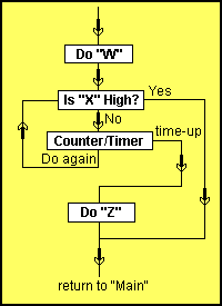
Flow diagram for "X", "Y" and "Z"
The counter/timer section "poles" or
"loops" an input line looking for a change. This is done many times
and forms a TIME DELAY. The counter/timer is loaded with a value and decrements
the count to zero. When the counter/timer is zero, the program executes the
"time-up" path.
|
Do "W"
AA
BB
Do "Z"
Delay
Del2
Del3
|
MOVLW 40h
MOVWF 1Ch
BSF 06h,0
CALL Delay
BCF 06,0
CALL Delay
BTFSS 06,1
GOTO BB
RETLW 00
DECFSZ 1Ch
GOTO AA
BSF 06,1
CALL Delay
BCF 06,1
RETLW 00
MOVLW 80h
MOVWF 1Ah
MOVLW 60h
MOVWF 1Bh
DECFSZ 1Bh
GOTO Del3
DECFSZ 1Ah
GOTO Del2
RETLW 00 |
;Load count-down file 1C
;Make RB0 HIGH
;Select Page0
;Make RB0 LOW
;Is input "X" HIGH?
;Yes. Return to Main
;Decrement count-down file
;Time not up. Do again
;Time up. Do "Z"
;Make
RB1 LOW
;Return to Main
;Load a value into file 1A
;Load a value into file 1B
;Return to the sub-routine above
|
| Program for
"X", "Y" , "Z"
statement above |
The time "Y" is made
up of the loops in the count-down file 1C and includes the length of time created by the
Delay.
The length of time taken by each of the operations "W" and
"Z" can be adjusted by the Delay sub-routine.
At the moment you don't know anything about the instructions we have used in
the program above or how to read
them but you can see approximately how may lines of code are required to
carry out the statement above.
The advantage of working in a low level language such as the instructions in
the program above, is the ability to tell the
microcontroller exactly what you want it to do, in the simplest, fastest
way. Producing a program in Machine Code or Mnemonic code is the closest you
can get to the type of instructions that are directly read by the
microcontroller and this is called a low-level language. A high level
language is an interpreter language such as BASIC or C++.
There are a number of "tricks" in the program above and these are
generally the placement of an instruction in an unusual place. One of
these is the placement of CALL Delay as the 6th instruction.
|
AA
|
CALL Delay
BTFSS 06,1
GOTO BB
RETLW 00
DECFSZ 1Ch |
;Is input "X" HIGH?
;Yes. Return to Main
;Decrement count-down file
|
This allows the Delay sub-routine to be called during each
loop of the counter/timer. Later in the course you will be shown the meaning of each
instruction and you will see why the only place for the CALL Delay
instruction is before decrementing the count file.
The other point you can observe at this early stage is the simplicity of the
instructions. Each letter stands for a word. For example, BTFSS 06,1
reads: Test Bit 1 of File 06 and Skip
if it is Set (1). The letters making up the instruction are called a Mnemonic and this simply means a "set of letters that are easy
to remember."
We cannot cover any more of the program until the instructions are fully
explained.
That's what we will do on the next set of pages:
Page 5: The
PIC12C508A Instruction-Set.
Page 6: The
PIC16F84 Instruction-Set.
Page 7: The
Instruction-Set Explained
NEXT
|