|
BURGLAR
ALARM |
|
|
The design for the
project comes from a number of requests for a low cost HOME ALARM.
Everything is done with a single 8-pin microcontroller and it reduces the chip-count and component-count to a minimum.
That's the advantage of a micro.
It can be programmed to monitor 4 inputs and produce a tone and wailing siren when an intrusion is detected. It also has all the "timing delays" and remembers which sector was detected.
This is the cheapest kit on the market and has some interesting features, never seen in an alarm.
The siren is activated when a door is opened or an item is touched and it starts very softly so that if it is a false alarm, you have time to reset the siren.
Most people hate turning on a house alarm as a false alarm is very frustrating and embarrassing. This design avoids that.
The second feature is the tamper switches.
Two of the inputs can be taken to items that are used as "bait" for the burglar. One of them can be money on a table. A small amount of money is left under a clip. When it is removed, the contacts touch each other and set-off the alarm.
The other "trap" is a drawer that is never used. When it is opened, it sets off the alarm.
Another feature is the 4 PIEZO SIRENS. This is an "add-on" future. The circuit contains one siren output. You can parallel 3 more driver circuits to get the 4 PIEZO SIRENS feature.
If you mount 4 x 80dB piezo sirens on the ceiling of a room, the sound is so deafening and disturbing that you cannot remain in the room. There is a phenomenon called "fringing" and the sound from each siren creates a "beat" of low frequency as well as the high-pitched sound. This is so annoying.
Because the burglar cannot hear if someone is approaching, he leaves immediately.
|
INSTRUCTIONS FOR USE The 4 inputs must be CLOSED via the 4 test switches provided in the kit. Turn the ALARM on. The two "ON" LEDs will illuminate as well as one of the INDICATOR LEDs. If the first indicator LED flashes once, the alarm will produce CONSTANT WAILING If the second indicator LED flashes 4 times, the alarm will wail for 5 minutes. To change the wailing, turn alarm OFF and push button A. Turn alarm ON and wait for indicator LED to flash either once or 4 times. Wait to hear the beeps and turn the alarm off. Turn alarm ON and the other indicator LED will flash. The exit piezo will now beep-beep-beep for 45 seconds to allow you to exit the premises. None of the sensors will activate the alarm during this time. After 45 seconds, open one of the switches and the Piezo Siren will beep-beep-beep for 10 seconds then wail for 5 minutes or constantly. The alarm is now ready for installation. |
PROGRAMMING THE
CHIP
BURGLAR ALARM
4-ZONE
Build the circuit on a piece of matrix
board (or the Circuit Board included in the kit) and connect the inputs
to the screw terminals. 6 separate 2-screw terminals are provided in the
kit to make it easy to wire-up the alarm. The alarm takes about 1mA when
monitoring a house and about 100mA when activated. POWER SUPPLY
This allows you to turn off the alarm
before the loud wailing is produced and is one of the best features of
the alarm as the worry of false-triggering an alarm prevents many
householders setting their alarm.
The main chip contains an internal
oscillator to drive a piezo diaphragm and also a wailing oscillator for
the Piezo Siren. The Piezo Siren is an 80dB piezo diaphragm driven by a
BD679 Darlington transistor with a 10mH choke to produce a high voltage
for the diaphragm.
Four switches are paced on the 4 inputs and pushed so the contacts
are CLOSED.
Here are the files you will need:
Burglar
Alarm
5/1/2014
The CIRCUIT
The circuit is very simple. All
the work is done by the micro.
The micro is designed to work on 5v and the supply to it must not be more than
5.6v.
The alarm is supplied from a 12v battery and a very clever
voltage-dropping arrangement has been provided to delver a maximum of
5v6 to the micro.
This is the section of the circuit that will be taking current when the
project is turned ON. That's why we have taken special care to keep the
current very low, so the circuit can operate on a rechargeable battery
or even two lantern batteries.
The supply contains two high-brightness LEDs to drop the 12v supply by
1.7v for each LED. This delivers 12.6v - 1.7v - 1.7v = 9.2v to the right
end of the 1k5 resistor. The left side is a maximum of 5v6 and the
difference is 3.6v. This produces a current of 2.4mA.
This current is available for the micro.
When the micro is in the "detection mode" is takes less than 1mA and the
remainder of the current flows though the 5v6 zener.
When one of the indicator LEDs is flashing, or button A is pressed, or
the piezo buzzer is sounding, or the piezo siren is active, the 5v
section takes more than 1mA and can take up to 2.4mA. At this point the circuit
takes all the current that is available via the 1k5 resistor and the voltage drops to 5.5v.
This takes the zener out of conduction and the micro consumes all the
current.
The flashing LEDs will take more than 2.4mA for a short
period of time and the 100u electrolytic will deliver this extra current
and charge during the "off time."
This arrangement takes the least current from the battery as a 78L05
requires 10mA and you would need to use a special low-current regulator
to achieve what we have done.
The circuit has been designed around easy-to-obtain components.
There are two clever features that need describing.
The 4 inputs are monitored by turning on the 47k pull-up resistors
inside the micro and this creates a voltage-divider between the external
resistors and the internal 47k's.
The 1k resistor across the LEDs keeps the "bottom resistor" in the
divider very low and prevents 1.7v developing across the LEDs as this
would be detected as a HIGH (the chip detects anything above about 1v5 as
a HIGH).
The 22n across switch A is charged by the program for a very short
period of time then the pin is turned into an input to see if the
capacitor is still charged. SwA will discharge the 22n very quickly if
it is pushed.
This is the only way to detect if SwA is pressed. The internal 47k's
cannot pull the input high enough to record a HIGH when the 10k is used
as a base resistor.
The siren piezo has a transistor driver to produce maximum output and
the
buzzer piezo has a transistor driver and 10mH choke to increase the
output. This allows you to use low-cost piezo diaphragms for both.
CONSTRUCTION
You can build the circuit on
matrix board or use the ALARM 4-ZONE Printed Circuit board included in
the kit.
The kit of components comes with all the parts you need to get the
project working, including a pre-programmed chip.
If you want to burn your own chip or modify the program, you will need a PICkit-2 programmer and this comes
with 2 CD's containing all the software needed for In-Circuit
Programming.
You will also need a lead (comes with PICkit-2) to connect the programmer to your lap top via
the USB port and an adapter we call 6pin to 5 pin
Adapter to connect
the PICkit-2 to your project.
FITTING THE ALARM
The board comes with screw terminals for the 4 inputs and a set of
terminals for the 12v supply as well as the leads to the piezo siren.
This makes it easy to install.
Simply build the circuit and mount it inside a cupboard where it will
not be seen.
2 x 6v lantern batteries will last 3,000 hours (125 days) or a 12v gel
cell will last 6 months. But the alarm is only active for a few hours
each day and the battery-life will not be a problem.
Mount the siren piezo some distance from the alarm in a high location.
It will be so loud that the burglar will leave the premises.
You can add a second siren piezo and mount it outside.
Any unused inputs need to have a "shorting link" added across the
terminals of the unused input.
Cover the hole in the piezo to reduce the sound when initially testing
the project.
The alarm will wail constantly if you have chosen the first flashing LED
via the mini tactile switch "A." or it will only sound for 5 minutes if
the middle LED is flashing.
The kit comes with a pre-programmed PIC chip but if you want to program
your own chip or modify the program, the .hex file is available as well
as the assembly file, so you can see how the program has been written
and view the comments for each line of code.
The PIC12F629 is one of the smallest micros in the range but you will be
surprised how much can be achieved with such a tiny micro.
The program contains sub-routines to produce delays, sequences on the
display and both read and write EEPROM; jobs that require accurate code
- including a special sequence - called a handshaking sequence that
prevents the EEPROM being written due to glitches.
Even a program as simple as this is not easy to put together and to
assist in this area, we have provided a whole raft of support material.
Not only do we provide a number of programs with full documentation but
our approach to programming is simple.
It involves a method of "copy and paste" whereby sub-routines
are taken from previously written code and copied into your program. Any modifications are
made in very small steps so that each can be tested before adding more
code.
This is exactly how we produce a complex project. Each step is written
and tested before adding the next step.
This saves a lot of frustration as it is very easy to add a line
of code that is incorrect and get an unsuspected result.
If you follow our suggestions you will buy a programmer ("burner")
called a PICkit-2 if you are using a laptop. It is the cheapest and best on the market
and comes with
a USB
cable and 2 CD's containing the programs needed to "burn" the chip.
If you are using a desk-top and/or tower with a serial port, you can use
a cheaper programmer called MultiChip Programmer from Talking
Electronics. You
will also need NotePad2 to write your .asm program. This can be
downloaded from Talking Electronics website. You will use
Alarm4Zone.asmm or
Alarm4Zone-asm.txt as a
basis and it is best to change only a few lines at a time to see what
effect is created. You will also need a 6 pin to 5 pin connector that fits between the burner
and the project. This is also available on Talking Electronics website.
As we said before, this project is for medium-to-advanced programmers as
it is very compact and does not have in-circuit programming pins.
To be able to modify the chip you will need a programming socket and
this can be obtained from one of our other projects that contains the 5
pins for in-circuit programming. Or you can build a programming socket
by adding a socket to a surface-mount PC board and solder 5 pins to one
edge and connect the socket to the pins.
You can then put the chip into the socket and program it.
PROGRAMMING LANGUAGE
There are a number of kits, programs and
courses on the market that claim and suggest they teach PIC Programming.
Most of these modules and courses use a PIC microcontroller as the chip carrying out
the processes, but the actual programming is done by a proprietary
language invented by the designer of the course.
Although these courses are wonderful to get you into "Programming
Microcontrollers" they do not use any of the terms or codes that apply
to the PIC microcontroller family.
All our projects use the 33 instructions that come with the PIC
Microcontroller and these are very easy to learn.
We use the full capability of the micro and our pre-programmed chip is
less than the cost of doing it any other way.
In addition, anything designed via our method can be instantly
transferred to a PIC die and mass produced. And we use all the input
pins and all the memory of the chip. The other approaches
use less than 25% of the capability of the memory and one of the pins is not available.
In fact it would be difficult to reproduce this project via any of the opposition
methods. It would require a larger chip and more expense.
You can use our method or the opposition. Just be aware that the two are
not interchangeable.
Ours is classified as the lowest "form" (level) of programming - commonly called
machine code - invented in the early days of microprocessors - and now
called mnemonic programming as each line of code is made up of
letters of a set of words. The opposition uses a higher level language
where one instruction can carry out an operation similar to a
sub-routine.
But you have to learn the "higher level language" in order to create a
program. And this requires a fair amount of skill and capability.
It sounds great and it is a good idea. But if you want to learn PIC
programming, it does not assist you. It is "a step removed" from
learning PIC language. The other disadvantage of the opposition is the
"overhead." The 1,000 spaces allocated for your program is filled with
pre-written sub-routines. You may require only 10 of these sub-routines but ALL
of them are loaded in the memory space. And they take up all the memory.
You have no room for your own program.
To get around this the opposition uses the 128 bytes in EEPROM to deliver
instructions on how to apply the sub-routines. This provides about 30 powerful instructions using their
language called BASIC (or a similar language).
It's a bit like selling a diary filled with all the paragraphs you need
to express yourself, and leaving a few blank pages at the back for you
to write single lines such as: see page 24, paragraph 7, see page 63
paragraph 4, to create your diary entries.
It depends on how much you want to be in charge of writing a program. Using
our method is like writing your own auto-biography. Using the opposition
is like getting a "ghost writer."
When using a higher level language to create a program, you have absolutely no
idea how the code is generated for the micro.
In some of the developmental kits, the code is "locked away" and you are
NEVER able to access it.
Everything runs smoothly until a fault appears. With our method you can
see the code. With the other methods, you cannot see the code - it's
like doing key-hole surgery without the advantage of an
illuminated endoscope to see what you are doing.
Everything has its place and our method of hand-assembly is only
suitable for very small micros and you will eventually need to "learn a
high level language." The PIC12F629 has over 1,000 locations for code
and this equates to more than 20 pages when printed, so this is about
the limit to doing things by hand.
But our drive is to show how much can be done with the simplest devices
on the market, at the lowest cost.
Anyone can show you high-technology at a high price but this is not
where you start and this is not where you get enthusiasm.
We provide the things to get you started. That's the difference.
This circuit uses a dedicated alarm chip from Talking Electronics (TE555-BA4).
The chip costs $2.50 and contains a 4-zone Burglar Alarm circuit. All
you need are the surrounding components to complete the project. These
components are available as a kit for $20.00 including the dedicated
chip and this makes it one of the cheapest kits on the market (postage
for kit $6.50). Click
HERE
to order the chip or the kit.
The only additional parts you require are 4 reed switches. These can be
purchased on eBay for $5.38 for a set of 5 Normally Open switches (post
free).
Here is the link:
http://www.ebay.com/itm/5-Set-Door-Or-Window-Safety-Contact-Magnetic-Alarm-Reed-Switch-NO-with-Screws-/290746194636?pt=LH_DefaultDomain_0&hash=item43b1d2dacc

The siren is only activated ONCE for 5 minutes when a break-in occurs as
this is the maximum allowable time for a siren to wail in Australia.
If you want the alarm to constantly wail after a break-in, push button A
when the alarm is turned on (and the exit beep is being produced). The
constantly wailing LED will flash. Push the button again and the 5
minute LED will flash. The button toggles between the two features.
You can use reed switches for the input devices for doors and drawers.
You can also trap the burglar by placing money under a clip and have a
very thin length of tinned copper wire wound around two pins. When the
money is removed, the wire is pulled off the pins. A single strand of
wire can be obtained from a length of hook-up flex.
The alarm can be connected to a 12v gell cell with a rating of 1.2AHr
and it can be automatically charged using our
Automatic Battery Charger in 101 Transistor Circuits.
http://www.talkingelectronics.com/projects/200TrCcts/101-200TrCcts.html#84
HOW THE CIRCUIT WORKS
Any of the inputs can be used for the Entry/Exit.
It is connected to the door you will use to enter or exit the property.
The alarm gives you 45 seconds to exit.
When you enter the property, the buzzer turns on as soon as you open the
door and beeps for 45 seconds to allow you to turn off the alarm.
If the alarm is not turned off, the main piezo siren produces a soft
tone for 30 seconds and then a piercing wailing sound. 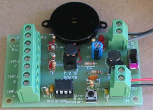
Any unused inputs must be connected with a link so the alarm can be set.
When the circuit is turned ON, you have 45 seconds to exit the premises.
The chip then flashes either the 5-min LED or the Constant LED to
indicate if the siren will wail for 5 minutes or constantly. You can
change the setting by pressing the button. The circuit then beeps for 45
seconds to give you time to exit the property. It then monitors all 4
inputs.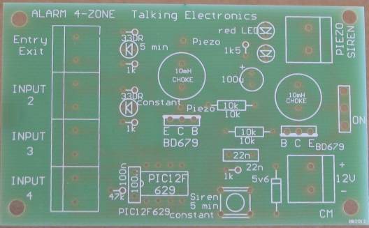
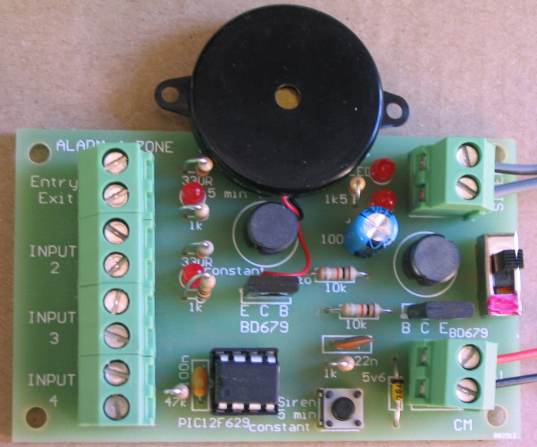
Alarm 4-Zone PCB
The chip operates on 5v and the rest of the circuit uses 12v. A very
simple voltage-dropper consisting of 2 LEDs and 1k5 drops the 12v to
5v.
TESTING 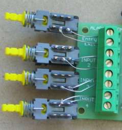
The project can now be tested by going through the INSTRUCTIONS FOR USE
(above).
Alarm4Zone.asm
Alarm4Zone-asm.txt
Alarm4Zone.hex
;*************************************************************
;;Alarm 4-Zone.asm
;*************************************************************
; Alarm4Zone.asm	for PIC12F629   16-12-2013
;;	Alarm4Zone.asm	for PIC12F629   6-1-2014
;
;

	radix	dec
	include	"p12f629.inc"

	errorlevel -302	; Don't complain about BANK 1
          ;Registers during assembly

	__CONFIG	_MCLRE_OFF & _CP_OFF & _WDT_OFF &
           _INTRC_OSC_NOCLKOUT  ;Internal osc.


STATUS	equ	3
PC	equ	2
#define	CARRY	STATUS,0
#define	ZERO	STATUS,2


	;Files:

flags	equ	20h	 ;flags file
tempA	equ	21h
delA	equ	22h
delB	equ	23h
delC	equ	24h
dwell   equ     25h
steps   equ     26h
count   equ     27h
temp1	equ	28h
loops	equ     29h
store	equ     2Ah  ;stores triggered input No
loop30  equ     2Bh  ;loops for 5 minute siren

	org	0
	goto	SetUp
	nop


SetUp
	movlw   07h           ;Set up W to turn off Comparator ports
	movwf   CMCON         ;must be placed in bank 0
	goto	Main


;**************************
;* Delays 			*
;**************************


_1mS	movlw   .40      ;reduced to 40/255 of 1mS
        movwf   delA
	decfsz 	delA,f
	goto 	$-1
	retlw 	00


	;240mS delay


_240mS	nop
	decfsz 	delA,1
	goto 	$-2
	decfsz 	delB,1
	goto 	$-4
	retlw 	00


_500mS	goto	$+1
	goto	$+1
	decfsz 	delA,1
	goto 	$-3
	decfsz 	delB,1
	goto 	$-5
	retlw 	00


;****************************
;* Sub-routines		*
;****************************

	;beep-beep-beep to siren for soft start

beep
	movlw	.50
	movwf	tempA
	bsf	gpio,5
	movlw	.40
	movwf	delA
	nop
	decfsz	delA,f
	goto	$-2
	bcf	gpio,5
	movlw	.240
	movwf	delA
	goto	$+1
	decfsz	delA,f
	goto	$-2
	decfsz	tempA,f
	goto	$-13
	call	_240mS
	retlw	00

	;Charge 22n

Charge	bsf	status,rp0 	  ;Bank 1
	movlw	b'00101111'
	movwf   trisio		;Make GP0,1,2,3,5 input   GP4 output
	bcf	status,rp0	  ;bank 0
	bsf	gpio,4
	call	_1mS          ;charge 22n
	bsf		status,rp0 	  ;Bank 1
	movlw	b'00111111'
	movwf   trisio		;Make GP0,1,2,3,5 input   GP4 input
	bcf	status,rp0	  ;bank 0
	bcf	gpio,4
	call	_1mS          ;time for swA to discharge 22n
	retlw   00


	;Indicate
    ;flash 1 time for constant wailing or 4 times for 5 minutes wailing

Indicate

	bsf	status,rp0 	  ;Bank 1
	movlw	b'00111001'
	movwf   trisio		  ;Make GP1,2 output
	bcf	status,rp0	  ;bank 0
	clrf    gpio		 ;make outputs low to turn off LEDs,
	call 	read 		  ;read 0 or 1 from EEPROM location 1
	btfss   temp1,0
	goto    Ind_1
	bsf	gpio,2       ;temp1 = 1   = contant siren
	call	_500mS
	bcf	gpio,2
	call	_500mS
	retlw	00

Ind_1	bsf	gpio,1       ;temp1 = 0 = 5 minute siren
	call	_500mS
	bcf	gpio,1
	call	_500mS
	bsf	gpio,1
	call	_500mS
	bcf	gpio,1
	call	_500mS
	bsf	gpio,1
	call	_500mS
	bcf	gpio,1
	call	_500mS
	bsf	gpio,1
	call	_500mS
	bcf	gpio,1
	call	_500mS
	retlw	00


   ;read takes the value 0 or 1 from EEPROM location 0 and puts in temp1

read
	movlw	.0
	bsf	status,rp0
	movwf	EEADR
	bsf	EECON1,0  ;starts EEPROM read operation result in EEDATA
	movf	EEDATA,w	;move read data into w
	bcf	status,rp0
	movwf	temp1	;temp1 has the value 0 or 1 to flash a LED
	retlw	00


	;SIREN - WAILING SIREN

Siren	movlw	7	;number of steps
	movwf	steps

Siren1	movlw	5	;dwell
	movwf	dwell
	bsf     gpio,5
	movf	count,0
	movwf	tempA
	decfsz	tempA,1
	goto	$-1
	bcf     gpio,5
	movf	count,0
	movwf	tempA
	goto	$+1
	goto	$+1
	goto	$+1
	decfsz	tempA,1
	goto	$-4
	decfsz	dwell,1		;
	goto	$-14
	movlw	5
	subwf	count,1	   	;
	decfsz	steps,1	    ;
	goto	Siren1
	retlw   00


	;Siren Beeps for 10 seconds

SirenBeep
	bsf	status,rp0 	  ;Bank 1
	movlw	b'00011111'
	movwf   trisio		  ;Make GP0,1,2,3,4 input   GP5 output
	bcf	status,rp0	  ;bank 0
	movlw	.50           ;number of loops (cycles)
	movwf	tempA
SirenBeep1
	bsf	gpio,5        ;siren BD679 HIGH
	movlw	.40
	movwf	delA
	nop
	decfsz	delA,f
	goto	$-2
	bcf	gpio,5        ;siren BD679 LOW for: 255 delA
	nop
	decfsz	delA,f
	goto	$-2
	decfsz	tempA,f
	goto	SirenBeep1
	call	_240mS		 ;silence
	retlw	00


	;exit tone to piezo buzzer
tone		;524Hz for 250mS
	bsf	status,rp0 	  ;Bank 1
	movlw	b'00101111'
	movwf   trisio		  ;Make GP0,1,2,3,5 input   GP4 output
	bcf	status,rp0	  ;bank 0
	movlw	.50           ;number of loops (cycles)
	movwf	tempA
tone1	bsf	gpio,4        ;buzzer BD679 HIGH
	movlw	.40
	movwf	delA
	nop
	decfsz	delA,f
	goto	$-2
	bcf	gpio,4        ;buzzer BD679 LOW for: 255 delA
	nop
	decfsz	delA,f
	goto	$-2
	decfsz	tempA,f
	goto	tone1
	call	_240mS		 ;silence
	retlw	00


write
	bsf	status,rp0	;select bank1
	movwf	EEDATA
	bcf	status,rp0	;select bank0
	movlw	.0
	bsf	status,rp0	;select bank1
	movwf	EEADR
	bsf	eecon1,wren	;enable write
	movlw	55h 		;unlock codes
	movwf	eecon2
	movlw	0aah
	movwf	eecon2
	bsf	eecon1,wr	;write begins
	bcf	status,rp0	;select bank0
writeA	btfss	pir1,eeif	;wait for write to complete
	goto	writeA
	bcf	pir1,eeif
	bsf	status,rp0	;select bank1
	bcf	eecon1,wren	;disable other writes
	bcf	status,rp0	;select bank0
	retlw	00


;****************************
;* Main
;****************************


Main	;45 second exit with button A detect
		;exit beep produced

	clrf	store	;stores triggered input No
	movlw   .180       ; 180 x 250mS = 45 seconds
	movwf   loops
	call	Indicate   ;flash LED 4 times


M1	call    Charge
	btfsc	gpio,4		;is button A pressed?
	goto	M2          ;not pressed
	call 	read		;0 or 1 will be in temp1
	btfss	temp1,0
	goto	$+4
	clrf	w
	call	write
	goto    M2
	movlw	1
	call	write

M2	call	tone    ;call exit tone
        decfsz	loops,1
	goto	$-2


	;monitors 4 inputs

Monitor	bsf	status,rp0	;select bank1
	movlw	b'00101111'
	movwf   trisio		  ;Make GP0,1,2,3,5 input   GP4 output
	bcf     81h,7         ;turn on pulls-ups in option_reg
	movlw	b'00000111'
	movwf   095h          ;WPU register for GP0,1,2
	bcf	status,rp0	  ;bank 0
	btfsc   gpio,0
	goto	Mon1
	btfsc   gpio,1
	goto	Mon1
	btfsc   gpio,2
	goto	Mon1
	btfsc   gpio,3
	goto	Mon1
	goto    Monitor

Mon1	bsf	status,rp0	;select bank1
	bcf     trisio,5	;Make GP5 output
	bcf	status,rp0	  ;bank 0


		;soft-start siren with beeps for 10 seconds


	movlw  .40
	movwf  loops
	call   SirenBeep
        decfsz	loops,1
	goto	$-2

	;constant siren if temp1,0 = 1
	;5 minute siren if temp1,0 = 0

	btfss   temp1,0
	goto    Siren5min
	call	Siren      ;constant siren
	goto    $-1


Siren5min

       	movlw   .30      ;30 loops
       	movwf   loop30
       	movlw  .185      ;inner loop = 10 seconds
	movwf  loops
	call   Siren
        decfsz	loops,1
	goto	$-2
	decfsz	loop30,1
	goto	$-6
	goto    $


;************************************
;*EEPROM     						*
;************************************

	org		2100h

	de		00h

	END
4-Zone
Parts List
Cost:
au$20.00
plus postage
Kits
are available
3 - 1k
resistors
2 - 330R
1 - 1k5
resistor
2 - 10k resistor
1 - 47k resistor
1 - 22n
1 - 100n capacitor
1 - 100u electrolytics
2 - BD679 transistors
1 - 5v6 400mW zener diode
4 - 3mm super-bright red LEDs
1 - SPDT mini slide switch
1 - mini tactile switch
1 - 8 pin IC socket
1 - PIC12F629 chip (Alarm routine)
1 - mini piezo diaphragm
1 - 80dB piezo transducer
2 - 10mH chokes
6 - 2-screw terminals or 2x3
and 3x2-screw
1m fine screened lead for piezo
20cm very fine solder
1 - Alarm 4-zone PC board
4 -
Switches to test the
project