

 The output voltage depends on how quickly the magnet passes from one
end of the slide to the other. That's why a rapid shaking produces a
higher voltage. You must get the end of the magnet to fully pass
though the coil so the voltage will be a maximum. That’s why the
slide extends past the coils at the top and bottom of the diagram.
The output voltage depends on how quickly the magnet passes from one
end of the slide to the other. That's why a rapid shaking produces a
higher voltage. You must get the end of the magnet to fully pass
though the coil so the voltage will be a maximum. That’s why the
slide extends past the coils at the top and bottom of the diagram.


.gif)
 This
project is available as a kit for $10.80 plus $6.50 post. email
This
project is available as a kit for $10.80 plus $6.50 post. email
 This
circuit will operate a two-solenoid point-motor and prevent it
overheating and causing any damage. The circuit produces energy to
change the points and ceases to provide any more current. This
is carried out by the switching arrangement within the circuit, by
sampling the output voltage.
This
circuit will operate a two-solenoid point-motor and prevent it
overheating and causing any damage. The circuit produces energy to
change the points and ceases to provide any more current. This
is carried out by the switching arrangement within the circuit, by
sampling the output voltage. 
 This
circuit is multiplied 4 times on the module to control 4 Kato
points.
This
circuit is multiplied 4 times on the module to control 4 Kato
points.
 When
the voltage rises more than 0.6v above rail voltage, the dynamo
needs to deliver current and this will allow the rail voltage to
increase. We start with the dynamo producing negative from the left
side and positive on the right side.
When
the voltage rises more than 0.6v above rail voltage, the dynamo
needs to deliver current and this will allow the rail voltage to
increase. We start with the dynamo producing negative from the left
side and positive on the right side. 
 RL must be low enough to guarantee
at least a 30mA. It can be a
separate resistor or part of the actual load.
RL must be low enough to guarantee
at least a 30mA. It can be a
separate resistor or part of the actual load.


save as: 101-200 Transistor circuits.pdf (1-6-2019)
save as:
101-200 Transistor circuits.pdf
(1-6-2019)
Go to: 1 -
100 Transistor Circuits
Go to: 100
IC Circuits

See TALKING ELECTRONICS WEBSITE
email Colin Mitchell:
talking@tpg.com.au
| INTRODUCTION This is the second half of our Transistor Circuits e-book. It contains a further 100 circuits, with many of them containing one or more Integrated Circuits (ICs). It's amazing what you can do with transistors but when Integrated Circuits came along, the whole field of electronics exploded. IC's can handle both analogue as well as digital signals but before their arrival, nearly all circuits were analogue or very simple "digital" switching circuits. Let's explain what we mean. The word analogue is a waveform or signal that is changing (increasing and decreasing) at a constant or non constant rate. Examples are voice, music, tones, sounds and frequencies. Equipment such as radios, TV's and amplifiers process analogue signals. Then digital came along. Digital is similar to a switch turning something on and off. The advantage of digital is two-fold. Firstly it is a very reliable and accurate way to send a signal. The signal is either HIGH or LOW (ON or OFF). It cannot be half-on or one quarter off. And secondly, a circuit that is ON, consumes the least amount of energy in the controlling device. In other words, a transistor that is fully turned ON and driving a motor, dissipates the least amount of heat. If it is slightly turned ON or nearly fully turned ON, it gets very hot. And obviously a transistor that is not turned on at all will consume no energy. A transistor that turns ON fully and OFF fully is called a SWITCH. When two transistors are cross-coupled in the form of a flip flop, any pulses entering the circuit cause it to flip and flop and the output goes HIGH on every second pulse. This means the circuit halves the input pulses and is the basis of counting or dividing. Digital circuits also introduce the concept of two inputs creating a HIGH output when both are HIGH and variations of this. This is called "logic" and introduces terms such as "Boolean algebra" and "gates." Integrated Circuits started with a few transistors in each "chip" and increased to whole mini or micro computers in a single chip. These chips are called Microcontrollers and a single chip with a few surrounding components can be programmed to play games, monitor heart-rate and do all sorts of amazing things. Because they can process information at high speed, the end result can appear to have intelligence and this is where we are heading: AI (Artificial Intelligence). But let's crawl before we walk and come to understand how to interface some of these chips to external components. In this Transistor Circuits ebook, we have presented about 100 interesting circuits using transistors and chips. In most cases the IC will contain 10 - 100 transistors, cost less than the individual components and take up much less board-space. They also save a lot of circuit designing and quite often consume less current than discrete components. In all, they are a fantastic way to get something working with the least componentry. A list of of Integrated Circuits (Chips) is provided at the end of this book to help you identify the pins and show you what is inside the chip. Some of the circuits are available from Talking Electronics as a kit, but others will have to be purchased as individual components from your local electronics store. Electronics is such an enormous field that we cannot provide kits for everything. But if you have a query about one of the circuits, you can contact me. Colin Mitchell TALKING ELECTRONICS. talking@tpg.com.au
To save space we have not provided lengthy explanations of how the
circuits work. This has already been covered in TALKING ELECTRONICS
Basic Electronics Course, and can be obtained on a
CD for $10.00
(posted
to anywhere in the world) See Talking Electronics website for more
details:
http://www.talkingelectronics.com
MORE INTRO |
|
RESISTOR COLOUR CODE
|
|
RECTIFYING a Voltage These circuits show how to change an oscillating voltage (commonly called AC) to DC. The term AC means Alternating Current but it really means Alternating Voltage as the rising and falling voltage produces an increasing and decreasing current. The term DC means Direct Current but it actually means Direct or unchanging Voltage. The output of the following circuits will not be pure DC (like that from a battery) but will contain ripple. Ripple is reduced by adding a capacitor (electrolytic) to the output.   |
 DARK DETECTOR with beep-beep-beep Alarm This circuit detects darkness and produces a beep-beep-beep alarm. The first two transistors form a high-gain amplifier with feedback via the 4u7 to produce a low-frequency oscillator. This provides voltage for the second oscillator (across the 1k resistor) to drive a speaker. |
Project can turn ON when
DARK This circuit detects darkness and allows the project to turn on. The project can be any circuit that operates from 3v to 12v. The components have been chosen for a 6v project that requires 500mA. |
 3-PHASE SINEWAVE GENERATOR This circuit produces a sinewave and each phase can be tapped at the point shown. The secret to producing a good waveform is the addition of the 2k2 resistor in the 0v rail This circuit and waveform is provided by Jack Hoffnung. 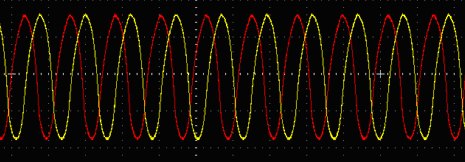 Two of the three waveforms - we only have dual trace CRO's !!!! |
|
This clever design uses 4 diodes in a bridge to produce a fixed voltage power supply capable of supplying 35mA. All diodes (every type of diode) are zener diodes. They all break down at a particular voltage. The fact is, a power diode breaks down at 100v or 400v and its zener characteristic is not useful. But if we put 2 zener diodes in a bridge with two ordinary power diodes, the bridge will break-down at the voltage of the zener. This is what we have done. If we use 18v zeners, the output will be 17v4. When the incoming voltage is positive at the top, the left zener provides 18v limit (and the other zener produces a drop of 0.6v) This allows the right zener to pass current just like a normal diode. The output is 17v4. The same with the other half-cycle. The current is limited by the value of the X2 capacitors and this is 7mA for each 100n when in full-wave (as per this circuit). We have 1u capacitance. Theoretically the circuit will supply 70mA but we found it will only deliver 35mA before the output drops. The capacitors should comply with X1 or X2 class. The 10R is a safety-fuse resistor. The problem with this power supply is the "live" nature of the negative rail. When the power supply is connected as shown, the negative rail is 0.7v above neutral. If the mains is reversed, the negative rail is 340v (peak) above neutral and this will kill you as the current will flow through the diode and be lethal. You need to touch the negative rail (or the positive rail) and any earthed device such as a toaster to get killed. The only solution is the project being powered must be totally enclosed in a box with no outputs. A TRANSFORMERLESS POWER SUPPLY is also called a CAPACITOR FED POWER SUPPLY. It is very dangerous. Here's why: A Capacitor Power Supply uses a capacitor to interface between a “high voltage supply” and a low voltage – called THE POWER SUPPLY. In other words a capacitor is placed between a “high voltage supply” we call THE MAINS (between 110v and 240v) and a low voltage that may be 9v to 12v. Even though a capacitor consists of two plates that do not touch each other, a Capacitor Power Supply is a very dangerous project, for two reasons. You may not think electricity can pass though a capacitor because it consists of plates that do not touch each other. But a capacitor works in a slightly different way. A capacitor connected to the mains works like this: Consider a magnet on one side of a door. On the other side we have a sheet of metal. As you slide the magnet up the door, the sheet of metal rises too. The same with a capacitor. As the voltage on one side of the capacitor rises, the voltage on the other side is “pulled out of the ground” - and it rises too. If you stand on the ground and hold one lead of the capacitor and connect the other to the active side of the “mains,” the capacitor will “pull” 120v or 240v “out of the ground” and you will get a shock. Don’t ask “how” or “why.” This is just the simplest way to describe how you get a shock via a capacitor that consists of two plates. If the capacitor “shorts” between the two plates, the 120v or 240v will be delivered to your power supply and create damage. Secondly, if any of the components in your power supply become open-circuit, the voltage on the power supply will increase. But the most dangerous feature of this type of power supply is reversal of the mains leads. The circuit is designed so that the neutral lead goes to the earth of your power supply. This means the active is connected to the capacitor. Now, the way the active works is this: The active lead rises 120x 1.4 = 180v in the positive direction and then drops to 180v in the opposite direction. In other words it is 180v higher than the neutral line then 180v lower than the neutral. For 240v mains, this is 325v higher then 325v lower. The neutral is connected to the chassis of your project and if you touch it, nothing will happen. It does not rise or fall. But suppose you connect the power leads around the wrong way. The active is now connected to the chassis and if you touch the chassis and a water pipe, you will get a 180v or 345v shock. That’s why a CAPACITOR-FED power supply must be totally isolated. Now we come to the question: How does a capacitor produce a 12v power supply? When a capacitor is connected to the mains, one lead is rising and falling. Depending on the size of the capacitor, it will allow current to flow into and out of the other lead. If the capacitor is a large value, a high current will flow into and out of the lead. In addition, a high voltage will allow a higher current to flow. This current is “taken out of the ground” and “flows back into the ground.” It does not come from the mains. The mains only: “influences” the flow of current. Thus we have a flow of current into and out of the capacitor. If you put a resistor between the capacitor and “ground,” the amount of current that will flow, depends on 3 things, the amplitude of the voltage, the size of the capacitor and the speed of the rise and fall. When current flows through a resistor, a voltage develops across the resistor and if we select the correct value of resistance, we will get a 12v power supply. THE OUTPUT VOLTAGE The OUTPUT VOLTAGE of all transformerless power supplies will be about 50% HIGHER than the mains voltage if a LOAD is not connected. That's RIGHT: The output of a 120v CAPACITOR POWER SUPPLY (transformerless power supply) will be about 180v and a 240v mains transformerless power supply will be about 345v. How do you get a 12v or 24v supply???? It works like this: The transformerless power supply is a CURRENT-DELIVERED power supply. In other words we have to talk about CURRENT-VALUES and not voltages. For a bridge circuit (called a full-wave design) it will deliver 7mA for each 100n. Suppose we have 220n. We have 15mA available. We take the 15mA and say: How many volts will develop across a 100R load? The answer = 0.015 x 100 = 15v. I f we use 82R the voltage will be about 12v. If we use 220R the voltage will be 33v. That's how the output voltage is developed. If you add another 220n across the 220n, the voltages will be DOUBLE. It's as simple as that. |
 LEDs
on 240v LEDs
on 240vI do not like any circuit connected directly to 240v mains. However Christmas tress lights have been connected directly to the mains for 30 years without any major problems. Insulation must be provided and the lights (LEDs) must be away from prying fingers. You need at least 50 LEDs in each string to prevent them being damaged via a surge through the 1k resistor - if the circuit is turned on at the peak of the waveform. As you add more LEDs to each string, the current will drop a very small amount until eventually, when you have 90 LEDs in each string, the current will be zero. For 50 LEDs in each string, the total characteristic voltage will be 180v so that the peak voltage will be 330v - 180v = 150v. Each LED will see less than 7mA peak during the half-cycle they are illuminated. The 1k resistor will drop 7v - since the RMS current is 7mA (7mA x 1,000 ohms = 7v). No rectifier diodes are needed. The LEDs are the "rectifiers." Very clever. You must have LEDs in both directions to charge and discharge the capacitor. The resistor is provided to take a heavy surge current through one of the strings of LEDs if the circuit is switched on when the mains is at a peak. This can be as high as 330mA if only 1 LED is used, so the value of this resistor must be adjusted if a small number of LEDs are used. The LEDs above detect peak current. A 100n cap will deliver 7mA RMS or 10mA peak in full wave or 3.5mA RMS (10mA peak for half a cycle) in half-wave. (when only 1 LED is in each string).  The
current-capability of a capacitor needs more explanation. In the
diagram on the left we see a capacitor feeding a full-wave power supply.
This is exactly the same as the LEDs on 240v circuit above.
Imagine the LOAD resistor is removed. Two of the diodes will face down
and two will face up. This is exactly the same as the LEDs facing up and
facing down in the circuit above. The only difference is the mid-point
is joined. Since the voltage on the mid-point of one string is the same
as the voltage at the mid-point of the other string, the link can be
removed and the circuit will operate the same. The
current-capability of a capacitor needs more explanation. In the
diagram on the left we see a capacitor feeding a full-wave power supply.
This is exactly the same as the LEDs on 240v circuit above.
Imagine the LOAD resistor is removed. Two of the diodes will face down
and two will face up. This is exactly the same as the LEDs facing up and
facing down in the circuit above. The only difference is the mid-point
is joined. Since the voltage on the mid-point of one string is the same
as the voltage at the mid-point of the other string, the link can be
removed and the circuit will operate the same. This means each 100n of capacitance will deliver 7mA RMS (10mA peak on each half-cycle). In the half-wave supply, the capacitor delivers 3.5mA RMS (10mA peak on each half-cycle, but one half-cycle is lost in the diode) for each 100n to the load, and during the other half-cycle the 10mA peak is lost in the diode that discharges the capacitor. You can use any LEDs and try to keep the total voltage-drop in each string equal. Each string is actually working on DC. It's not constant DC but varying DC. In fact is it zero current for 1/2 cycle then nothing until the voltage rises above the total characteristic voltage of all the LEDs, then a gradual increase in current over the remainder of the cycle, then a gradual decrease to zero over the falling portion of the cycle, then nothing for 1/2 cycle. Because the LEDs turn on and off, you may observe some flickering and that's why the two strings should be placed together. |
 BOOK
LIGHT BOOK
LIGHTThis circuit keeps the globe illuminated for a few seconds after the switch is pressed. There is one minor fault in the circuit. The 10k should be increased to 100k to increase the "ON" time. The photo shows the circuit built with surface-mount components: 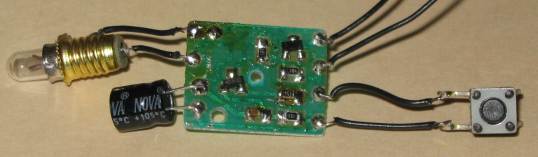 |
 CAMERA ACTIVATOR This circuit was designed for a customer who wanted to trigger a camera after a short delay. The output goes HIGH about 2 seconds after the switch is pressed. The LED turns on for about 0.25 seconds. The circuit will accept either active HIGH or LOW input and the switch can remain pressed and it will not upset the operation of the circuit. The timing can be changed by adjusting the 1M trim pot and/or altering the value of the 470k. |
POWER SUPPLIES - FIXED: A simple power supply can be made with a component called a "3-pin regulator or 3-terminal regulator" It will provide a very low ripple output (about 4mV to 10mV provided electrolytics are on the input and output. The diagram above shows how to connect a regulator to create a power supply. The 7805 regulators can handle 100mA, 500mA and 1 amp, and produce an output of 5v, as shown. These regulators are called linear regulators and drop about 4v across them - minimum. If the current flow is 1 amp, 4watts of heat must be dissipated via a large heatsink. If the output is 5v and input 12v, 7volts will be dropped across the regulator and 7watts must be dissipated. |
POWER SUPPLIES - ADJUSTABLE: The LM317 regulators are adjustable and produce an output from 1.25 to about 35v. The LM317T regulator will deliver up to 1.5amp. |
POWER SUPPLIES - ADJUSTABLE using 7805: The 7805 range of regulators are called "fixed regulators" but they can be turned into adjustable regulators by "jacking-up" their output voltage. For a 5v regulator, the output can be 5v to 30v. |
POWER SUPPLIES - ADJUSTABLE from 0v: The LM317 regulator is adjustable from 1.25 to about 35v. To make the output 0v to 35v, two power diodes are placed as shown in the circuit. Approx 0.6v is dropped across each diode and this is where the 1.25v is "lost." |
|
LOW INPUT VOLTAGE This clever circuit lets you know if the voltage across the regulator drops below 2v. This is very important when you are increasing the output voltage and the regulator SUDDENLY drops out of regulation because the voltage across it is insufficient. This can be due to the ripple causing the problem and you will see the green LED flickering. You can add extra diodes in series with the LED to get a safety margin of 2.6v or 3.2v The 220R on the output is only needed when the output is not loaded and the current taken by the LED needs to be brought from the 0v rail as the output does not like to dragged higher than 5v (or its present output voltage).  |
|
5v POWER SUPPLY Using the the LM317 regulator to produce 5v supply (5.04v):  |
 CONSTANT CURRENT This constant current circuit can be adjusted to any value from a few milliamp to about 500mA - this is the limit of the BC337 transistor. The circuit can also be called a current-limiting circuit and is ideal in a bench power supply to prevent the circuit you are testing from being damaged. Approximately 4v is dropped across the regulator and 1.25v across the current-limiting section, so the input voltage (supply) has to be 5.25v above the required output voltage. Suppose you want to charge 4 Ni-Cad cells. Connect them to the output and adjust the 500R pot until the required charge-current is obtained. The charger will now charge 1, 2, 3 or 4 cells at the same current. But you must remember to turn off the charger before the cells are fully charged as the circuit will not detect this and over-charge the cells. The LM 317 3-terminal regulator will need to be heatsinked. This circuit is designed for the LM series of regulator as they have a voltage differential of 1.25v between "adj" and "out" terminals. 7805 regulators can be used but the losses in the BC337 will be 4 times greater as the voltage across it will be 5v. |
|
THE POWER SUPPLY The simplest power supply is a transformer, diode and electrolytic:
But the ripple will be very high because only every alternate
portion of the ac signal is being passed through the diode and the
electrolytic (called the filter capacitor) cannot smooth the ripple
very well.
The result will be a loud hum if powering an amplifier.
ZENER REGULATION
In place of a zener, we can use a transistor.
THE PASS TRANSISTOR
|
|
THE ELECTRONIC FILTER Here is a simple circuit to reduce the ripple from a power supply by a factor of about 100. This means a 20mV ripple will be 0.2mV and will not be noticed. This is important when you are powering an FM bug from a plug pack. The background hum is annoying and very difficult to remove with electrolytics. This circuit is the answer. The 1k and 100u form a filter that makes the 100u one hundred times more effective than if placed directly on the supply-line. The transistor detects the voltage on the base and also detects the very small ripple. As current is taken by the load, about 100th of this current is required by the base and if the load current is 100mA, the current into the base will be 1mA and one volt will be dropped across the 1k resistor. The circuit is suitable for up to 100mA. A power transistor can be used, but the 1k will have to be reduced to 220R for 500mA output. The output of the circuit is about 2v less than the output of the plug pack. By adding a zener across the electro, the output voltage will remain much more constant (fixed). If a zener is not added, the output voltage will drop as the current increases due to a factor called REGULATION. This is the inability of the small transformer to provide a constant voltage. The addition of the 3 components only reduces the RIPPLE portion of the voltage - and does not change the fact that the voltage will droop when current is increased. It requires a zener to fix this problem. This circuit can also be called: RIPPLE SUPPRESSOR, RIPPLE REDUCER or CAPACITANCE MULTIPLIER. The 100u can be increased to 470u or 1,000u.
|
|
5v FROM OLD CELLS - circuit 1 This circuit takes the place of a 78L05 3-terminal regulator. It produces a constant 5v @ 100mA. You can use any old cells and get the last of their energy. Use an 8-cell holder. The voltage from 8 old cells will be about 10v and the circuit will operate down to about 7.5v. The regulation is very good at 10v, only dropping about 10mV for 100mA current flow (the 78L05 has 1mV drop). As the voltage drops, the output drops from 5v on no-load to 4.8v and 4.6v on 100mA current-flow. The pot can be adjusted to compensate for the voltage-drop. This type of circuit is called a LINEAR REGULATOR and is not very efficient (about 50% in this case). See circuit 2 below for BUCK REGULATOR circuit (about 85% efficient).
|
|
5v FROM OLD CELLS - circuit 2 This circuit is a BUCK REGULATOR. It can take the place of a 78L05 3-terminal regulator, but it is more efficient. It produces a constant 5v @ up to 200mA. You can use any old cells and get the last of their energy. Use an 8-cell holder. The voltage from 8 old cells will be about 10v and the circuit will operate down to about 7.5v. The regulation is very good at 10v, only dropping 10mV for up to 200mA output.
|
 INCREASING THE OUTPUT CURRENT The output current of all 3-terminal regulators can be increased by including a pass transistor. This transistor simply allows the current to flow through the collector-emitter leads. The output voltage is maintained by the 3-terminal regulator but the current flows through the "pass transistor." This transistor is a power transistor and must be adequately heatsinked. Normally a 2N3055 or TIP3055 is used for this application as it will handle up to 10 amps and creates a 10 amp power supply. The regulator can be 78L05 as all the current is delivered by the pass transistor. |
 SOFT START The output voltage of a 3-terminal regulator can be designed to rise slowly. This has very limited application as many circuits do not like this. |
|
TURN-OFF DELAY These 4 circuits are all the same. They supply power to a project for a short period of time. You can select either PNP or NPN transistors or Darlington transistors. The output voltage gradually dies and this will will produce weird effects with some projects. See circuit 4 in Time Delay Circuits (below) for a relay that remains active for a few seconds after the push button has been released.  |
|
TIME DELAY CIRCUITS These 3 circuits are all the same. They turn on a relay after a period of time. The aim of the circuit is to charge the electrolytic to a reasonably high voltage before the circuit turns ON. In fig 1 the voltage will be above 5v6. In fig 2 the voltage will be above 3v6. In fig 3 the voltage will be above 7v.  
|
 LED DETECTS LIGHT The LED in this circuit will detect light to turn on the oscillator. Ordinary red LEDs do not work. But green LEDs, yellow LEDs and high-bright white LEDs and high-bright red LEDs work very well. The output voltage of the LED is up to 600mV when detecting very bright illumination. When light is detected by the LED, its resistance decreases and a very small current flows into the base of the first transistor. The transistor amplifies this current about 200 times and the resistance between collector and emitter decreases. The 330k resistor on the collector is a current limiting resistor as the middle transistor only needs a very small current for the circuit to oscillate. If the current is too high, the circuit will "freeze." The piezo diaphragm does not contain any active components and relies on the circuit to drive it to produce the tone. A different LED Detects Light circuit in eBook 1: 1 - 100 Transistor Circuits |
 TRAIN DETECTORS In response to a reader who wanted to parallel TRAIN DETECTORS, here is a diode OR-circuit. The resistor values on each detector will need to be adjusted (changed) according to the voltage of the supply and the types of detector being used. Any number of detectors can be added. See Talking Electronics website for train circuits and kits including Air Horn, Capacitor Discharge Unit for operating point motors without overheating the windings, Signals, Pedestrian Crossing Lights and many more. |
 TRACK POLARITY This circuit shows the polarity of a track via a 3-legged LED. The LED is called dual colour (or tri-colour) as it shows red in one direction and green in the other (orange when both LEDs are illuminated). |
2-ASPECT SIGNAL This circuit changes the signal from green to red and back to red as the train passes the two reed switches.
|
 DECAYING FLASHER In response to a reader who wanted a flashing LED circuit that slowed down when a button was released, the above circuit increases the flash rate to a maximum and when the button is released, the flash rate decreases to a minimum and halts. |
SIMPLE FLASHER This simple circuit flashes a globe at a rate according to the value of the 180R and 2200u electrolytic. |
LATCHING RELAY
|
||||||||||||||||||||||||||||||||||||||||||||||
|
LATCH - Electronic Latch - Latch a Signal When the circuit sees a voltage about 1v or higher, the circuit latches ON and illuminates the LED or relay. The third circuit provides SET and RESET. The fourth circuit provides SET and RESET via a bi-stable arrangement.
|
|
LATCHING A PUSH BUTTON - also called: PUSH-ON
PUSH-OFF When the circuit is turned on, capacitor C1 charges via the two 470k resistors. When the switch is pressed, the voltage on C1 is passed to Q3 to turn it on. This turns on Q1 and the voltage developed across R7 will keep Q1 turned on when the button is released. Q2 is also turned on during this time and it discharges the capacitor. When the switch is pressed again, the capacitor is in a discharged state and this zero voltage will be passed to Q3 turn it off. This turns off Q1 and Q2 and the capacitor begins to charge again to repeat the cycle.  2 switches create a latching circuit:
|
|
TOGGLE A PUSH BUTTON - using 2 relays The circuit is shown with the second relay "active." Half of each relay is used for the toggle function and the other half can be connected to an application. The first relay (which is off), applies voltage from its contacts and latches the second relay “on”. The condition changes when the switch is pressed. Voltage is applied to the first relay, latching it “on.” Releasing the switch turns the second relay “off”. When the switch is pressed again, 12v is applied to both ends of the first relay and it turns off. The second relay turns “on” when the switch is released. There is slight lag in the action, depending on how long the switch is pressed.
|
|
TOGGLE A RELAY This circuit will activate a relay when the switch is pressed and released quickly and turn the relay off when the switch is pressed for about 1 second then released. The circuit relies on a few component values to operate correctly and they may need to be adjusted to get the circuit to operate exactly as required. When the switch is pressed, The BC557 turns ON and supplies nearly rail voltage to the relay. This closes the contacts and the BC547 is capable of delivering a current to the relay. The transistor acts just like a resistor with a resistance equal to 1/250 the value of the base resistor. This is 40 ohms. If the relay has a coil resistance of 250 ohms, it will see a voltage of about 10v for a 12v supply. When the switch is released, the BC547 keeps the relay energised. During this activation, the 220u electrolytic helps in activating the relay. Here's how: Initially the 220u is charged (quite slowly) via the 10k resistor 68 ohm resistor and the coil of the relay. It is now fully charged and when the switch is pressed, the negative end of the electrolytic is raised via the collector of the BC557. The positive end rises too and this action raises the emitter and when the relay contacts close, the relay is delivered current fro both the BC557 and and BC547. When the sw is released, the BC547 takes over and the discharging of the 220u into the base, holds the relay closed. As the 220u gradually discharges, the ability of the BC547 to deliver current reduces slightly and the 10k base resistor takes over and turns the transistor into a 40R resistor. Finally the 220u has a very small voltage across it. When the switch is pressed again, the BC547 acts as a resistor with a resistance less than 40 ohms and it is able to deliver a voltage slightly higher than that provided by the BC547. This slightly higher voltage is passed to the negative lead of the 220u and the positive lead actually rises about rail voltage and the electro gets discharged via the 10k resistor. When the switch is released, the electro has less than 0.6v across it and the BC547 transistor is not able to deliver current to the relay. The relay is de-activated.
|
|
TOGGLE A RELAY - Push ON Push OFF  You have to be quick as the circuit is actually an oscillator and it will flip-flop the relay at a low frequency if the button is not released. |
|
REVERSING A MOTOR-1 There are a number of ways to reverse a motor. The following diagrams show how to connect a double-pole double throw relay or switch and a set of 4 push buttons. The two buttons must be pushed at the same time or two double pole push-switches can be used. See H-Bridge below for more ways to reverse a motor.
|
|
REVERSING A MOTOR-2 AUTOMATIC FORWARD-REVERSE The following circuit allows a motor (such as a train) to travel in the forward direction until it hits the "up limit" switch. This sends a pulse to the latching relay to reverse the motor (and ends the short pulse). The train travels to the "down limit" switch and reverses.  If the motor can be used to click a switch or move a slide switch, the following circuit can be used:  |
|
REVERSING A MOTOR-3 If the train cannot physically click the slide switch in both directions, via a linkage, the following circuit should be used:  When power is applied, the relay is not energised and the train must travel towards the "up limit." The switch is pressed and the relay is energised. The Normally Open contacts of the relay will close and this will keep the relay energised and reverse the train. When the down limit is pressed, the relay is de-energised. If you cannot get a triple-pole change-over relay, use the following circuit:  |
|
AUTOMATIC BLINDS This circuit can be used for anything that needs to be automatically opened or closed via a MAINS TIMER. Normally the Timer turns on a lamp. Our circuit uses a Wall Wart in the Mains Timer socket and the 12v "Plug Pack" activates a 12v relay.   The relay sends (say) positive out the top lead and when the top limit switch is opened by the motor reaching the end of its travel, it stops. The top 1N5404 prevents current passing to the motor. At 5PM the Mains timer turns the relay OFF and it sends negative out the top lead. The top 3 amp diode allows the motor to reverse and then the limit switch closes. When it reaches the lower limit switch, the switch opens and the lower diode prevents current flowing to the motor. |
|
BATTERY MONITOR MkI A very simple battery monitor can be made with a dual-colour LED and a few surrounding components. The LED produces orange when the red and green LEDs are illuminated. The following circuit turns on the red LED below 10.5v The orange LED illuminates between 10.5v and 11.6v. The green LED illuminates above 11.6v
|
|
BATTERY MONITOR MkII This battery monitor circuit uses 3 separate LEDs. The red LED turns on from 6v to below 11v. It turns off above 11v and The orange LED illuminates between 11v and 13v. It turns off above 13v and The green LED illuminates above 13v  |
|
LOW FUEL INDICATOR The first circuit has been designed from a request by a reader. He wanted a low fuel indicator for his motorbike. The LED illuminates when the fuel gauge is 90 ohms. The tank is empty at 135 ohms and full at zero ohms. To adapt the circuit for an 80 ohm fuel sender, simply reduce the 330R to 150R. (The first thing you have to do is measure the resistance of the sender when the tank is amply.) The second circuit uses a power transistor to drive a lamp.
|
|
QUIZ TIMER This circuit can be used to indicate: "fastest finger first." It has a globe for each contestant and one for the Quiz Master.  When a button is pressed the corresponding globe is illuminated. The Quiz Master globe is also illuminated and the cathode of the 9v1 zener sees approx mid-rail voltage. The zener comes out of conduction and no voltage appears across the 120R resistor. No other globes can be lit until the circuit is reset. |
|
TRACKING TRANSMITTER This circuit can be used to track lots of items. It has a range of 200 - 400 metres depending on the terrain and the flashing LED turns the circuit ON when it flashes. The circuit consumes 5mA when producing a carrier (silence) and less than 1mA when off (background snow is detected). |
|
BIKE TURNING SIGNAL This circuit can be used to indicate left and right turn on a motor-bike. Two identical circuits will be needed, one for left and one for right.
|
|
PHONE TAPE-3 This circuit can be used to turn on a tape recorder when the phone line voltage is less than 15v. This is the approximate voltage when the handset is picked up. See Phone Tape-1 and Phone Tape-2 in 200 Transistor Circuits eBook (circuits 1 - 100). When the line voltage is above 25v, the BC547 is turned on and this robs the base of the second BC547 of the 1.2v it needs to turn on. When the line voltage drops, the first BC547 turns off and the 10u charges via the 47k and gradually the second BC547 is turned on. This action turns on the BC338 and the resistance between its collector-emitter leads reduces. Two leads are taken from the BC338 to the "rem" (remote) socket on a tape recorder. When the lead is plugged into a tape recorder, the motor will stop. If the motor does not stop, a second remote lead has been included with the wires connected the opposite way. This lead will work. The audio for the tape recorder is also shown on the diagram. This circuit has the advantage that it does not need a battery. It will work on a 30v phone line as well as a 50v phone line.  |
|
PHONE TAPE-4 This circuit is identical in operation to the circuit above but uses FET's (Field Effect Transistors. 15v zeners are used to prevent the gate of each FET from rising above 15v. A FET has two advantages over a transistor in this type of circuit. 1. It takes very little current into the gate to turn it on. This means the gate resistor can be very high. 2. The voltage developed across the output of a FET is very low when the FET is turned on. This means the motor in the tape recorder will operate at full strength. This circuit has not been tested and the 10k resistor (in series with the first 15v zener) creates a low impedance and the circuit may not work on some phone systems.  |
|
SEQUENCER This circuit has been requested by a reader. He wanted to have a display on his jacket that ran 9 LEDs then stopped for 3 seconds. The animated circuit shows this sequence:  Note the delay produced by the 100u and 10k produces 3 seconds by the transistor inhibiting the 555 (taking pin 6 LOW). Learn more about the 555 - see the article: "The 555" on Talking Electronics website by clicking the title on the left index. See the article on CD 4017. See "Chip Data eBook" on TE website in the left index. |
|
H-BRIDGE These circuits reverse a motor via two input lines. Both inputs must not be LOW with the first H-bridge circuit. If both inputs go LOW at the same time, the transistors will "short-out" the supply. This means you need to control the timing of the inputs. In addition, the current capability of some H-bridges is limited by the transistor types.  
|
|
TOUCH-ON TOUCH-OFF SWITCH |
|
SIMPLE TOUCH-ON TOUCH-OFF SWITCH |
|
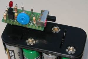
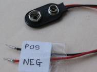
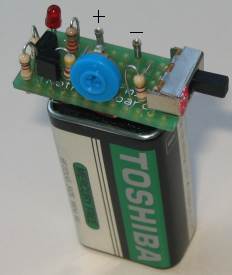
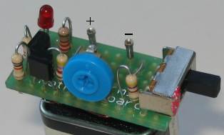
SHAKE TIC TAC LED TORCH |
|
FADING LED |
|
MAINS NIGHT LIGHT |
|
RANDOM BLINKING LEDS |
|
HEX BUG
|
|
PWM CONTROLLER |
|
LIMIT SWITCHES |
|
WAILING SIREN |
|
WHOOP-WHOOP WAILING SIREN
|
|
MODEL RAILWAY TIME
For those who want the circuit to take
less current, here is a version using a Hex Schmitt Trigger chip: |
|
SLOW START-STOP
|
|
VOLTAGE MULTIPLIERS |
|
CLAP SWITCH |
|
INTERCOM |
|
WARNING BEACON |
|
PHASE-SHIFT OSCILLATOR also called SINEWAVE
OSCILLATOR |
|
BLOCKING OSCILLATOR also called FLYBACK
OSCILLATOR |
|
LOW VOLTAGE FLASHER |
|
POWER ON |
|
CAR LOOP DETECTOR |
|
ALARM USING 4-BUTTONS |
|
AUDIO AMPLIFIER (mini) |
|
CAPACITOR DISCHARGE UNIT MkII (CDU2) |
|
CAPACITOR DISCHARGE UNIT MkII (CDU2) -
modification
|
|
CAPACITOR DISCHARGE UNIT FOR KATO POINTS
|
|
PHONE BUG see also Phone
Transmitter 1 and 2 (1-100 circuits) |
|
CODE LOCK |
|
LEDS SHOW RELAY STATE |
|
VOLTAGE DOUBLER
DYNAMO VOLTAGE DOUBLER
BATTERY-CHARGER DOUBLER
|
Adjustable High Current Regulated Power Supply |
|
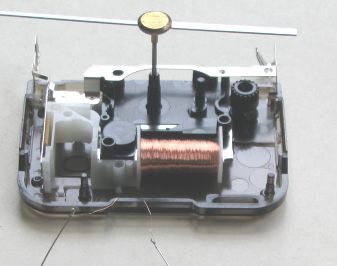
INDUCTIVELY COUPLED POWER SUPPLY
This circuit is from an Interplak Model PB-12 electric toothbrush. A coil in the charging base (always plugged in and on) couples to a mating coil in the hand unit to form a step down transformer. The MPSA44 transistor is used as an oscillator at about 60 kHz which results in much more efficient energy transfer via the air core coupling than if the system were run at 50 or 60Hz. The amplitude of the oscillations varies with the full wave rectified 100Hz or 120Hz unfiltered DC.  The battery charger is nothing more than a diode to rectify the signal from the 120 turn coil in the charging base. Thus the battery is in constant trickle charge as long as the hand unit is in the base. The battery pack is a pair of 600mAhr AA NiCd cells. |
|
POWERING A LED Sometimes the output of a gate does not have sufficient current to illuminate a LED to full brightness. Here are two circuits. The circuits illuminate the LED when the output signal is HIGH. Both circuits operate the same and have the same effect on loading the output of the gate.  |
|
NiCd BATTERY CHARGER This NiCd battery charger can charge up to 8 NiCd cells connected in series. This number can be increased if the power supply is increased by 1.65v for each additional cell. If the BD679 is mounted on a good heatsink, the input voltage can be increased to a maximum of 25v. The circuit does not discharge the battery if the charger is disconnected from the power supply. Usually NiCd cells must be charged at the 14 hour rate. This is a charging current of 10% of the capacity of the cell for 14 hours. This applies to a nearly flat cell. For example, a 600 mAh cell is charged at 60mA for 14 hours. If the charging current is too high it will damage the cell. The level of charging current is controlled by the 1k pot from 0mA to 600mA. The BC557 is turned on when NiCd cells are connected with the right polarity. If you cannot obtain a BD679, replace it with any NPN medium power Darlington transistor having a minimum voltage of 30v and a current capability of 2A. By lowering the value of the 1 ohm resistor to 0.5 ohm, the maximum output current can be increased to 1A.
|
|
CRYSTAL TESTER This circuit will test crystals from 1MHz to 30MHz. When the crystal oscillates, the output will pass through the 1n capacitor to the two diodes. These will charge the 4n7 and turn on the second transistor. This will cause the LED to illuminate.
|
|
LOW VOLTAGE CUT-OUT This circuit will detect when the voltage of a 12v battery reaches a low level. This is to prevent deep-discharge or maybe to prevent a vehicle battery becoming discharged to a point where it will not start a vehicle. This circuit is different to anything previously presented. It has HYSTERESIS. Hysteresis is a feature where the upper and lower detection-points are separated by a gap. Normally, the circuit will deactivate the relay when the voltage is 10v and when the load is removed. The battery voltage will rise slightly by as little as 50mV and turn the circuit ON again. This is called "Hunting." The off/on timing has been reduced by adding the 100u. But to prevent this totally from occurring, a 10R to 47R is placed in the emitter lead. The circuit will turn off at 10v but will not turn back on until 10.6v when a 33R is in the emitter. The value of this resistor and the turn-on and turn-off voltages will also depend on the resistance of the relay.
|
|
THE DARLINGTON TRANSISTOR Normally a single transistor-stage produces a gain of about 100. If you require a very high gain, two stages can be used. Two transistors can be connected connected in many ways and the simplest is DIRECT COUPLING. This is shown in the circuit below. An even simpler method is to combine two transistors in one package to form a single transistor with very high gain, called DARLINGTON TRANSISTOR. These are available as: BD679 NPN-Darlington 2N6284 NPN-Darlington BC879 NPN-Darlington BC880 PNP-Darlington TIP122 NPN-Darlington TIP127 PNP-Darlington These devices consist of two NPN or PNP transistors but the same result can be obtained by using a PNP/NPN pair. This is called a Sziklai pair. This arrangement will have to be created with two separate transistors. The Darlington transistor can also be referred to as: "Super Transistor, Super Alpha Pair, Sziklai pair, Complementary Pair, Darlington transistors have a gain of 1,000 to 30,000. When the gain is 1,000:1 an input of 1mA will produce a current of 1 amp in the collector-emitter circuit. The only disadvantage of a Darlington Transistor is the minimum voltage between collector-emitter when fully saturated. It is 0.6v to 1.5v depending on the current through the transistor. A normal transistor has a collector-emitter voltage (when saturated) of 0.2v to 0.5v. The higher voltage means the transistor will heat up more and requires good heatsinking. In addition, a Darlington transistor needs 1.2v between base and emitter before it will turn on. A Sziklai pair only requires 0.6v for it to turn on.
|
|
PIC PROGRAMMER The simplest programmer to program PIC chips is connected to your computer via the serial port. This is a 9-pin plug/socket arrangement called a SUB-D9 with the male plug on the computer and female on a lead that plugs into the computer. The signals that normally appear on the pins are primary designed to talk to a modem but we use the voltages and the voltage-levels to power a programmer. The voltages on the pins are On or Off. On (binary value "1") means the pin is between -3 and -25 volts, while Off (binary value "0") means it is between +3 and +25 volts, depending on the computer. But many serial ports produce voltages of only +8v and -8V and the programmer circuit uses this to produce a voltage of about 13.5v to put the PIC chip into programming mode. This is the minimum voltage for the programmer to work. Any computers with a lower voltage cannot be used. That's why the circuit looks so unusual. It is combining voltages to produce 13v5. Here are two circuits. The first circuit is used in our PIC PROGRAMMER - 12 parts project. Circuit 2 uses more components to produce the same result and circuit 3 uses less components.
|
|
FLUORESCENT INVERTER The simple circuit will drive up to two 20watt fluoro tubes from a 12v supply. The circuit also has a brightness adjustment to reduce the current from the battery. See Fluorescent Inverter article for more details.
5 watt CFL Driver
|
|
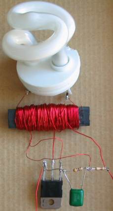
ZAPPER - 160v This project will give you a REAL SHOCK. It produces up to 160v and outputs this voltage for a very short period of time. The components are taken from an old CFL (Compact Fluorescent Lamp) as the transistors are high voltage types and the 1u5 electro @400v can also be taken from the CFL as well as the ferrite core for the transformer. The CFL has a 1.5mH choke with a DC resistance of 4 ohms. This resistance is too low for our circuit and the wire is removed and the core rewound with 50 turns for the feedback winding and 300 turns of 0.1mm wire to produce a winding with a resistance of about 10 ohms for the primary. The oscillator is "flyback" design that produces spikes of about 160v and these are fed to a high-speed diode (two 1N4148 diodes in series) to charge a 1u5 electrolytic to about 160v. If you put your fingers across the electrolytic you will hardly feel the voltage. You might get a very tiny tingle at the end of your fingers. But if this voltage is delivered, then turned off, you get an enormous shock and you pull yours fingers off the touch pads. That's what the other part of the circuit does. It turns on a high-voltage transistor for a very short period of time and this is what makes the circuit so effective.  |
|
TELEPHONE AMPLIFIER This amplifier circuit is used in all home telephones to amplify the signal from the line to the earpiece. The voltage is taken from the line via a bridge that delivers a positive rail, no matter how the phone wires are connected. A 600 ohm to 600ohm standard telephone transformer is used to pick off a signal from the phone line and this is passed through capacitors and resistors to the input of the amplifier. Negative feedback is provided by a 15k and 1n2 capacitor. The operating point for the amplifier is set by the 100k pot and this serves to provide an effect on the gain of the amplifier and thus the volume. This circuit is only connected to the line AFTER the phone has been "picked up." Once you "hang up" you must also disconnect this circuit from the phone line as it will "hang onto" the line due to the 12v zener and also due to the current it takes. This is not an "automatic circuit" It must be connected and removed manually.  |
|
VHF AERIAL AMPLIFIER This amplifier circuit can be used to amplify VHF television signals. The gain is between 5dB and 28dB. 300ohm twin feeder can be used for the In/Out leads.  |
|
CAR LIGHTS ALERT This circuit will alert the driver if the lights have been left on. A warning sound will be emitted from the 12v buzzer when the driver's door is opened and the lights are on.  |
|
How a PIEZO BUZZER WORKS A Piezo Buzzer contains a transistor, coil, and piezo diaphragm and produces sound when a voltage is applied. The buzzer in the circuit above is a PIEZO BUZZER. 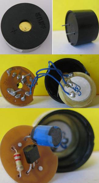
|
|
PIEZO BEEPER This circuit turns a loud piezo siren or screamer into a beep-beep-beep or chirping sound. The 10u and 4k7 produce the timing section that "shuts-off" the oscillator to produce the short beep. You need a piezo diaphragm with feedback tab for this circuit. 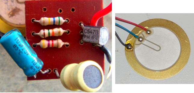
|
MAINS DETECTOR
 This circuit detects the "Active" wire of 110v AC or 240v AC via a probe and does not require "continuity." This makes it a safe detector. It uses the capacitance of your body to create current flow in the detecting part of the circuit and the sensitivity will depend on how you hold the insulating case of the project. No components of the circuit must be exposed as this will result in ELECTROCUTION. |
SIMPLEST FM BUG  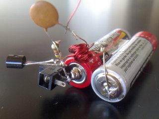 This circuit is the simplest FM circuit you can get. It has no microphone but the coil is so MICROPHONIC that it will pick up noises in the room via vibrations on a table. The circuit does not have any section that determines the frequency. In the next circuit and all those that follow, the section that determines the frequency of operation is called the TUNED CIRCUIT or TANK CIRCUIT and consists of a coil and capacitor. This circuit does not have this feature. The transistor turns on via the 47k and this puts a pulse through the 15 turn winding. The magnetic flux from this winding passes through the 6 turn winding and into the base of the transistor via the 22n capacitor. This pulse is amplified by the transistor and the circuit is kept active. The frequency is determined by the 6 turn coil. By moving the turns together, the frequency will decrease. The circuit transmits at 90MHz. It has a very poor range and consumes 16mA. The coil is wound on a 3mm drill and uses 0.5mm wire. |
A GOOD ONE-TRANSISTOR
CIRCUIT
 This circuit uses a TUNED CIRCUIT or TANK CIRCUIT to create the operating frequency. For best performance the circuit should be built on a PC board with all components fitted close to each other. The photo below shows the components on a PC board: 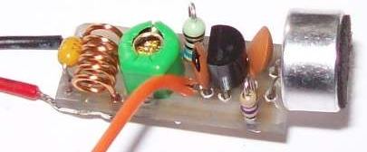
|
AN IMPROVED DESIGN This design uses a "slug tuned coil" to set the frequency. This means the slug can be screwed in and out of the coil. This type of circuit does not offer any improvement in stability over the previous circuit. (In later circuits we will show how to improve stability. The main way to improve stability is to add a "buffer" stage. This separates the oscillator stage from the output.) The antenna is connected to the collector of the transistor and this "loads" the circuit and will cause drift if the bug is touched. The range of this circuit is about 200 metres and current consumption is about 7mA. The microphone has been separated from the oscillator and this allows the gain of the microphone to be set via the 22k resistor. Lowering the resistor will make the microphone more sensitive. This circuit is the best you can get with one transistor. |
MORE STABILITY If you want more stability, the antenna can be tapped off the top of the tank circuit. This actually does two things. It keeps the antenna away from the highly active collector and turns the coil into an auto-transformer where the energy from the 8 turns is passed to a single turn. This effectively increases the current into the antenna. And that is exactly what we want. The range is not as far but the stability is better. The frequency will not drift as much when the bug is held. As the tap is taken towards the collector, the output increase but the stability deceases. |
|
2-TRANSISTOR CIRCUIT The next progressive step is to add a transistor to give the electret microphone more sensitivity. The electret microphone contains a Field Effect Transistor and you can consider it to be a stage of amplification. That's why the electret microphone has a very good output. A further stage of amplification will give the bug extremely good sensitivity and you will be able to pick up the sound of a pin dropping on a wooden floor. Many of the 1 transistor circuits over-drive the microphone and this will create a noise like bacon and eggs frying. The microphone's used by Talking Electronics require a load resistor of 47k for a 6v supply and 22k for a 3v supply. The voltage across the microphone is about 300mV to 600mV. Only a very simple self-biasing common-emitter stage is needed. This will give a gain of approx 70 for a 3v supply. The circuit below shows this audio amplifier, added to the previous transmitter circuit. This circuit is the best design using 2 transistors on a 3v supply. The circuit takes about 7mA and produces a range of about 200 - 400metres.  Five points to note in the circuit above: 1. The tank circuit has a fixed 39p and is adjusted by a 2-10p trimmer. The coil is stretched to get the desired position on the band and the trimmer fine tunes the location. 2. The microphone coupling is a 22n ceramic. This value is sufficient as its capacitive reactance at 3-4kHz is about 4k and the input to the audio stage is fairly high, as noted by the 1M on the base. 3. The 1u between the audio stage and oscillator is needed as the base has a lower impedance as noted by the 47k base-bias resistor. 4. The 22n across the power rails is needed to keep the rails "tight." Its impedance at 100MHz is much less than one ohm and it improves the performance of the oscillator enormously. 5. The coil in the tank circuit is 5 turns of enameled wire with air core. The secret to long range is high activity in the oscillator stage. The tank circuit (made up of the coil and capacitors across it) will produce a voltage higher than the supply voltage due to the effect known as "collapsing magnetic field" and this occurs when the coil collapses and passes its reverse voltage to the capacitor. The antenna is also connected to this point and it receives this high waveform and passes the energy to the atmosphere as electromagnetic radiation. When the circuit is tightly constructed on a PC board, the frequency will not drift very much if the antenna is touched. |
|
THE VOYAGER The only way to get a higher output from two transistors is to increase the supply voltage. The following circuit is available from Talking Electronics as a surface-mount kit, with some components through-hole. The project is called THE VOYAGER.   All the elements of good design have been achieved in this project. The circuit has a slightly higher output than the 3v circuit above, but most of the voltage is lost across the emitter resistor and not converted to RF. The main advantage of this design is being able to connect to a 9v battery. In a technical sense, about half the energy is wasted as the stages actually require about 4v - 5v for maximum output. |
HAND-HELD MICROPHONE This circuit is suitable for a hand-held microphone. It does not have an audio stage but that makes it ideal as a microphone, to prevent feedback. The output has a buffer stage to keep the oscillator away from the antenna. This gives the project the greatest amount of stability -rather than the highest sensitivity. |
|
INCREASING THE RANGE |
|
MORE RANGE The 2N3563 is capable of passing 15mA in the buffer stage and about 30% is delivered as RF. This makes the transmitter capable of delivering about 22mW. |
|
EMITTER TAP |
|
GOING FURTHER The impedance of the output stage is about 1k to 5k, and the impedance of the antenna is about 50 ohms. This creates an enormous matching problem but one effective way is with an RF transformer. An RF transformer is simply a transformer that operates at high frequency. It can be air cored or ferrite cored. The type of ferrite needed for 100MHz is F28. The circuit above uses a small ferrite slug 2.6mm dia x 6mm long, F28 material. To create an output transformer for the circuit above, wind 11 turns onto the slug and 4 turns over the 11 turns. The ferrite core will do two things. Firstly it will pass a high amount of energy from the primary winding to the antenna and secondly it will THE RF TRANSFORMER prevent harmonics passing to the antenna. The transformer approximately doubles the output power of the transmitter. |
|
WATER LEVEL DETECTOR This circuit can be used to automatically keep the header tank filled. It uses a double-pole relay.  CIRCUIT 2 The circuit below is the simplest design and consumes almost zero current when the tank is full. When the water is LOW, the circuit is turned ON via the 100k pot and 10k resistor. When the water reaches the copper wire, the voltage on the base of the first transistor reduces and the current into the Darlington arrangement is too small to keep the relay energised and the motor turns OFF. As the water-level drops, the current into the Darlington pair increases and a point is reached when the relay pulls-in again. 
CIRCUIT 3
|
|
BATTERY CHARGER -
very poor design You will see this circuit on the web, but it is a very poor design as the circuit turns off as soon as the voltage of the battery reaches a pre-determined voltage. However if you use the battery, the charger will not "come on again" as it has been TURNED-OFF. By changing one or two connections, as shown in the next circuit, the charger becomes fully automatic and will keep the battery fully charged, while it is being used. It's simple things like this that make a good design-engineer.
|
|
BATTERY CHARGER -
world's simplest automatic charger This is the world's simplest automatic battery charger. It consists of 6 components, when connected to a 12v DC plug pack. The plug pack must produce more than 15v on no-load (which most plug packs do.) An alternative 15v transformer and a centre-tapped transformer is also shown. A centre-tapped transformer is referred to as: 15v-CT-15v or 15-0-15 The relay and transistor are not critical as the 1k pot is adjusted so the relay drops-out at 13.7v. To improve the "pull-in" and "drop-out" voltages, the 10k can be replaced with a 12v zener. The zener can be made up of two 6v zeners or any combination in series and include ordinary diodes (drop 0.6v). The plug pack can be 300mA, 500mA or 1A and its current rating will depend on the size of the 12v battery you are charging. For a 1.2AH gel cell, the charging current should be 100mA. However, this charger is designed to keep the battery topped-up and it will deliver current in such short bursts, that the charging current is not important. This applies if you are keeping the battery connected while it is being used. In this case the charger will add to the output and deliver some current to the load while charging the battery. If you are charging a flat cell (flat 12v battery - a discharged 12v battery), the current should not be more than 100mA. For a 7AH battery, the current can be 500mA. And for a larger battery, the current can be 1Amp.  Most 12v Plug Packs produce 15v to 16v on NO-LOAD and we are using this feature to charge the battery. We are also using the poor regulation of the plug pack to charge the battery without the plug pack overheating. SETTING UP Connect the charger to a battery and place a digital meter across the battery. Adjust the 1k pot so the relay drops out as soon as the voltage rises to 13.7v. Place a 100R 2watt resistor across the battery and watch the voltage drop. The charger should turn on when the voltage drops to about 12.5v. This voltage is not extremely critical. It happens to be the "hysteresis" of the circuit and is determined by the value of the load in the collector of the transistor. The 22u stops the relay "squealing" or "hunting" when a load is connected to the battery and the charger is charging. As the battery voltage rises, the charging current reduces and just before the relay drops out, it squeals as the voltage rises and falls due to the action of the relay. The 22u prevents this "chattering". To increase the Hysteresis: In other words, decrease the voltage where the circuit cuts-in, add a 270R across the coil of the relay. This will increase the current required by the transistor to activate the relay and thus increase the gap between the two activation points. The pull-in point on the pot will be higher and you will have re-adjust the pot, but the drop-out point will be the same and thus the gap will be wider. In our circuit, the cut-in voltage was 11.5v with a 270R across the relay. Note: No diode is needed across the relay because the transistor is never fully turned off and no back EMF (spike) is produced by the relay. AUTOMATIC BATTERY CHARGER - trickle charger This circuit will automatically keep a battery fully charged with the charge-current reducing when the battery voltage reaches 13.8v. The battery can be used at any time and the charger will maintain full charge.  The transistor acts like a POWER ZENER (with the 13.8v zener on the base) and the supply rail does not rise above 13.8v + 0.6v = 14.4v. The 1N4004 removes the 0.6v to deliver 13.8v to the battery. If the plug pack is replaced with a supply capable of delivering a voltage higher than 16v (on no-load), the 3R3 (3watt) resistor will be needed. The transistor simply removes the charging current from the battery and wastes it as heat. |
BATTERY CHARGER MkII -
a very simple design to keep a battery "topped up." This is a very simple battery charger to keep a battery "nearly fully charged." It consists of 7 components, when connected to a 12v - 18v DC plug pack. The plug pack must produce more than 15v on no-load (which most 12v plug packs do.) For a 1.2AH gel cell, up to a 45Ahr car or boat battery, this charger will keep the battery topped-up and can be connected for many months as the battery will not lose water due to "gassing." The output voltage is 13.2v and this is just enough to keep the battery from discharging, but will take a very long time to charge a battery, if it is flat because a battery produces a "floating charge" of about 13.6v when it is being charged (at a reasonable current) and this charger is only designed to deliver a very small current. There is a slight difference between a "old-fashioned" car battery (commonly called "an accumulator") and a sealed battery called a Gel Cell. The composition of the plates of a gel cell is such that the battery does not begin to "gas" until a high voltage is reached. That is why it can be totally closed and only has rubber bungs that "pop" if gas at high pressure develops due to gross over-charging. That's why the charging voltage must not be too high and when the battery is fully charged, the charging current must drop to a very low level. |
|
GELL CELL BATTERY CHARGER
This circuit will charge gell cell batteries at 300mA or 650mA
or 1.3A, depending on the CURRENT SENSING resistor in the 0v
rail. Adjust the 5k pot for 13.4v out and when the battery
voltage reaches this level, the current will drop to a few
milliamps. The plug pack will need to be upgraded for the 650mA
or 1.3A charge-current. The red LED indicates charging and as
the battery voltage rises, the current-flow decreases. The
maximum is shown below and when it drops about 5%, the LED turns
off and the current gradually drops to almost zero.
|
|
TRANSISTOR TESTER COMBO-22 This circuit uses an IC but it has been placed in this eBook as it is a transistor tester. The circuit uses a single IC to perform 3 tests: Test 1: Place the transistor in any orientation into the three terminals of circuit 1 (below, left) and a red LED will detect the base of a PNP transistor an a green LED will indicate the base of an NPN transistor. Test 2: You now now the base lead and the type of transistor. Place the transistor in Test 2 circuit (top circuit) and when you have fitted the collector and emitter leads correctly (maybe have to swap leads), the red or green LED will come on to prove you have fitted the transistor correctly. Test 3: The transistor can now be fitted in the GAIN SECTION. Select PNP or NPN and turn the pot until the LED illuminates. The value of gain is marked on the PCB that comes with the kit. The kit has ezy clips that clip onto the leads of the transistor to make it easy to use the project. The project also has a probe at one end of the board that produces a square wave - suitable for all sorts of audio testing and some digital testing. Project cost: $22.00 from Talking Electronics.  |
|
LOW MAINS DROPOUT This circuit will turn off a device if the main drops by a say 15v. The actual voltage is adjustable. The first thing to remember is this: The circuit detects the PEAK voltage and this is the voltage of the zener diodes. For 240v mains, the peak is 338v. For a voltage drop of about 12v(RMS), the zener diodes need to have a combined voltage of 320v (you will need 6 x 47v + 1 x 20v + 1 x 18v). The 10k resistor will have about 18v across it and the current will be nearly 2mA. The wattage will be 36mW. For a voltage drop of about 27v(RMS), you will need zeners for a total of 300v by using 6 x 47v + 1 x 18v. The voltage across the 10k resistor will be 38v and the current will be nearly 4mA. The wattage dissipated by the 10k resistor will be 150mW. The 10u prevents very sharp dips or drops from activating the circuit. As the voltage drops, this drop in voltage will be passed directly to the top of the 10k resistor and as the voltage drops, the current into the base of the transistor will reduce. This current is amplified by the transistor and when it is not sufficient to keep the relay activated, it will drop-out.  |
|
PROTECTING THE CONTACTS OF A RELAY:
The contacts of a relay can be protected from the damaging effects of reversing an actuator. The circuit shows a double-pole double-throw relay driving an actuator. The 4 "bridge diodes" around the actuator "squelch" the back-emf from damaging the contacts.  |
|
REDUCING RELAY CHATTER:
To reduce the relay clicking or chattering during the activation of the relay driver transistor, an electrolytic can be placed between the base and 0v rail. In addition an electro can be placed across the relay if there is a possibility of the supply voltage glitching or temporally failing.
|
|
2 TRANSISTOR AMPLIFIER:
This circuit produces a very clean output.  This circuit has a number of features. The two transistors are directly coupled and this produces the maximum gain (or amplification). The other feature is the use of a high impedance (resistance) speaker. A speaker is actually a LINEAR MOTOR and it gets its PULLING POWER from the AMP-TURNS provided by the coil. The amp-turns produce magnetic flux that pushes and pulls against the flux produced by the permanent magnet to move the cone. You can get maximum amp-turns by having a coil with a small number of turns and requiring a high current. Or the same number of amp-turns can be produced by having a coil with lots of turns and only needing to supply a very small current. That's what we have done. You can get more volume, more loudness, with 8 ohm speaker, but when you have 1.5v supply, you will surprised how much volume you will get with 64 ohms. BIASING What happens with the two transistors? The BC557 is turned ON via the 2M2 and the voltage on the base of the BC 557 drops lower than the supply of 1.5v by about 0.6v and this turns ON the BC547 and it is pulled towards the positive rail. This reduces the voltage across the 2M2 and initially it was 0.9v (1.5v - 0.6v). The BC557 finds it very hard to pull the BC547 transistor "up" because the load is the resistance of the speaker. This means the voltage across it will be very small when the circuit is "sitting around" (at rest) and has been measured at 0.05mA. This means the voltage across the speaker will be very small. Now we come to the operation of the circuit. Suppose the input signal is able to fully turn ON the transistor-pair. This means the amplitude will be from 0v to 1.5v - 0.6v = 0.9v That is just 0.9v swing. When the circuit is working, the output of the transistor will be passed directly to the speaker. |
|
3 TRANSISTOR AMPLIFIER:
This circuit produces a very clean output.  |
|
4 TRANSISTOR AMPLIFIER:
This circuit is fully documented in The Transistor Amplifier as Fig 105.  |
|
Vibrating VU
Indicator This circuit can be used to monitor the output of a stereo to warn when the level is too high. The output is a pager motor and will vibrate so you don't have to keep watching VU levels. The first two transistors are connected so an overload in either channel will trigger the pager motor.  No power switch is needed as all transistors are turned OFF when no
audio is being detected.
No power switch is needed as all transistors are turned OFF when no
audio is being detected. |
|
CFL DRIVER This circuit will drive a 5watt Compact Fluorescent Lamp from 12v: 
|
|
VOX These circuits detect audio and operate a relay or produce an output pulse. See full details in: The Transistor Amplifier eBook - under VOX
|
|
OP-AMP WITH 3 TRANSISTORS: This circuit shows how a simple operational amplifier can be made with 3 transistors.
It is really an AC-coupled single-ended class A amp, with an open-loop gain of about 5,000, but as a demonstration-circuit, you can treat it as a simple op-amp. The output is biased at approximately one-half the supply voltage using the combined voltage drops across the two LEDs, the emitter-base voltage of the input transistor and the 1v drop across 1M feedback resistor. The 68k and 4n7 form a compensation network that prevents the circuit from oscillating.
You can configure this op amp as an active filter or as an
oscillator. It drives a load of 1kΩ. The square-wave response
is good at 10kHz, and the output reduces by 3dB at 50kHz. |
|
CAPACITOR TESTER Circuit designed by: Charles Wenzel charles@wenzel.com This circuit will test very small capacitors. The tone from the speaker will change when a capacitor is placed across the test-points "Cx." The operation of the circuit is explained in our eBook: The Transistor Amplifier (high impedance circuit).
|
High bright LED Emergency Light This circuit will illuminate two 1watt High-bright LEDs when the power fails. The charging current is about 20-30mA. It will take about 7 days to charge the battery and this will allow illumination for 5 hours, once per week. A charging current more than 50mA will gradually "dry-out" the battery and shorten its life. If the project is used more than 5 hours per week, the charging current can be increased. The 220R charging resistor can be reduced to 150R or 100R (1watt). |
|
RELAY OFF DELAY
This circuit turns ON a relay when the input is above 2v and the relay turns OFF after 2 seconds when the signal is removed. The OFF delay can be increased or decreased.
|
|
AMPLIFYING A DIGITAL SIGNAL
A Digital signal is only detected as a HIGH or LOW. However if the digital signal does not have sufficient amplitude, it may not be detected AT ALL. This circuit detects a low amplitude signal and produces a high-amplitude signal.
|
|
PIR DETECTOR (see also LED Strip Passage Light) This circuit detects movement and operates a relay. The PIR module has "Sensitivity" and "Time Delay" pots. They can be purchased on eBay for $2.71 including postage!  |
|
DELAY before Turn On .
. .
then turns OFF This circuit turns ON the relay 4 seconds after the power is applied and then turns it OFF after 2 seconds. This is a request from a reader. You will need to change the component values to suit your own timing. When testing the circuit, both electrolytics will be charged after the circuit operates, so you will have to wait any seconds before testing again. Otherwise, discharge both electros to test again.
|
|
10 SECOND DELAY This clever circuit turns on the LED 10 seconds after the power has been switched ON. The secret to its performance is the gain of the transistor. With a gain of 200, the transistor will appear as a 470/200 = 2k3 resistor for the LED and for a 12v supply, this will create a current of 12-1.7 / 2300 = 4.4mA through the LED. The 100u will take about 10 seconds to charge to a point where the base is 1.7v + 0.6v = 2.3v above the 0v rail. When the electro charges to this voltage, the LED starts to come on. The transistor effectively becomes a 2k3 resistor and that's why no additional current-limiting resistor for the LED is needed. The transistor is the current-limiting device!
|
|
FERRET FINDER: This circuit produces a beep-beep-beep at approx 190kHz on a Long Wave Band radio. The transformer (coil) is wound on 10mm dia ferrite rod 10mm long. The primary winding is 0.25mm wire and is 30 turns. The feedback winding is 10 turns The 135t is 0.09mm wire and is called the secondary winding.  PARTS
LIST PARTS
LIST
1 - 10R (100) surface mount resistor 1 - 470k (474) surface mount resistor 1 - 1n surface mount 1 - 100n surface mount 1 - 47u electrolytic surface mount 1 - 1N4148 surface mount diode (A6) 1 - BC848 SM transistor (1G) 5m - 0.09mm wire 1m - 0.25mm wire 1 - 10mm x 12mm ferrite core 3v lithium cell lithium cell holder 1 - Ferret Finder PCB
|
|
FLASHING LIGHTS FOR MODEL RAILWAY CROSSING: A flashing LED is used to create the timing for the flash-rate and the transistor provides the alternate flash for the second set of LEDs. The first circuit comes off the web, but Colin Mitchell doesn't think it will work. See his circuit below.  The top two 1k resistors are current-limiting resistors and can be increased if you want the LEDs to be dull. The 2k2 makes sure the two LEDs are completely turned-off because the flashing LED draws a small current when it is off and this shows in the two LEDs. The lower 1k may need to be reduced to 470R to completely turn the transistor OFF. The other circuit does not have any of these features. The flashing LED has to be an ON-OFF flashing red OR green LED. Not a red-green flashing LED or a RED-GREEN-BLUE flashing LED. The flashing LED actually has an in-built resistor and will work on 2v to 5v. But we are using its feature of "taking a small current" when illuminated and then "taking almost zero current" when not illuminated, to "switch the transistor." You can get the CROSSING LIGHTS plastic mouldings from Talking Electronics. They will take 3mm LEDs. Cost: $6.00 for 2 Crossing Lights with 4 LEDs and 2 metres of fine 0.25mm enamelled wire. You need to "push-out" the red lens and fit the 4 x 3mm red LEDs and carefully solder wires to the LEDs.
|
|
FADE-ON FADE-OFF LED The LEDs in is circuit fade on when the power is applied and fade-off when switched off:  If you just want fade-ON and fade-OFF, this circuit is all you need. The Darlington transistor has internal resistors between the base and emitter of each transistor and these will reduce the input impedance of the transistor considerably. That's why you may have to use fairly low-value resistors on the delay section. Using two separate (normal) transistors will allow the resistor-values to be 100k.
|
|
3-SECOND DELAY:
When this circuit is connected to a supply (from 3v to 12v), the LED turns on and gradually fades after about 3 seconds.  |
|
REPLACING A "POWER POT":
A Power Potentiometer (also called a rheostat) is a potentiometer with a rating of 1watt or more and these can be very expensive. A 10watt pot can cost as much as $25 to $35. This type of pot can be replaced very cheaply by using an ordinary 500R pot and a power transistor. The power pot generally "burns out" when it is at least resistance and this circuit replaces the pot with one slight exception. The circuit does not deliver full rail voltage. The output is about 0.9v below rail voltage. A switch has been included to produce full rail output:
If the Power Pot is a rheostat, it will have two
terminals. One terminal called "A" will go to rail voltage and the
other terminal (the centre terminal - called the wiper) we will call
"B," will go to the load. |
|
CHANGING 24v to 12v: This circuit allows to you charge a 24v project from a 12v charger. It converts the two 12v batteries from series to parallel:  |
|
ZENER
DIODE TESTER All diodes are Zener diodes. For instance a 1N4148 is a 120v zener diode as this is its reverse breakdown voltage. And a zener diode can be used as an ordinary diode in a circuit with a voltage that is below the zener value. For instance, 20v zener diodes can be used in a 12v power supply as the voltage never reaches 20v, and the zener characteristic is never reached. Most diodes have a reverse breakdown voltage above 100v, while most zeners are below 70v. A 24v zener can be created by using two 12v zeners in series and a normal diode has a characteristic voltage of 0.7v. This can be used to increase the voltage of a zener diode by 0.7v. To tests a zener diode you need a power supply about 10v higher than the zener of the diode. Connect the zener across the supply with a 1k to 4k7 resistor and measure the voltage across the diode. If it measures less than 1v, reverse the zener. If the reading is high or low in both directions, the zener is damaged. Here is a zener diode tester. The circuit will test up to 56v zeners.  |
|
LED FADER This circuit was requested by a theatrical group to slowly change the colour of a set of LEDs over a period of 1-2 seconds.  |
|
POINT MOTOR DRIVER
One of the first things (you will want) when expanding a model railway is a second loop or siding. This needs a set of points and if they are distant from the operator, they will have to be electrically operated. There are a number of controllers on the market to change the points and some of them take a very high current. (You can get a low-current Point Motor). The high current is needed because the actuating mechanism is very inefficient, but it must be applied for a very short period of time to prevent the point motor getting too hot. Sometimes a normal switch is used to change the points and if the operator forgets use it correctly, the Point Motor will "burn-out" after a few seconds. To prevent this from happening we have designed the following circuit. It operates the Point Motor for 5mS to 10mS (a very short time) and prevents any damage. You can use a Peco switch (PL23 - about $10.00!!) or an ordinary toggle switch (change-over switch). You can connect to either side of the Point Motor and both contacts of the other side go to 14v to 22v rail.
|
|
COIN COUNTER This circuit was designed for a reader who wanted to change his amusement machine from 3 coins to 4 coins. The circuit can be modified to "divide-by" any value from 2 to 10:  |
|
HEADLIGHT EXTENDER This circuit extends the "ON TIME" for headlights and the circuit does not take any current when the time has expired. When the headlights are switched OFF, the circuit keeps the lights ON for 30 seconds.   The electronics needs 3 connections. The diagram above shows these connections. The first connection is to the 12v side of the battery. The output of the circuit is the emitter of the BD679 transistor and this connects to the relay where the wire from the headlight switch is connected. Finally the circuit connects to the chassis of the car. The "delay-time" is determined by the 100u and 100k resistor. The resistor can be increased to 470k and the capacitor can be increased to 470u. For an adjustable time-delay, use a 500k mini trim pot for the 100k resistor. |
|
TURN INDICATOR ALARM
Many turn indicators in cars, motor bikes and golf carts are not very loud. That's why they get left ON. Here are 2 circuits for you to experiment with and work out which is the best for your application. They all use a piezo buzzer that has an oscillator circuit inside the case and produces a 3kHz annoying tone. We have listed two different types. TypeA produces a constant 3kHz tone that increases with loudness as the voltage increases. TypeB is called a REVERSING BUZZER and produces a beep-beep-beep when a constant DC voltage is applied. The output increases in volume as the voltage increases. Circuit A turns on after 15 seconds to let you know the turn indicator is active. You can use Piezo TypeA to get a beep when the turn light is ON and silence when the light is OFF. Piezo typeB will produce a beep-beep-beep when the light is ON and silence when it is OFF.
Circuit B turns on after 15 seconds and the piezo will increase in loudness.
A piezo buzzer requires about 15mA and operates from 3v to 12v. |
|
SUPPLY VOLTAGE MONITOR: These circuits will monitor supply voltages of ±5v and ±12v. They are not intended to indicate the level of the inputs. The LED will only illuminate when all the voltages are present.  |
|
SOLAR CHARGER
This is a simple circuit to keep a set of NiCads fully charged via a solar panel. The mathematics and the circuit is the same for a 6v or 12v solar panel. The mathematics revolves around CURRENT and not VOLTAGE. Remember: NiCad cells are 1.2v and you will need 5 cells to produce a 6v supply. Ni-MH cells are 1.2v and come in 1,700mAHr and 3,000mAHr (and other capacities). You can recharge ordinary alkaline cells (1.5v) about 50 times. It has about the same capacity as NiCad after the second re-charge. 1. MEASURE THE CURRENT TAKEN BY THE PROJECT Firstly measure the current taken by the project. If it is a constant 10mA, you will need to charge the batteries with 40mA from the solar panel, if we assume the sun shines for 8 hours per day. If the circuit takes 1amp for 1 hour, we need to charge the batteries with 150mA for 8 hours of sunshine. If the circuit takes 500mA for 15 minutes each hour, this is equivalent to a constant 125mA and the charging will have to be 500mA for 8 hours each day. (Even though this is equal to 3Ahr per day, the charging occupies 8 hours and thus the storage only needs to be 2Ahr and 2400mAHr cells can be used). Our mathematics takes into account 80% efficiency in charging the cells. If the NiCad cells are 600mAHr, the maximum charging current is 100mA. If the cells are 2,400mAHr, the maximum charging current is 500mA. This charging current takes into account the fact that the cells will be fully charged towards the end of each day and that's why the current should not be too high. 2. MEASURE THE CHARGING CURRENT Build one of the circuits below and use a 100 ohm (1 watt) resistor for the current-limiting. Connect a multimeter (select 0 - 500mA or 0 - 2Amp range) as shown and measure the current during the day. Take a few readings and work out and average current and approx the length of each day. Every solar panel will deliver a different current and it is not possible to specify any values. That's why you have to take readings. If the current is too high, add another 100 ohm resistor in series. If the current is too low, place a 100 ohm resistor across the first 100 ohm resistor.  |
|
WHITE NOISE GENERATOR:
The basis of a white noise generator is the reverse connection of the base-emitter junction of a transistor as shown in fig A. When the junction sees a voltage above about 5v, it breaks down and this causes the voltage to reduce. The junction ceases to break down and the condition repeats. The result is a waveform of a few millivolts to over 2v, depending on the value of the resistor supplying current to the junction. This noise sounds like "ssssssssss" and can be added to an amplifier to produce all sorts of sound effects including Steam Sound for a model railway. The waveform contains all amplitudes and frequencies from audible up to AM broadcast band. Try the following circuits and see how they work. The supply must be over 5v and preferably more than 8v. That's why many of the circuits specify 12v and higher.  |
|
INTERCOM or TELEPHONE HANDSET You can make your own intercom or replace circuitry in old-style handsets with either of these circuits. Telephone amplifier circuits are completely different to normal amplifier circuits. For a start, they have very high negative feedback to prevent "whistle" and in telephone-speak the circuit is designed so sounds from the earpiece (receiver) are not picked up by the mouthpiece (microphone) and amplified to crate a whistle. Secondly, the load for the amplifier is actually the relay at the exchange and the signal is picked off at the point where the amplifier connects to the relay and sent to the other telephone. This means the supply for both the pre-amplifier and the output stage are on the same wire as the signal to the other phone. The voltage across the first circuit is generated by the 150k turning ON the first BC547 transistor and it "pulls-up" the second transistor (a partial emitter follower). This creates current through the 150R and a voltage is developed across this resistor so that a voltage of approx 15v is developed across the whole circuit. Here are two circuits for the handset:
|
|
38KHz Infrared Link: This circuit is an IR transmitter and IR receiver with a 38kHz detector TSOP 1738 in the receiver. This means the circuit will be immune to ambient light. The motor is activated when the transmitter is turned ON.
|
|
FRIDGE ALARM This circuit will start to produce a sound about 15 seconds after the Light Dependent Resistor detects light:
|
|
FRIDGE ALARM MkII This circuit drives an active piezo buzzer and the circuit takes no current when "sitting around." It will start to produce a sound about 15 seconds after the Light Dependent Resistor detects light. The mini piezo buzzer contains a transistor and inductor to produce a high amplitude oscillator to drive the diaphragm and produce a loud squeal from a supply of 3v to 5v. It will not "turn on" from a slowly rising voltage so the circuit must be designed to rise rapidly when light is detected. That's the purpose of the 2nd and 3rd transistors. They form a high-gain amplifier where the output rises quickly due to the positive feedback provided by the 100n. As soon as the second transistor starts to turn on, it turns on the 3rd transistor and the collector voltage rises. The right-plate of the 100n rises and since the 100n is uncharged, the left plate (lead) rises and increases the voltage and also the current into the base of the second transistor. This makes it turn on more and the action continues very quickly until both transistors are fully turned on. They stay turned on by the voltage (and current) provided by the first transistor. Even though we normally see the second two transistors used as an oscillator, we can use the "rapid turn-on" feature to "kick-start" the piezo and if the middle transistor is provided with too-much voltage (current) on the base, the oscillator feature will not occur because the current into the base is too high and the 100n cannot remove this current during the turn-off period of the cycle. The only unusual feature of this circuit is the oscillator section starts to oscillate at very low amplitude when the first transistor turns off (when the LDR ceases to be illuminated) and a 10u has been added to stop this oscillation so it takes no current when at rest. All the other designs (using a chip), take a small current when at rest and the worst circuit comes from Future Kit, a Thailand based kit company. You can see the discussion in Spot The Mistake Page 17 under FRIDGE ALARM.
|
|
BATTERY-LOW BEEPER
|
|
4 PHONE SECURITY:
See full article on: http://www.electronicsmaker.info
|
|
SOLAR TRACKER:
Click circuit for large image |
|
SIMPLE SONIC DETECTOR:
This is a simple feedback circuit that produces a whistle called a FEEDBACK WHISTLE. This terrible sound was very common in old amplifiers when the microphone was placed too near the speaker. All you need is a high-gain amplifier and a microphone. We have used a piezo diaphragm for both the microphone and speaker. The circuit works best on 12v but will produce good results on 6v or 9v. Vary the distance between the two piezos and turn one over and lift it off the bench to see the different effects and range. Move your hand closer to the piezos and see how the frequency changes. This is due to the length of the wave and if you are located at a distance where the wave does not add to the vibration of the receiving diaphragm, you get silence.  The Circuit produces a FEEDBACK WHISTLE |
MAGNETIC DOOR LOCK DELAY:  This circuit turns OFF the Magnetic Door Lock for 10 second to 30 seconds to allow you to enter. It turns ON after 10 seconds to 30 seconds. |
|
5 SECOND ALARM:
This circuit operates the alarm for 5 seconds, even if the switch is kept closed:
The original reed switch can be used but the
bottom connection to the board must be isolated and re-wired. |
|
MOTOR OVER-RUN This circuit allows the motor to slow-down slowly when it hits the limit switch. Select the value of the components to suit the motor.
|
|
240v INVERTER
You will find lots of inverter circuits on the web, with the following arrangement of 2 transistors and a transformer. 
The problem is the circuit will oscillate at a very
high frequency and the laminations in the transformer are only
designed for a frequency of about 100Hz. |
|
MORE CIRCUITS TO BE ADDED HERE:
|
|
Circuit Symbols The list below covers almost every symbol you will find on an electronic circuit diagram. It allows you to identify a symbol and also draw circuits. It is a handy reference and has some symbols that have never had a symbol before, such as a Flashing LED and electroluminescence panel. Once you have identified a symbol on a diagram you will need to refer to specification sheets to identify each lead on the actual component. The symbol does not identify the actual pins on the device. It only shows the component in the circuit and how it is wired to the other components, such as input line, output, drive lines etc. You cannot relate the shape or size of the symbol with the component you have in your hand or on the circuit-board. Sometimes a component is drawn with each pin in the same place as on the chip etc. But this is rarely the case. Most often there is no relationship between the position of the lines on the circuit and the pins on the component. That’s what makes reading a circuit so difficult. This is very important to remember with transistors, voltage regulators, chips and so many othe r components as the position of the pins on the symbol are not in the same places as the pins or leads on the component and sometimes the pins have different functions according to the manufacturer. Sometimes the pin numbering is different according to the component, such as positive and negative regulators. These are all things you have to be aware of. You must to refer to the manufacturer’s specification sheet to identify each pin, to be sure you have identified them correctly. Colin Mitchell CIRCUIT SYMBOLS Some additional symbols have been added to the following list. See Circuit Symbols on the index of Talking Electronics.com |
|
IC PINOUTS |
![]() to Index
to Index
All the resistor colours:
This is called the "normal" or "3 colour-band" (5%)
range. If you want the 4 colour-band (1%) series, refer to
Talking Electronics website and click: Resistors 1% on the left index. Or
you can use the table below.
 |
 |
 |
 |
 |
 |
 |
 |
|
MAKE ANY RESISTOR VALUE:
There are other ways to combine 2
resistors in parallel or series to get a particular value. The
examples above are just one way. |
|
MAKE ANY CAPACITOR VALUE:
There are other ways to combine 2 capacitors in parallel or series to get a particular value. The examples above are just one way. 4p7 = 4.7p |
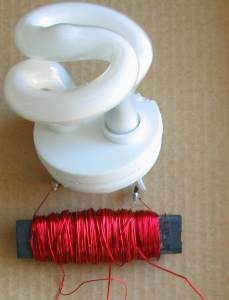 The transformer is made by winding
50 turns and bringing the end out as a "centre-tap." Wind
another 50 turns and this is the "push-pull" primary. The rod can be
round or flat, from an old AM radio. It is called a ferrite rod.
The transformer is made by winding
50 turns and bringing the end out as a "centre-tap." Wind
another 50 turns and this is the "push-pull" primary. The rod can be
round or flat, from an old AM radio. It is called a ferrite rod.
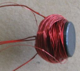 The PC board is 16mm x 14mm.
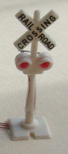
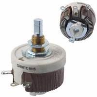
 .
.