save on your computer as .pdf: 1-100 Transistor circuits.pdf
save on your computer as .pdf:
1-100 Transistor circuits.pdf
Go to: 101 - 200 Transistor Circuits
Go to: 100
IC Circuits

See TALKING ELECTRONICS WEBSITE
email Colin Mitchell:
talking@tpg.com.au
| INTRODUCTION This e-book contains 100 transistor circuits. The second part of this e-book will contain a further 100 circuits. Most of them can be made with components from your "junk box" and hopefully you can put them together in less than an hour. The idea of this book is to get you into the fun of putting things together and there's nothing more rewarding than seeing something work. It's amazing what you can do with a few transistors and some additional components. And this is the place to start. Most of the circuits are "stand-alone" and produce a result with as little as 5 parts. We have even provided a simple way to produce your own speaker transformer by winding turns on a piece of ferrite rod. Many components can be obtained from transistor radios, toys and other pieces of discarded equipment you will find all over the place. To save space we have not provided lengthy explanations of how the circuits work. This has already been covered in TALKING ELECTRONICS Basic Electronics Course, and can be obtained on a CD for $10.00 (posted to anywhere in the world) See Talking Electronics website for more details: http://www.talkingelectronics.com Transistor data is at the bottom of this page and a transistor tester circuit is also provided. There are lots of categories and I am sure many of the circuits will be new to you, because some of them have been designed recently by me. Basically there are two types of transistor: PNP and NPN. We have labelled the NPN transistor as BC547. This means you can use ANY NPN transistor, such as 2N2222, BC108, 2N3704, BC337 and hundreds of others. Some circuits use TUN for Transistor Universal NPN and this is the same as our reasoning - the transistor-type is just to let you know it is not critical. BC557 can be replaced by: 2N3906, BC327 and many others. Don't worry too much about the transistor-type. Just make sure it is NPN, it this is the type needed. If it is an unknown transistor-type, you need to identify the leads then put it in the circuit. You have a choice of building a circuit "in the air," or using an experimenter board (solderless breadboard) or a matrix board or even a homemade printed circuit board. The choice is up to you but the idea is to keep the cost to a minimum - so don't buy anything expensive. If you take parts from old equipment it will be best to solder them together "in the air" (as they will not be suitable for placing on a solderless breadboard as the leads will be bent and very short). This way they can be re-used again and again. No matter what you do, I know you will be keen to hear some of the "noisy" circuits in operation. Before you start, the home-made Speaker Transformer project and Transistor Tester are the first things you should look at. If you are starting in electronics, see the World's Simplest Circuit. It shows how a transistor works and three transistors in the 8 Million Gain project will detect microscopic levels of static electricity! You can look through the Index but the names of the projects don't give you a full description of what they do. You need to look at the circuits. And I am sure you will. KIT OF PARTS
Don't think transistor technology is obsolete. Many complex circuits
have one or more transistors to act as buffers, amplifiers or to connect
one block to another. It is absolutely essential to understand this area
of electronics if you want to carry out design-work or build a simple
circuit to carry out a task. Here's an Indian eBook of 270 Circuits:
Some circuits work, some don't, some are
poorly designed and some use components that you cannot obtain.
THEORY
Read the full article
HERE
(the Transistor Amplifier eBook)
Diagram "A" shows an NPN transistor with the
legs covering the symbol showing the name for each lead. Read the full article HERE
|
|
||||
|
|
|
RESISTOR COLOUR CODE
|
|
SAFE 240v SUPPLY When working on any project that connects to the "mains," it is important to take all precautions to prevent electrocution. This project provides 240v AC but the current it limited to 60mA if a 15 watt transformer is used. Although the output can produce a nasty shock and the voltage will kill you, the circuit provides isolation from the mains and if a short-circuit occurs, it will not blow a fuse, but the transformers will get very hot as start to buzz. You can use any two identical transformers and the wattage of either transformer will determine the maximum output wattage. If you don't use identical transformers, the output voltage will be higher or lower than the "mains" voltage and the wattage will be determined by the smaller transformer.
This arrangement is not perfectly safe, but is the best you can get when working on projects such as switch-mode power supplies, capacitor-fed down-lights etc. |
|
RECHARGEABLE BATTERY CAPACITY This simple circuit tests the capacity of a rechargeable cell. Connect a 4R7 (yellow-purple-gold-gold) resistor across the terminals of a clock mechanism and fit a fully charged rechargeable cell. Set the hands to 12 O'Clock and the clock will let you know how long the cell lasted until the voltage reached about 0.8v. Now fit another cell and see how long it lasts. You cannot work out the exact capacity of a cell but you can compare one cell with another. The initial current is about 250mA for a 1.2v cell.
|
|
BATTERY CAPACITY TESTER TEST FAKE CELLS !! This circuit tests the capacity of a rechargeable cell. Lots of cells are FAKE. Just like the UltraFire cell below. It weights 30gms !! You cannot get 6amp-hr capacity into 30gms!!
But what is the capacity of the cell? Our cell had less than
0.5
amp-hr. A Li-Ion cell must be charged on a charger that cuts off when the voltage reaches about 4.2v. If you charge a cell from a variable power supply and do not monitor the terminal voltage of the cell, it will rise to over 5.5v and get damaged. |
|
BLOWN FUSE INDICATOR This circuit indicates when a fuse is "blown." 
|
|
PLANT NEEDS WATERING This circuit indicates when the soil is dry and the plant needs watering. The circuit does not have a current-limiting resistor because the base resistor is very high and the current through the transistor is only 2mA. Don't change the supply voltage or the 220k as these two values are correct for this circuit.  |
|
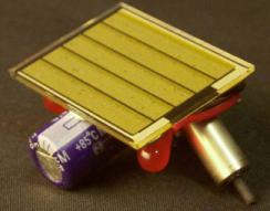
THE SOLAR PANEL This will clear-up a lot of mysteries of the solar panel. Many solar panels produce 16v - 18v when lightly loaded, while other 12v solar panels will not charge a 12v battery. Some panels say "nominal voltage," some do not give any value other than 6v or 12v, and some specify the wrong voltage. You can't work with vague specifications. You need to know accurate details to charge a battery from a solar panel. There are 3 things you have to know before buying a panel or connecting a panel to a battery. 1. The UNLOADED VOLTAGE. 2. The voltage of the panel when delivering the rated current. Called the RATED VOLTAGE 3. The CURRENT. 1. The Unloaded Voltage is the voltage produced by the panel when it is lightly loaded. This voltage is very important because a 12v battery will produce a "floating voltage" of about 15v when it is fully charged and it will gradually rise to this voltage during the charging period. This means the panel must be able to deliver more than 15v so it will charge a 12v battery. Sometimes there is a diode and a charging circuit between the panel and battery and these devices will drop a small voltage, so the panel must produce a voltage high enough to allow for them. The Unloaded Voltage can sometimes be determined by counting the number of cells on the panel as each cell will produce 0.6v. If you cannot see the individual cells, use a multimeter to read the voltage under good illumination and watch the voltage rise. You can place a 100 ohm resistor across the panel to take readings. 2. The RATED VOLTAGE is the guaranteed voltage the panel will deliver when full current is flowing. This can also be called the Nominal Voltage, however don't take anything for certain. Take readings of your own. The Rated Voltage (and current ) is produced when the panel receives bright sunlight. This may occur for only a very small portion of the day. You can clearly see the 11 cells of this panel and it produces 6.6v when lightly loaded. It will barely produce 6v when loaded and this is NOT ENOUGH to charge a 6v battery.  This panel claims to be 18v, but it clearly only produces 14.4v. This is not suitable for charging a 12v battery. When you add a protection diode, the output voltage will be 13.8v. A flat battery being charged will reach 13.8v very quickly and it will not be charged any further. That's why the output voltage of a panel is so important. 
3. The Rated Current is the maximum current the
panel will produce when receiving full sunlight.
CHARGE CURRENT
Connect a 22R 0.25 watt resistor in
series with the battery and hold your finger on the resistor. The
resistor will get very hot if 100mA or more is flowing. |
HIGH-LOW VOLTAGE CUT-OUT This circuit will turn off the relay when the voltage is above or below the "set-points."; You need either a variable power supply or a 12v battery and an extra 1.5v battery. Turn the LOW voltage cutout trim pot to mid way and connect the 13.5v supply. Turn the HIGH voltage trim pot to the high end and the relay will turn off. Now turn the 1.5v battery around the other way and adjust the LOW voltage trim pot to the 10.5v supply. |
See resistors from 0.22ohm to 22M in full colour at bottom of this page and another resistor table
|
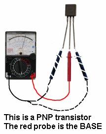
TESTING AN unknown TRANSISTOR The first thing you may want to do is test an unknown transistor for COLLECTOR, BASE AND EMITTER. You also need to know if it is NPN or PNP. You need a cheap multimeter called an ANALOGUE METER - a multimeter with a scale and pointer (needle). It will measure resistance values (normally used to test resistors) - (you can also test other components) and Voltage and Current. We use the resistance settings. It may have ranges such as "x10" "x100" "x1k" "x10" Look at the resistance scale on the meter. It will be the top scale. The scale starts at zero on the right and the high values are on the left. This is opposite to all the other scales. . When the two probes are touched together, the needle swings FULL SCALE and reads "ZERO." Adjust the pot on the side of the meter to make the pointer read exactly zero. How to read: "x10" "x100" "x1k" "x10" Up-scale from the zero mark is "1" When the needle swings to this position on the "x10" setting, the value is 10 ohms. When the needle swings to "1" on the "x100" setting, the value is 100 ohms. When the needle swings to "1" on the "x1k" setting, the value is 1,000 ohms = 1k. When the needle swings to "1" on the "x10k" setting, the value is 10,000 ohms = 10k. Use this to work out all the other values on the scale. Resistance values get very close-together (and very inaccurate) at the high end of the scale. [This is just a point to note and does not affect testing a transistor.] Step 1 - FINDING THE BASE and determining NPN or PNP Get an unknown transistor and test it with a multimeter set to "x10" Try the 6 combinations and when you have the black probe on a pin and the red probe touches the other pins and the meter swings nearly full scale, you have an NPN transistor. The black probe is BASE If the red probe touches a pin and the black probe produces a swing on the other two pins, you have a PNP transistor. The red probe is BASE If the needle swings FULL SCALE or if it swings for more than 2 readings, the transistor is FAULTY. 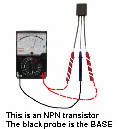
 Step 2 - FINDING THE COLLECTOR and EMITTER Set the meter to "x10k." For an NPN transistor, place the leads on the transistor and when you press hard on the two leads shown in the diagram below, the needle will swing almost full scale. 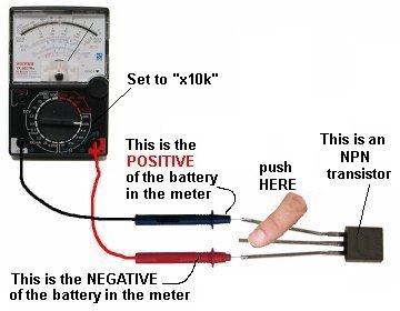 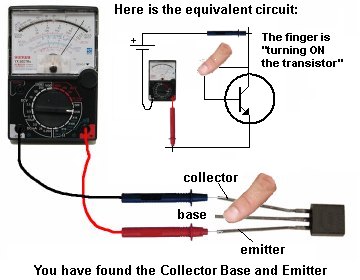 For a PNP transistor, set the meter to "x10k" place the leads on the transistor and when you press hard on the two leads shown in the diagram below, the needle will swing almost full scale. 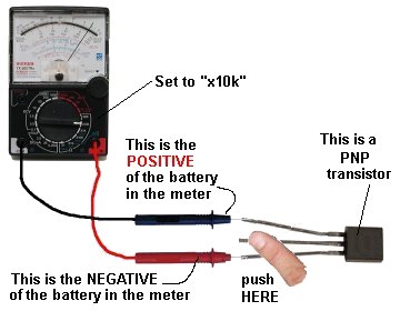 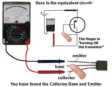 |
|
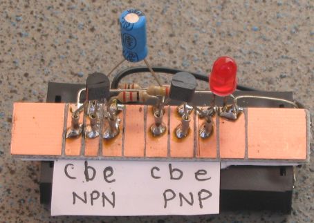
SIMPLEST TRANSISTOR
TESTER The simplest transistor tester uses a 9v battery, 1k resistor and a LED (any colour). Keep trying a transistor in all different combinations until you get one of the circuits below. When you push on the two leads, the LED will get brighter. The transistor will be NPN or PNP and the leads will be identified:  The leads of some transistors will need to be bent so the pins are in the same positions as shown in the diagrams. This helps you see how the transistor is being turned on. This works with NPN, PNP and Darlington transistors.  |
|
||||
 |
TRANSISTOR TESTER - 2 Here is another transistor tester.  This is basically a high gain amplifier with feedback that causes the LED to flash at a rate determined by the 10u and 330k resistor. Remove one of the transistors and insert the unknown transistor. When it is NPN with the pins as shown in the photo, the LED will flash. To turn the unit off, remove one of the transistors. |
|
TRANSISTOR and LED TESTER - 3 Here is another transistor tester. And it also tests LEDs. See the full project: Transistor Tester This circuit is basically a Joule Thief design with the coil (actually a transformer) increasing the 1.5v supply to a higher voltage to illuminate one or two LEDs in series. The "LED Test" terminals uses the full voltage produced by the circuit and it will test any colour LED including a white LED. The two "coils" are wound on a 10mm dia pen with 0.1mm wire (very fine wire). All the components fit on a small PC board. A kit of parts for the project is a available from Talking Electronics for $4.00 plus $3.00 postage.
|
|
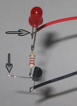 |
WORLDS SIMPLEST CIRCUIT This is the simplest circuit you can get. Any NPN transistor can be used.  Connect the LED, 220 ohm resistor and transistor as shown in the photo. Touch the top point with two fingers of one hand and the lower point with fingers of the other hand and squeeze. The LED will turn on brighter when you squeeze harder. Your body has resistance and when a voltage is present, current will flow though your body (fingers). The transistor is amplifying the current through your fingers about 200 times and this is enough to illuminate the LED. |
 |
SECOND SIMPLEST CIRCUIT
|
|
8 MILLION GAIN! This circuit is so sensitive it will detect "mains hum." Simply move it across any wall and it will detect where the mains cable is located. It has a gain of about 200 x 200 x 200 = 8,000,000 and will also detect static electricity and the presence of your hand without any direct contact. You will be amazed what it detects! There is static electricity EVERYWHERE! The input of this circuit is classified as very high impedance.
|
|
MAINS HUM DETECTOR This simple circuit will detect if a cable is carrying the "Mains." The piezo diaphragm is will let you hear the hum: Do not touch the copper wire. Only place the detector near the plastic covering. It will work at 2cm from the cable.
|
 |
FINDING THE NORTH POLE
The diagrams show that a North Pole will be produced when the positive of a battery is connected to wire wound in the direction shown. This is Flemmings Right Hand Rule and applies to motors, solenoids and coils and anything wound like the turns in the diagram. |
 A two-worm reduction gearbox producing a reduction of 12:1 and 12:1 = 144:1 The gears are in the correct positions to produce the reduction. |
BOXES FOR PROJECTS One of the most difficult things to find is a box for a project. Look in your local "junk" shop, $2.00 shop, fishing shop, and toy shop. And in the medical section, for handy boxes. It's surprising where you will find an ideal box. The photo shows a suitable box for a Logic Probe or other design. It is a toothbrush box. The egg shaped box holds "Tic Tac" mouth sweeteners and the two worm reduction twists a "Chuppa Chub." It cost less than $4.00 and the equivalent reduction in a hobby shop costs up to $16.00!  |
|
|
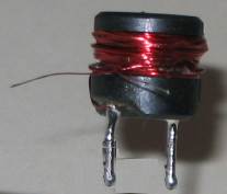
The speaker
transformer is made by
winding 50 turns of 0.25mm wire on a small length of 10mm dia ferrite rod.
|
|
 The circuit uses a flashing LED to flash a super-bright 20,000mcd white LED |
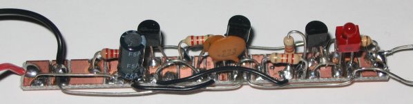
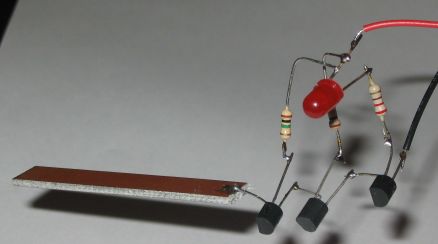
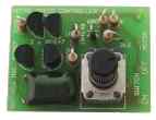
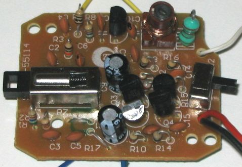
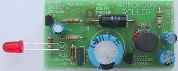
LED FLASHER WITH ONE TRANSISTOR! This is a novel flasher circuit using a single driver transistor that takes its flash-rate from a flashing LED. 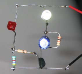 The
flasher in the photo is 3mm. An ordinary LED will not work. The
flasher in the photo is 3mm. An ordinary LED will not work. The flash rate cannot be altered by the brightness of the high-bright white LED can be adjusted by altering the 1k resistor across the 100u electrolytic to 4k7 or 10k. The 1k resistor discharges the 100u so that when the transistor turns on, the charging current into the 100u illuminates the white LED. If a 10k discharge resistor is used, the 100u is not fully discharged and the LED does not flash as bright. All the parts in the photo are in the same places as in the circuit diagram to make it easy to see how the parts are connected. |
 A
normal LED will flash alternately (equal on-off time) with a flashing
LED in this circuit. The 1k pot needs to be adjusted carefully to get
the brightness to a maximum and the reduce the glow when the LED should
be off. A
normal LED will flash alternately (equal on-off time) with a flashing
LED in this circuit. The 1k pot needs to be adjusted carefully to get
the brightness to a maximum and the reduce the glow when the LED should
be off. By using a 5v regulator (LM78L05), the circuit will work from 7v to 16v and can be used on a model train. The secret to the operation of this circuit is the fact that the flashing LED takes slightly more current when it is illuminated. This will produce a very slightly higher voltage across the 1k pot and you need to pick up the change at the 0.55v to 0.6v level and pass this change to the base of the transistor. This is where the transistor changes from OFF to ON and some LEDs work better than others. Some flashing LEDs take the same current when illuminated as when they are NOT ILLUMINATED. You CANNOT use these LEDs. One of the LEDs that worked was clear and flashed RED. You have to test each LED as you cannot guess which LED will work. |
|
|
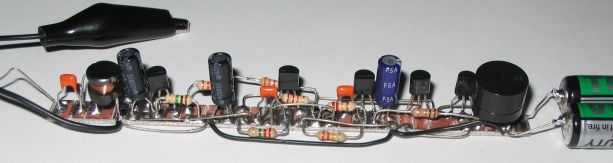
Arc Welder Simulator
for Model Railways This very simple circuit replaces a very complex circuit (one of our previous projects) because all the random flashing is done via a microscopic microcontroller inside the flickering LED.  These LEDs can be purchased on eBay and you can contact
Colin Mitchell for the link. These LEDs can be purchased on eBay and you can contact
Colin Mitchell for the link.
The super-bright white LED flashes much more than the flickering LED because the transistor and the 1u electrolytic picks up the pulses (the waveform) across the 470R resistor and only the main changes in the signal are transferred to the white LED. The 10k is very important as it discharges the 1u to help produce the OFF portion of the waveform. |
|
LED FLASHER These two circuits will flash a LED very bright and consume less than 2mA average current. Both circuits can use a transistor with a larger current capability for the second transistor. The first circuit needs a PNP transistor and the second circuit needs an NPN transistor if a number of LEDs need to be driven. The second circuit is the basis for a simple motor speed control. See the note on how the 330k works, in Flashing Two LEDs below.  |
|
FLASHING TWO LEDS These two circuits will flash two LEDs very bright and consume less than 2mA average current. They require 6v supply. The 330k may need to be 470k to produce flashing on 6v as 330k turns on the first transistor too much and the 10u does not turn the first transistor off a small amount when it becomes fully charged and thus cycling is not produced.  |
 1.5v LED FLASHER |
 LED on 1.5v SUPPLY LED on 1.5v SUPPLYA red LED requires about 1.7v before it will start to illuminate - below this voltage - NOTHING! This circuit takes about 12mA to illuminate a red LED using a single cell, but the interesting feature is the way the LED is illuminated. The 1u electrolytic can be considered to be a 1v cell. (If you want to be technical: it charges to about 1.5v - 0.2v loss due to collector-emitter = 1.3v and a lost of about 0.2v via collector-emitter in diagram B.) It is firstly charged by the 100R resistor and the 3rd transistor (when it is fully turned ON via the 1k base resistor). This is shown in diagram "A." During this time the second transistor is not turned on and that's why we have omitted it from the diagram. When the second transistor is turned ON, the 1v cell is pulled to the 0v rail and the negative of the cell is actually 1v below the 0v rail as shown in diagram "B." The LED sees 1.5v from the battery and about 1v from the electrolytic and this is sufficient to illuminate it. Follow the two voltages to see how they add to 2.5v. |
 |
3v
WHITE LED FLASHER This will flash a white LED, on 3v supply and produce a very bright flash. The circuit produces a voltage higher than 5v if the LED is not in circuit but the LED limits the voltage to its characteristic voltage of 3.2v to 3.6v. The circuit takes about 2mA an is actually a voltage-doubler (voltage incrementer) arrangement. Note the 10k charges the 100u. It does not illuminate the LED because the 100u is charging and the voltage across it is always less than 3v. When the two transistors conduct, the collector of the BC557 rises to rail voltage and pulls the 100u HIGH. The negative of the 100u effectively sits just below the positive rail and the positive of the electro is about 2v higher than this. All the energy in the electro is pumped into the LED to produce a very bright flash. |
|
|
|
|
 |
 |
DUAL 3v
WHITE LED FLASHER This circuit alternately flashes two white LEDs, on a 3v supply and produces a very bright flash. The circuit produces a voltage higher than 5v if the LED is not in circuit but the LED limits the voltage to its characteristic voltage of 3.2v to 3.6v. The circuit takes about 2mA and is actually a voltage-doubler (voltage increaser) arrangement. The 1k charges the 100u and the diode drops 0.6v to prevent the LED from starting to illuminate on 3v. When a transistor conducts, the collector pulls the 100u down towards the 0v rail and the negative of the electro is actually about 2v below the 0v rail. The LED sees 3v + 2v and illuminates very brightly when the voltage reaches about 3.4v. All the energy in the electro is pumped into the LED to produce a very bright flash. |
 |
DUAL 1v5
WHITE LED FLASHER This circuit alternately flashes two white LEDs, on a 1.5v supply and produces a very bright flash. The circuit produces a voltage of about 25v when the LEDs are not connected, but the LEDs reduce this as they have a characteristic voltage-drop across them when they are illuminated. Do not use a supply voltage higher than 1.5v. The circuit takes about 10mA. The transformer consists of 30 turns of very fine wire on a 1.6mm slug 6mm long, but any ferrite bead or slug can be used. The number of turns is not critical. The 1n is important and using any other value or connecting it to the positive line will increase the supply current. Using LEDs other than white will alter the flash-rate considerably and both LEDs must be the same colour. |
 |
LED FLASHES 3 TIMES WHEN POWER IS
APPLIED This circuits uses a FLASHING LED - not an ordinary LED. When the circuit turns ON, the electrolytic is uncharged and the charging-current turns on the transistor. This makes the LED flash. The value of the 47u and 100k will depend on how many times you want the LED to flash. The 1N4148 diode discharges the electrolytic when the power is turned off so the circuit will start immediately the power is applied. This diode is not needed if the circuit is turned off for a long time. |
 |
LED FLASHES FOR 5 SECONDS AFTER
BUTTON IS
RELEASED This circuits uses a FLASHING LED - not an ordinary LED. When the switch is pressed, the LEDs flash for about 5 seconds when the switch is released. and turn off. The circuit takes NO CURRENT after the LEDs have turned OFF. You can experiment with the value of the electrolytics, the 4k7 and 10k to get the result you want. Use red or green LEDs. Only 2 white LEDs can used in each string for 9v supply |
 |
DANCING FLOWER This circuit was taken from a dancing flower. A motor at the base of the flower had a shaft up the stem and when the microphone detected music, the bent shaft made the flower wiggle and move. The circuit will respond to a whistle, music or noise. The operation of this circuit is fully covered HERE |
 |
|
DANCING FLOWER with SPEED CONTROL The Dancing Flower circuit can be combined with the Motor Speed Control circuit to produce a requirement from one of the readers. |
 |
WHITE LINE FOLLOWER This circuit can be used for a toy car to follow a white line. The motor is either a 3v type with gearing to steer the car or a rotary actuator or a servo motor. When equal light is detected by the photo resistors the voltage on the base of the first transistor will be mid rail and the circuit is adjusted via the 2k2 pot so the motor does not receive any voltage. When one of the LDR's receives more (or less) light, the motor is activated. And the same thing happens when the other LDR receives less or more light. |
 |
LED DETECTS LIGHT All LEDs give off light of a particular colour but some LEDs are also able to detect light. Obviously they are not as good as a device that has been specially made to detect light; such as solar cell, photocell, photo resistor, light dependent resistor, photo transistor, photo diode and other photo sensitive devices. A green LED will detect light and a high-bright red LED will respond about 100 times better than a green LED, but the LED in this position in the circuit is classified as very high impedance and it requires a considerable amount of amplification to turn the detection into a worthwhile current-source. All other LEDs respond very poorly and are not worth trying. The accompanying circuit amplifies the output of the LED and enables it to be used for a number of applications. The LED only responds when the light enters the end of the LED and this makes it ideal for solar trackers and any time there is a large difference between the dark and light conditions. It will not detect the light in a room unless the lamp is very close. |
 |
12v RELAY ON 6V SUPPLY This circuit allows a 12v relay to operate on a 6v or 9v supply. Most 12v relays need about 12v to "pull-in" but will "hold" on about 6v. The 220u charges via the 2k2 and bottom diode. When an input above 1.5v is applied to the input of the circuit, both transistors are turned ON and the 5v across the electrolytic causes the negative end of the electro to go below the 0v rail by about 4.5v and this puts about 10v across the relay. Alternatively you can rewind a 12v relay by removing about half the turns. Join up what is left to the terminals. Replace the turns you took off, by connecting them in parallel with the original half, making sure the turns go the same way around |
|
||||
 |
CONSTANT CURRENT SOURCE This circuit provides a constant current to the LED. The LED can be replaced by any other component and the current through it will depend on the value of R2. Suppose R2 is 560R. When 1mA flows through R2, 0.56v will develop across this resistor and begin to turn on the BC547. This will rob the base of BD 679 with turn-on voltage and the transistor turns off slightly. If the supply voltage increases, this will try to increase the current through the circuit. If the current tries to increase, the voltage across R2 increases and the BD 679 turns off more and the additional voltage appears across the BD 679. If R2 is 56R, the current through the circuit will be 10mA. If R2 is 5R6, the current through the circuit will be 100mA - although you cannot pass 100mA through a LED without damaging it. |
 |
LED driver for 12v CAR Here is a simple circuit that will drive any number of LEDs in a single string with a constant 25mA without having to work out the value of the dropper resistor. You can use up to 6 red LED or up to 3 white LEDs with the same circuit. The supply can be 12v to 16v without the brightness altering. |
 |
LED driver IR LEDs in a 12v CAR This circuit will drive up to 7 IR LEDs at a constant current of 70mA from a 12v supply. These LEDs will illuminate ultra-violet sensitive paint to produce a white glow.
|
|
38kHz IR LED Transmitter This circuit will activate a 38kHz receiver module (shown below) to produce a simple IR link to turn on a light or motor.   The only component difficult to obtain is the 38kHz crystal. It is available on Aliexpress for $2.00 for 20 pieces (incl shipping): https://www.aliexpress.com/item/32450746993.html  This
circuit shows how to create an oscillator circuit with a 38kHz crystal. This
circuit shows how to create an oscillator circuit with a 38kHz crystal.
The oscillator is working on less than 0.7v and is injecting its waveform into the base of the second transistor that simple acts as an amplifier. This waveform is then passed to a Darlington Pair to drive an Infra Red LED as hard as possible from a 3v supply and 2R2 current limiting resistor. The circuit has been tested and turns on a 38kHz receiver from 4 metres due to the accuracy of the crystal producing the 38kHz waveform. You can produce the same waveform with a multivibrator circuit but you will need a pot to adjust the frequency to exactly 38kHz. Here is the Talking Electronics IR Receiver Test Module for testing IR Transmitters: See Article HERE I use it all the time to detect IR outputs and 38kHz signals. 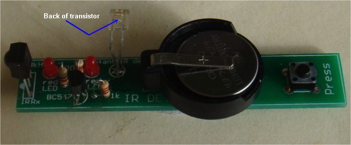 |
  |
CONSTANT CURRENT SOURCE circuits 2 & 3 By rearranging the components in the circuit above, it can be designed to turn ON or OFF via an input. The current through the LED (or LEDs) is determined by the value of R. 5mA R = 120R or 150R 10mA R = 68R 15mA R = 47R 20mA R = 33R 25mA R = 22R or 33R 30mA R = 22R |
 |
 |
CONSTANT CURRENT SOURCE
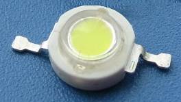
circuit 4 The output will be limited to 100mA by using a red LED and 10R for Re. The output will be limited to 500mA by using a red LED and 2R2 for Re. BC328 - 800mA max Use a BD140 in the first circuit and the output will be limited to 1A by using a red LED and 1R0 for Re. 5watt LEDs (sometimes called "White Big Chip LEDs") have a characteristic voltage across them of 3.2v and draw 1.75amp. 1, 2 or 3 can be connected in series to the second circuit using a heatsinked BD140 transistor. |
 |
ON - OFF VIA MOMENTARY
PUSH-BUTTONS - see Also Push-ON Push-OFF (in 101-200 Circuits) This circuit will supply current to the load RL. The maximum current will depend on the second transistor. The circuit is turned on via the "ON" push button and this action puts a current through the load and thus a voltage develops across the load. This voltage is passed to the PNP transistor and it turns ON. The collector of the PNP keeps the power transistor ON. To turn the circuit OFF, the "OFF" button is pressed momentarily. The 1k between base and emitter of the power transistor prevents the base floating or receiving any slight current from the PNP transistor that would keep the circuit latched ON. The circuit was originally designed by a Professor of Engineering at Penn State University. It had 4 mistakes. So much for testing a circuit!!!! It has been corrected in the circuit on the left. |
 |
SIREN This circuit produces a wailing or siren sound that gradually increases and decreases in frequency as the 100u charges and discharges when the push-button is pressed and released. In other words, the circuit is not automatic. You need to press the button and release it to produce the up/down sound. |
 |
TICKING BOMB This circuit produces a sound similar to a loud clicking clock. The frequency of the tick is adjusted by the 220k pot. The circuit starts by charging the 2u2 and when 0.65v is on the base of the NPN transistor, it starts to turn on. This turns on the BC 557 and the voltage on the collector rises. This pushes the small charge on the 2u2 into the base of the BC547 to turn it on more. This continues when the negative end of the 2u2 is above 0.65v and now the electro starts to charge in the opposite direction until both transistors are fully turned on. The BC 547 receives less current into the base and it starts to turn off. Both transistors turn off very quickly and the cycle starts again. |
|
||||||||||||
TOUCH SWITCH
- LED
|
|
CODE PAD Here is a simple CODE PAD to add to your alarm. It consists of 10 buttons and they must be pressed in a certain order for the output to change. You can see from the circuit how the buttons are pressed and two buttons must be pressed at the same time, the two other buttons at the same time, to gain entry. The operation of this type of pad is very unusual as anyone pressing the buttons by incrementing numbers will not be able to produce the code.
|
 |
SIGNAL INJECTOR This circuit is rich in harmonics and is ideal for testing amplifier circuits. To find a fault in an amplifier, connect the earth clip to the 0v rail and move through each stage, starting at the speaker. An increase in volume should be heard at each preceding stage. This Injector will also go through the IF stages of radios and FM sound sections in TV's. |
 |
LIGHT ALARM - 1 This circuit operates when the Light Dependent Resistor receives light. When no light falls on the LDR, its resistance is high and the transistor driving the speaker is not turned on. When light falls on the LDR its resistance decreases and the collector of the second transistor falls. This turns off the first transistor slightly via the second 100n and the first 100n puts an additional spike into the base of the second transistor. This continues until the second transistor is turned on as hard as it can go. The first 100n is now nearly charged and it cannot keep the second transistor turned on. The second transistor starts to turn off and both transistors swap conditions to produce the second half of the cycle. |
 |
LIGHT ALARM - 2 This circuit is similar to Light Alarm -1 but produces a louder output due to the speaker being connected directly to the circuit. The circuit is basically a high-gain amplifier that is turned on initially by the LDR and then the 10n keeps the circuit turning on until it can turn on no more. The circuit then starts to turn off and eventually turns off completely. The current through the LDR starts the cycle again. |
 LIGHT ALARM - 3 (MOVEMENT DETECTOR) This circuit is very sensitive and can be placed in a room to detect the movement of a person up to 2 metres from the unit. The circuit is basically a high-gain amplifier (made up of the first three transistors) that is turned on by the LDR or photo Darlington transistor. The third transistor charges the 100u via a diode and this delivers turn-on voltage for the oscillator. The LDR has equal sensitivity to the photo transistor in this circuit. |
 |
SOUND TRIGGERED LED This circuit turns on a LED when the microphone detects a loud sound. The "charge-pump" section consists of the 100n, 10k, signal diode and 10u electrolytic. A signal on the collector of the first transistor is passed to the 10u via the diode and this turns on the second transistor, to illuminate the LED. |
 |
SIMPLE LOGIC PROBE This circuit consumes no current when the probe is not touching any circuitry. The reason is the voltage across the green LED, the base-emitter junction of the BC557, plus the voltage across the red LED and base-emitter junction of the BC547 is approx: 2.1v + 0.6v + 1.7v + 0.6v = 5v and this is greater than the supply voltage. When the circuit detects a LOW, the BC557 is turned on and the green LED illuminates. When a HIGH (above 2.3v) is detected, the red LED is illuminated. |
 |
SIMPLE LOGIC PROBE
with PULSE This circuit consumes no current when the probe is not touching any circuitry and the input has a surprisingly HIGH IMPEDANCE. Keep the probe away from stray signals (especially mains hum) as the orange LED will illuminate. When the red LED illuminates, the HIGH is passed through the 1N4148 diode and the third transistor is an emitter-follower. It increases the current-capability of the pulse and charges a 2u2. The 4th transistor increases the capacity of the 2u2 by about 100 times to make it a 220u electro to keep the orange LED illuminated for a few milliseconds after the pulse has ceased. The voltage-drop across the diode and base-emitter junctions of the transistors reduces the voltage on the emitter of the 4th transistor to less than 1v and an extra 1.5v is needed from the supply to illuminate the orange LED. |
 LOGIC PROBE with PULSE This circuit has the advantage of providing a PULSE LED to show when a logic level is HIGH and pulsing at the same time. It can be built for less than $5.00 on a piece of matrix board or on a small strip of copper clad board if you are using surface mount components. The probe will detect a HIGH at 3v and thus the project can be used for 3v, 5v and CMOS circuits. |
 CONTINUITY TESTER This circuit has the advantage of providing a beep when a short-circuit is detected but does not detect the small voltage drop across a diode. This is ideal when testing logic circuits as it is quick and you can listen for the beep while concentrating on the probe. Using a multimeter is much slower. |
 |
TRAIN THROTTLE This circuit is for model train enthusiasts. By adding this circuit to your speed controller box, you will be able to simulate a train starting slowly from rest. Remove the wire-wound rheostat and replace it with a 1k pot. This controls the base of the BC547 and the 2N3055 output is controlled by the BC547. The diodes protect the transistors from reverse polarity from the input and spikes from the rails. |
 |
GUITAR FUZZ The output of a guitar is connected to the input of the Fuzz circuit. The output of this circuit is connected to the input of your amplifier. With the guitar at full volume, this circuit is overdriven and distorts. The distorted signal is then clipped by the diodes and your power amp amplifies the Fuzz effect. |
 |
STRENGTH TESTER This is a simple "staircase" circuit in which the LEDs come on as the resistance between the probes decreases. When the voltage on the base of the first transistor sees 0.6v + 0.6v + 0.6v = 1.8v, LED1 comes on. LEDs 1&2 will come on when the voltage rises a further 0.6v. The amount of pressure needed on the probes to produce a result, depends on the setting of the 200k pot. |
 |
FOG HORN When the push-button is pressed, the 100u will take time to charge and this will provide the rising pitch and volume. When the push-button is released, the level and pitch will die away. This is the characteristic sound of a ship's fog horn. |
 |
HEADS OR TAILS When the push-button is pressed, the circuit will oscillate at a high rate and both LEDs will illuminate. When the push button is released, one of the LEDs will remain illuminated. The 50k is designed to equalise the slightly different values on each half of the circuit and prevent a "bias." |
  |
ROBOT MAN This multivibrator circuit will flash the Robot Man's eyes as shown in the photo. The kit of components is available from Talking Electronics for $8.50 plus postage. Send an email to find out the cost of postage: talking@tpg.com.au |
 |
DYNAMIC MICROPHONE AMPLIFIER This circuit takes the place of an electret microphone. It turns an ordinary mini speaker into a very sensitive microphone. Any NPN transistors such as BC 547 can be used. The circuit will work from 3v to 9v. It is a common-base amplifier and accepts the low impedance of the speaker to produce a gain of more than 100. |
 |
DYNAMIC MICROPHONE AMPLIFIER-2 This circuit is a BOOTSTRAP design. It turns an ordinary mini speaker into a very sensitive microphone. Any NPN transistors such as BC 547 can be used. The circuit will work from 6v to 12v. It has been taken from our Stereo VU Meter project. |
 SCR WITH TRANSISTORS |
 HEE HAW SIREN The circuit consists of two multivibrators. The first multi-vibrator operates at a low frequency and this provides the speed of the change from Hee to Haw. It modifies the voltage to the tone multivibrator, by firstly allowing full voltage to appear at the bottom of the 220R and then a slightly lower voltage when the LED is illuminated. |
 |
MICROPHONE PRE-AMPLIFIER This circuit consists of two directly coupled transistors operating as common-emitter amplifiers. The ratio of the 10k resistor to the 100R sets the gain of the circuit at 100. |
 |
HARTLEY OSCILLATOR The Hartley Oscillator is characterised by an LC circuit in its collector. The base of the transistor is held steady and a small amount of signal is taken from a tapping on the inductor and fed to the emitter to keep the transistor in oscillation. The transformer can be any speaker transformer with centre-tapped primary. The frequency is adjusted by changing the 470p. |
 |
COLPITTS
OSCILLATOR The Colpitts Oscillator is characterised by tapping the mid-point of the capacitive side of the oscillator section. The inductor can be the primary side of a speaker transformer. The feedback comes via the inductor. |
 |
PHASESHIFT
OSCILLATOR The Phaseshift Oscillator is characterised by 3 high-pass filters, creating a 180° phase shift. The output is a sinewave. Take care not to load the output - this will prevent reliable start-up and may stop the circuit from oscillating. Reduced the 3k3 load resistor if the load prevents the circuit oscillating. See Phase Shift Oscillator in second section of 200 Transistor Circuits for a better design. |
 |
DOOR-KNOB ALARM This circuit can be used to detect when someone touches the handle of a door. A loop of bare wire is connected to the point "touch plate" and the project is hung on the door-knob. Anyone touching the metal door-knob will kill the pulses going to the second transistor and it will turn off. This will activate the "high-gain" amplifier/oscillator. The circuit will also work as a "Touch Plate" as it does not rely on mains hum, as many other circuits do. |
|
|
|
 |
 MOTOR SPEED CONTROLLER Most simple motor speed controllers simply reduce the voltage to a motor by introducing a series resistance. This reduces the motor's torque and if the motor is stopped, it will not start again. This circuit detects the pulses of noise produced by the motor to turn the circuit off slightly. If the motor becomes loaded, the amplitude of the pulses decreases and the circuit turns on more to deliver a higher current. |
MOTOR SPEED CONTROL - Circuit 3
 |
 |
ELECTRONIC DRUMS The circuit consists of two "twin-T" oscillators set to a point below oscillation. Touching a Touch Pad will set the circuit into oscillation. Different effects are produced by touching the pads in different ways and a whole range of effects are available. The two 25k pots are adjusted to a point just before oscillation. A "drum roll" can be produced by shifting a finger rapidly across adjacent ground and drum pads. |
 |
LIGHT EXTENDER This circuit is a Courtesy Light Extender for cars. It extends the "ON" time when a door is closed in a car, so the passenger can see where he/she is sitting. When the door switch is opened, the light normally goes off immediately, but the circuit takes over and allows current to flow because the 22u is not charged and the first BC 547 transistor is not turned ON. This turns on the second BC547 via the 100k and the BD679 is also turned on to illuminate the interior light. The 22u gradually charges via the 1M and the first BC547 turns on, robbing the second BC547 of "turn-on" voltage and it starts to turn off the BD679. The 1N4148 discharges the 22u when the door is opened. A 2k2 may needed to be added to completely turn off the globe. |
 |
LIGHT EXTENDER MkII This circuit is a simpler Courtesy Light Extender for cars. It extends the "ON" time when a door is closed in a car. Both circuits perform exactly the same. This circuit is slightly simpler. It uses only a single BC557 and BD679 transistor. A Kit for this project is available from Talking Electronics for $5.20 plus postage. Click Here . |
 |
20 WATT FLUORO INVERTER This circuit will drive a 40 watt fluoro or two 20-watt tubes in series. The transformer is wound on a ferrite rod 10mm dia and 8cm long. The wire diameters are not critical but our prototype used 0.61mm wire for the primary and 0.28mm wire for the secondary and feedback winding. Do not remove the tube when the circuit is operating as the spikes produced by the transformer will damage the transistor. The circuit will take approx 1.5amp on 12v, making it more efficient than running the tubes from the mains. A normal fluoro takes 20 watts for the tube and about 15 watts for the ballast. A Kit for this project is available from Talking Electronics called Fluorescent Lamp Inverter for $12.50 plus postage. Click Here |
 |
6 to 12 WATT FLUORO INVERTER This circuit will drive a 40 watt fluoro or two 20-watt tubes in series but with less brightness than the circuit above and it will take less current. 2 x 20 watt tubes = 900mA to 1.2A and 1 x 20 watt tube 450mA to 900mA depending on pot setting. The transformer is wound on a ferrite rod 10mm dia and 8cm long. The wire diameter is fairly critical and our prototype used 0.28mm wire for all the windings. Do not remove the tube when the circuit is operating as the spikes produced by the transformer will damage the transistor. The pot will adjust the brightness and vary the current consumption. Adjust the pot and select the base-bias resistor to get the same current as our prototype. Heat-sink must be greater than 40sq cm. Use heat-sink compound. |
|
GOLD DETECTOR see also: BFO METAL DETECTOR in "100 IC circuits" SIMPLE BFO METAL LOCATOR in "100 IC circuits" METAL DETECTORS - article This very simple circuit will detect gold or metal or coins at a distance of approx 20cm - depending on the size of the object. The circuit oscillates at approx 140kHz and a harmonic of this frequency is detected by an AM radio. Simply tune the radio until a squeal is detected. When the search coil is placed near a metal object, the frequency of the circuit will change and this will be heard from the speaker. The layout of the circuit is shown and the placement of the radio.
Buying Metal Detector
kit: Metal Detector-1 kit: $14.00
FREE Shipping |
|
METAL DETECTOR MkII
- see the full project:
Metal Detector MkII Metal Detector kit MkII $15.00 plus postage This is a self-contained metal detector with about the same performance as Metal Detector-1 above. All Metal detectors having the principle of detecting a metal object with a coil of about 12cm dia and operating at 100kHz, will have the same performance, no matter how complex the circuit. They all rely on detecting the change in frequency as small as 1Hz or a voltage-change across a coil as small as 1uV. The secret is to produce the largest waveform while loading the coil as lightly as possible. This allows the coil to detect metal at the furthest distance. See more details on Metal Detector MkII  |
|
Nail Finder -
see the full project:
Metal Detector MkII Kits for Metal Detector kit - Nail Finder $17.00 plus postage This project is an extension of Metal Detector MkII, with a small detecting head to find tiny components such as nails and lost components. This is an essential tool for servicemen and anyone trying to find a metal object hidden or buried in timber, soil or mud. 
|
 PHASER GUN This is a very effective circuit. The sound is amazing. You have to build it to appreciate the range of effects it produces. The 50k pot provides the frequency of the sound while the switch provides fast or slow speed. Hear the sounds: (built by a reader) http://www.youtube.com/watch?v=JN_fBZxRpoU&feature=BFa&list=UU2oJeVi1pM3nQy_8X6fFHAA |
 IC RADIO This circuit contains an IC but it looks like a 3-leaded transistor and that's why we have included it here. The IC is called a "Radio in a Chip" and it contains 10 transistors to produce a TRF (tuned Radio Frequency) front end for our project. The 3-transistor amplifier is taken from our SUPER EAR project with the electret microphone removed. The two 1N 4148 diodes produce a constant voltage of 1.3v for the chip as it is designed for a maximum of 1.5v. The "antenna coil" is 60t of 0.25mm wire wound on a 10mm ferrite rod. The tuning capacitor can be any value up to 450p. Note: The YS414 IC is identical to ZN414. See above. |
 5-TRANSISTOR RADIO If you are not able to get the ZN414 IC, this circuit uses two transistors to take the place of the chip. |
 FM TRANSISTOR RADIO This circuit comes from Samuel Budiyanto and also from: http://www.vk2zay.net/article/file/360 and http://www.vk2zay.net/article/89. You must only use 1.5v supply as the gains of the circuit is so high that motor-boating will occur if the voltage is higher. The first transistor is critical. BCxxx transistors do not work. PN3563 does not work. BF173 works. No mention of an aerial in the article. You can try a short wire on the collector of the first transistor. Here is his latest version with some improvements and simplifications:  1. Good selectivity and very sensitive tuning with Tank Circuit. 2. High stability, even when the cell voltage goes down to 0.9v . . . the tuning frequency does not change. 3. Very low current ... just 300uA. 4. Very good sound - bass and treble |
 AUTOMATIC LIGHT This circuit automatically turns on a light when illumination is removed from the LDR. It remains ON for the delay period set by the 2M2 pot. The important feature of this circuit is the building blocks it contains - a delay circuit and Schmitt Trigger. These can be used when designing other circuits. |
 NIGHT LIGHT This circuit activates a relay when illumination falls below a preset level on the Light Dependent Resistor (Photo Cell).  This circuit will drive 30cm strips to 5m strips. Two 5m strips have been tested with this circuit. |
|
PIR LED LIGHT PIR detectors make a wonderful detector to turn on LEDs to illuminate a passage, doorway or path. It has an LDR that only allows the circuit to turn ON at night.  PIR LED LIGHT This circuit can use old cells as it requires less than 20mA to illuminate the 4 LEDs and less than 0.4mA when sitting around. There are a number of different PIR detectors and most of them take 1 minute to settle before detecting IR and turn ON for a short period of time. The 100u (on the emitter of the BC547) increases the turn-ON time to about 4 seconds and some detectors keep outputting a signal while you are in front of the lens. The first transistor increases the current from the PIR module so the 100u can be charged via the 3k3 and the transistor increases the charging current by a factor of about 100 and the second transistor acts as a buffer to deliver current to turn on the LEDs. The 100R and red 100u prevent the PIR re-triggering. This is a great project for "using up" old batteries. A kit for this project is available from Talking Electronics for $6.00 plus $4.50 postage. It is built on a small piece of Matrix Board and includes 4 x super-bright LEDs. Email Colin Mitchell for details.
PIR LED LIGHT using LED STRIP
All these LED panels have inbuilt resistors so they can be connected to 12v supplies. We do not need the inbuilt resistors in this circuit however the resistors cannot be removed.
|
3-LED CHASER by Faraday
s.sh_butterfly@yahoo.com The LEDs in this circuit produce a chasing pattern similar the running LEDs display in video shops. In fact the effect is called: "Running Hole." All transistors will try to come on at the same time when the power is applied, but some will be faster due to their internal characteristics and some will get a different turn-on current due to the exact value of the 22u electrolytics. The last 22u will delay the voltage-rise to the base of the first transistor and make the circuit start reliably. It is very difficult to see where the hole starts and that's why you should build the circuit and investigate it yourself. The circuit can be extended to any number of odd stages as shown in the next circuit, using 5 transistors. 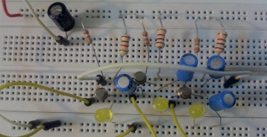 Video by Faraday: 3-LED Chaser mp4 128KB |
|
Another
3-LED CHASER
Here is another 3-LED chaser with an unusual circuit. The transistor is "shorting across" the LEDs to turn them off. The placement of the LEDs on the board is important to produce the rotating effect. Click on the images to get an enlarged version.
|
|
5-LED CHASER This is an extension of the 3-LED Chaser above.  The following circuit produces a slightly different effect because the LEDs are in the emitter. You cannot mix the LED colours.  |
|
3-LED CHASER using FETs This circuit uses FETs. This circuit has been tested with the following two FETs on 6v to 12v with red and white LEDs. The 1M resistor must be reduced to 47k for the 2N7000. Note the different pin-outs for the two FETs.  |
BENCH POWER SUPPLY
|
ADDING A VOLT-METER TO THE BENCH POWER SUPPLY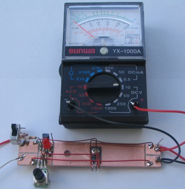 A voltmeter can be added to the Bench Power Supply by using a very low cost multimeter. For less than $10.00 you can get a mini multimeter with 14 ranges, including a 10v range. The multimeter can also be used to monitor current by removing the negative lead and making a new RED lead, fitting it to the "—" of the multimeter and selecting the 500mA range as shown in the photo below: 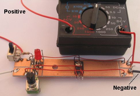 |
MAKING 0-1Amp meter for the BENCH POWER SUPPLY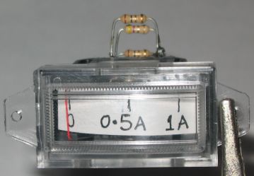 The item in the photo is called a "Movement." A movement is a moving coil with a pointer and no resistors connected to the leads. Any Movement can be converted to an ammeter without any mathematics. Simply solder two 1R resistors (in parallel) across the terminals of any movement and connect it in series with an ammeter on the output of the Bench Power Supply. The second ammeter provides a reference so you can calibrate the movement. Connect a globe and increase the voltage. At 500mA, if the pointer is "up scale" (reading too high) add a trim-resistor. In our case it was 4R7. The three shunt resistors can be clearly seen in the photo. Two 1R and the trim resistor is 4R7. You can get a movement from an old multimeter or they are available in electronics shops as a separate item. The sensitivity does not matter. It can be 20uA or 50uA FSD or any sensitivity. |
|
MAKING A ZENER DIODE and
POWER ZENER
|
12v TRICKLE CHARGER The 12v Trickle Charger circuit uses a TIP3055 power transistor to limit the current to the battery by turning off when the battery voltage reaches approx 14v or if the current rises above 2 amp. The signal to turn off this transistor comes from two other transistors - the BC557 and BC 547. Firstly, the circuit turns on fully via the BD139 and TIP3055. The BC557 and BC 547 do not come into operation at the moment. The current through the 0.47R creates a voltage across it to charge the 22u and this puts a voltage between the base and emitter of the BC547. The transistors turn on slightly and remove some of the turn-on voltage to the BD139 and this turns off the TIP3055 slightly. This is how the 2 amp max is created. As the battery voltage rises, the voltage divider made up of the 1k8 and 39k creates a 0.65v between base and emitter of the BC557 and it starts to turn on at approx 14v. This turns on the BC 547 and it robs the BD136 of "turn-on" voltage and the TIP3055 is nearly fully turned off. All battery chargers in Australia must be earthed. The negative of the output is taken to the earth pin. |
1.5v to 10v INVERTER This very clever circuit will convert 1.5v to 10v to take the place of those expensive 9v batteries and also provide a 5v supply for a microcontroller project. But the clever part is the voltage regulating section. It reduces the current to less than 8mA when no current is being drawn from the output. With a 470R load and 10v, the output current is 20mA and the voltage drop is less than 10mV. The pot will adjust the output voltage from 5.3v to 10v. HOW THE CIRCUIT WORKS The circuit starts by the 100k turning on the BC547 and the BC557 gets turned ON via the 33k resistor. This turns ON the BC337 via the 100R resistor. You will notice the "current-limiting" resistors are getting small and smaller. This is because the transistor-current is getting larger and larger and we want the resistor to pass this higher current. Current flowing through the collector-emitter of the BC337 causes current to flow through the inductor. This current creates expanding flux that cuts all the turns of the inductor and produces a voltage in the OPPOSITE DIRECTION. This voltage OPPOSES the incoming voltage and very little current flows. Over a period of microseconds, this voltage drops a microscopic amount and thus a slightly higher current will flow. The voltage on the collector drops and this change is passed through the 330p to turn on the BC557 MORE. This continues until the BC337 is fully turned ON (by the action of the 330p). The 330p now charges a little more and this reduces the base current in the BC557 and it starts to turn OFF. This action starts to turn OFF the BC337 and very soon we have both transistors fully turned OFF. The BC337 is effectively removed from the circuit and the current flowing through the inductor stops increasing. The magnetic flux stops increasing and the voltage it produces stops IMMEDIATELY. The magnetic flux now does not have any voltage opposing it and it starts to collapse and cut all the turns of the inductor. It does this very quickly because there is no voltage opposing its collapse. The result is a very high voltage in the opposite direction to the applied voltage. What this means is the lower terminal of the inductor produces a voltage that is ADDED to the supply voltage. This voltage can be as high at 100v or more, and is passed through the diode. Even though this voltage is very high, it actually consists of a very high voltage with a very small current. The combination of these two is called ENERGY and it flows into the 100u to charge it. As the voltage on the 100u increases, its voltage is detected by the 4th transistor and when it reaches 10v, the 3rd transistor is turned OFF slightly so the first two transistors are not driven as hard. This is how a stable 10v is produced. |
5v REGULATED SUPPLY FROM 3V This circuit will produce a 5v regulated output from 2 cells (3v). The output current is limited to 50mA but will be ideal for many microcontroller circuits. The output voltage is set to 5v by the 3k9 and 560R resistors, making up a voltage divider network. |
3.3v FROM 5V SUPPLY Here are 3 ways to generate a
3.3v supply: Here are 3 ways to generate a
3.3v supply:Circuit "A" uses two 1.5v cells. This is the cheapest and best way to create a 3v supply. Circuit "B" uses 3 x 1N448 signal diodes to drop 1.8v and produce 3.2v on the output. The 5v supply must be regulated. Circuit "C" produces 3.3v from a 3v3 zener. The 47R limits the output to about 30mA. The 5v can have a small ripple as the zener will create a stable 3v3 output. |
9v SUPPLY FROM 3V You can replace a 9v battery with this circuit. You can replace a 9v battery with this circuit.
The output is about 10.4v on no load and 9.6v @30mA . The advantage is the voltage stays over 9v for the life of the cells. A normal 9v battery drops to 7v very quickly. The output voltage is set to 9-10v by the 6k8 and 390R resistors. The 470R gives the circuit an idling current of about 20mA and the spikes are about 75mV. By increasing the 470R, the quiescent current decreases but the voltage drops more when the current is 30mA. |
27MHz Field Strength Meter
This circuit will test 27MHz transmitters
and show the transmitter is operating when the antenna is connected to
point 1 and the actual frequency of transmission when the antenna is
connected to point 2. |
 |
27MHz TRANSMITTER The transmitter is a very simple crystal oscillator. The heart of the circuit is the tuned circuit consisting of the primary of the transformer and a 10p capacitor. The frequency is adjusted by a ferrite slug in the centre of the coil until it is exactly the same as the crystal. The transistor is configured as a common emitter amplifier. It has a 390R on the emitter for biasing purposes and prevents a high current passing through the transistor as the resistance of the transformer is very low. The "pi" network matches the antenna to the output of the circuit. See full description in 27MHz Links article. |
 27MHz RECEIVER The 27MHz receiver is really a transmitter. It's a very weak transmitter and delivers a low level signal to the surroundings via the antenna. When another signal (from the transmitter) comes in contact with the transmission from the receiver it creates an interference pattern that reflects down the antenna and into the first stage of the receiver. The receiver is a super-regenerative design. It is self-oscillating (or already oscillating) and makes it very sensitive to nearby signals. See full description in 27MHz Links article. |
 |
27MHz TRANSMITTER WITHOUT A CRYSTAL A 27MHz transmitter without a crystal. When a circuit does not have a crystal, the oscillator is said to be "voltage dependent" or "voltage controlled" and when the supply voltage drops, the frequency changes. If the frequency drifts too much, the receiver will not pick up the signal. For this reason, a simple circuit as shown is not recommended. We have only included it as a concept to show how the 27MHz frequency is generated. It produces a tone and this is detected by a receiver. See full description in 27MHz Links article. |
 27MHz TRANSMITTER WITH SQUARE-WAVE OSCILLATOR The circuit consists of two blocks. Block 1is a multivibrator and this has an equal mark/space ratio to turn the RF stage on and off. Block 2 is an RF oscillator. The feedback to keep the stage operating is provided by the 27p capacitor. The frequency-producing items are the coil (made up of the full 7 turns) and the 47p air trimmer. These two items are called a parallel tuned circuit. They are also called a TANK CIRCUIT as they store energy just like a TANK of water and pass it to the antenna. The frequency of the circuit is adjusted by the 47p air trimmer. See full description in 27MHz Links article. |
 27MHz RECEIVER-2 This circuit matches with the 27MHz Transmitter with Square-wave Oscillator. See full description on Talking Electronics website: 27MHz Links article. The receiver frequency is fixed. The transmitter is adjusted to suit the receiver. The 3-27p trimmer is adjusted for maximum gain (10p trimmer and 5p6 in our case) and this is a critical adjustment. The base-emitter junction of the first BC547 sets 0.7v (as it is heavily turned on by the 10k) on the base of the oscillator Q1, and this is fixed. Q1 is very lightly turned on (due to the emitter resistor), and this makes it very sensitive when it is oscillating. Any 27MHz signal from the surroundings will upset the oscillator and any tone in the signal will be passed to the stages for amplification. The coil is 13 turns. It can be replaced with 11 turns of 0.25mm wire on 3mm dia slug 7mm long. Although the original Russian product worked very well, our prototype did not have very good sensitivity. The circuit was very difficult to set-up. Note: When making the 27uH inductor and checking its value on an inductance meter; if the meter does not read low values accurately, put two inductors in series. Measure the first inductor, say 100uH. The two inductors in series will be 127uH as inductors combine just like resistors in series! The result is the addition of the individual values. |
 WALKIE TALKIE Nearly all the components in the 4-transistor circuit are used for both transmitting and receiving. This makes it a very economical design. The frequency-generating stage only needs the crystal to be removed and it becomes a receiver. Next is a three transistor directly coupled audio amplifier with very high gain. The first transistor is a pre-amplifier and the next two are wired as a super-alpha pair, commonly called a Darlington pair to drive the speaker transformer. See full description in 27MHz Links article. |
 |
27MHz TRANSMITTER - 2 CHANNEL This circuit does not use a crystal but has a clever feature of using the two push buttons to turn the circuit on when it is required to transmit. The frequency of the multivibrator is determined by the value of resistance on the base of each transistor. The multivibrator is driven directly from the supply with the forward button and via a 150k for the reverse frequency. The receiver requires a 1kHz tone for forward and 250Hz for reverse. See full description in 27MHz Links article. |
 |
27MHz TRANSMITTER - 4 CHANNEL This circuit uses the same number of components as the 2-Channel circuit above but has 4 channels. The frequency of the multivibrator is determined by the value of resistance on the base of each transistor. A 4 channel receiver has been designed by talking Electronics using a PIC12F628 micro to detect the different frequencies.
See P4 of: |
 |
303MHz TRANSMITTER The transmitter circuit is made up of two building blocks - the 303MHz RF oscillator and the 32kHz crystal controlled oscillator to generate a tone so the receiver does not false-trigger. The 303MHz oscillator consists of a self-oscillating circuit made up of the coil on the PC board and a 9p (9 puff) capacitor. See full description in Wireless Doorbell article. |
|
||||||||||||||||||||||||||||||||||||||||||||||||||||||||||||||||||||||||||||||||||||||||||||||||||||||
  |
BOOM GATE LIGHTS This simple circuit will produce flashing lights for your model railway crossing. It uses one flashing LED and one normal red LED, with a green LED hidden in the background. It can be used somewhere else on your layout but it is needed to produce a voltage drop so the two red LEDs will flash. You cannot get a simpler circuit. The second circuit produces the same effect but the flash-rate is more even. |
|
|
|
 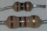 The 1/10th watt resistors used in this circuit, compared with 0.25watt resistors.
|
 5 TRANSISTOR WALKIE TALKIE - 2 Here is another walkie talkie circuit, using slightly different values for some of the components. See the article: 27MHz Transmitters for theory on how these transmitters work. |
 WALKIE TALKIE with LM386 Here is a more up-to-date version of the walkie talkie, using an LM 386 amplifier IC to take the place of 4 transistors. |
 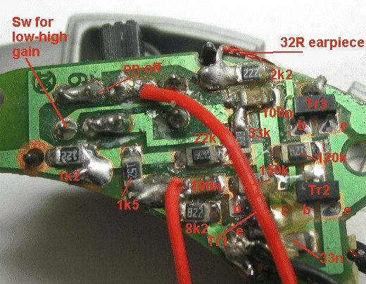 SPY AMPLIFIER This simple circuit will detect very faint sounds and deliver them to a 32 ohm earpiece. The circuit is designed for 1.5v operation and is available from $2.00 shops for less than $5.00 The photo shows the surface-mount components used in its construction. |
 |
HEARING AID 1.5v SUPPLY This simple circuit will detect very faint sounds and deliver them to an 8 ohm earpiece. The circuit is designed for 1.5v operation. The 10k and 10u serve two purposes. They stabilize (bias) the 3 transistors and if a loud noise is detected, the average voltage across the 3R3 increases and this is passed to the 10u to reduce the gain of the first transistor. The RC-time delay is about 1/20th sec. It can be called volume-compression or constant-volume. A really very clever circuit. |
|
HEARING AID 3v SUPPLY This circuit is the same as above but with a few changes that do not make any difference. Adding the 100u across the battery improves the pick-up and clarity ENORMOUSLY. It can be fitted in place of the 100n on the PC board. This module can be bought on eBay for less than $2.00 There are many different designs using very similar circuitry. It's good to buy one of these projects and change the resistor values by placing the same value across each resistor and seeing if the output is altered. This way you can lean about the tolerance for each component. |
 |
HEARING AID with PUSH PULL OUTPUT This circuit will detect very faint sounds and deliver them to an 8 ohm earpiece. It is designed for 3v operation. |
 HEARING AID with CONSTANT VOLUME This is a very handy circuit as it provides constant volume. It is designed for 3v operation. |
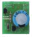
  SOLAR ENGINE This circuit is called Type-1 SE. Low current from a solar cell is stored in a large capacitor and when a preset voltage-level is reached, the energy from the capacitor is released to a motor. For full details on how the circuit works and how to modify it, see: http://www.talkingelectronics.com/projects/Robots/Page2.html |
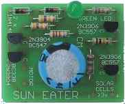
 SUN EATER-I An improved design over Solar Engine circuit above. It has a clever 2-transistor self-latching arrangement to keep the circuit ON until the voltage drops to 1.5v. The circuit turns on at 2.8v. This gives the motor more energy from the electrolytic at each "pulse." For full details on how the circuit works and how to modify it, see: http://www.talkingelectronics.com/projects/Robots/Page2.html |
|
|
  SUN EATER-1A This circuit is an improvement on the Sun Eater I shown above. It works exactly the same except the slight re-arrangement of the components allows an NPN power transistor to be used. One less resistor is needed and one less capacitor but two extra diodes have been added to increase the upper turn-on voltage. For full details on how the circuit works and how to modify it, see: http://www.talkingelectronics.com/projects/Robots/Page2.html |
|
 SOLAR PHOTOVORE The green LEDs cause the Solar Engine on the opposite side to fire and the Solar Photovore turns toward the light source. The motors are two pager "vibe" motors with the weights removed. The 100k pot on the "head" balances the two Solar Engines. If you cannot get the circuit to work with green LEDs, use photo-transistors. For full details on how the circuit works and how to modify it, see: http://www.talkingelectronics.com/projects/Robots/Page4.html |
  FRED Photopopper (Flashing
LED)
FRED Photopopper (Flashing
LED)It is a Photopopper using low-cost components. It uses two red or green flashing LEDs to turn the circuit on when the voltage across the electrolytic has reached about 2.7v. The flashing LEDs change characteristics according to the level of the surrounding light and this turns the circuit into phototropic. For full details on how the circuit works and how to modify it, see: http://www.talkingelectronics.com/projects/Robots/Page6.html |
  ROBO ROLLER ROBO ROLLERThe circuit consists of two building blocks. The Photopopper circuit and a voltage multiplying (or voltage increasing) circuit from a Solar Charger project. For full details on how the circuit works and how to modify it, see: http://www.talkingelectronics.com/projects/Robots/Page7.html |
 SIGNAL BY-PASS SIGNAL BY-PASSThis circuit allows a class-A amplifier to drive a low impedance speaker and has a low quiescent current. The 220R in series with the speaker limits the "wasted" current to about 20mA max as the transistor is generally biased at mid-voltage. However the transistor will be almost directly driving the speaker when a signal is being processed and the only limitation is the ability of the 220R to discharge the 100u during each cycle. The circuit is called a signal by-pass as the signal by-passes the 220R and drives the speaker directly (via the 100u). |
SOUND-TO-LIGHT The LED illuminates when the piezo diaphragm detects sound. Some piezo diaphragms are very sensitive and produce 100mV when whistling at 50cm. Others produce 1mV. You must test them with a CRO. The sensitivity of the diaphragm will determine the sensitivity of the circuit. The following circuit uses an electret microphone:  |
CLAP SWITCH - see also VOX SOUND-TO-LIGHT with Delay By re-arranging the components slightly from the previous circuit, we create a 15 second illumination of the LED. It will be illuminated with the clap of the hands. The quiescent current is about 20uA, allowing 4 AA cells to last a long time. The circuit takes about 20 seconds to reset after the LED goes out. The 100u discharges through the 27k, 100k and 10k resistors. The circuit can also be designed to accept an electret microphone:  CLAP SWITCH "ON-OFF" This circuit turns the LED ON with a clap or short whistle. And a further clap turns it OFF. It uses a speaker as a microphone and the fourth output of the 4017 is used to reset the chip. The 100u on pin 2 upsets the amplifier and prevents it clocking the chip, until the electro either charges or discharges. A buffer transistor can replace the LED to operate a relay. It only requires 2mV signal to activate the circuit.  I have also designed a clap switch using a 555 IC. |
 Above: A 3.5mm switched stereo plug and socket wiring.  MUSIC-TO-COLOUR The LED illuminates when the circuit detects a high amplitude waveform. It can be connected to a "Walkman" or mini radio with earphones. A second channel can be connected to produce a stereo effect. Circuit A consumes less current as the LED is off when no audio is detected. Circuit B pulses the LED brighter when audio is detected. |
|
Why pay $100 for a cable tracer when you can build one for less than $10.00! This type of tracer is used by telephone technicians, electricians and anyone laying, replacing or wiring anything, using long cables, such as intercoms, television or security. Our cable tracer consists of two units. One unit has a multivibrator with an output of 4v p-p at approx 5kHz. This is called the transmitter. The other unit is a very sensitive amplifier with capacitive input for detecting the tone from the transmitter and a magnetic pickup for detecting magnetic lines of force from power cables carrying 240v. This is called the receiver. The circuit also has an inductive loop, made up of a length of wire, to pick up stray signals from power cables, so if one detector does not detect the signal, the other will. Our circuit is nothing like that in the professional unit shown above. |
||||||
 |
LED TORCH with 1.5v SUPPLY This simple circuit will illuminate a super-bright white LED to full brightness with 28mA from a 1.5v cell. The LED is 20,000mcd (20cd @ 15° viewing angle) and has an output of approx 1lumen. The transformer is wound on a small ferrite slug 2.6mm dia and 6mm long. It is made from F29 ferrite material as the circuit operates at a high frequency (100kHz to 500kHz). The efficiency of the circuit revolves around the fact that a LED will produce a very high output when delivered pulses, but the overall current will be less than a steady DC current. BC 337 has a collector-emitter voltage of 45v. (BC338 has 25v collector-emitter voltage rating.) The voltage across the transistor is no more than 4v as the LED absorbs the spikes. Do not remove the LED as the spikes from the transformer will damage the transistor. The circuit will drive 1 or 2 while LEDs in series. |
 |
WHITE LED FLASHER This circuit will flash a super-bright white LED from a 1.5v cell. The transformer is wound on a small ferrite slug 2.6mm dia and 6mm long as shown in a project above. The circuit uses the zener characteristic of the reverse-base-emitter junction of a BC 547 to pass current and flash the LED.
|
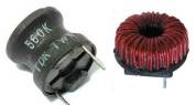
USING A TOROID INDUCTOR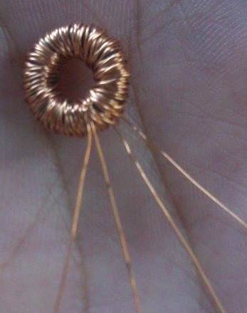 Most of
our circuits use a ferrite rod and NOT a TOROID. A toroid
is a circular core (sometimes called a doughnut or torus or ring or
annulus) and is actually the most efficient type of ferrite
core because none of the flux is lost to the outside surroundings. Most of
our circuits use a ferrite rod and NOT a TOROID. A toroid
is a circular core (sometimes called a doughnut or torus or ring or
annulus) and is actually the most efficient type of ferrite
core because none of the flux is lost to the outside surroundings. BUT if you use a toroid, you MUST work out the amount of flux you will be generating when the transistor is turned ON and this will give you the flux density in the toroid. But this is a very difficult thing to do. If you deliver more flux than the toroid can accept, the expanding flux will not increase at this point in time and the current taken (supplied or delivered) by the transistor will increase ENORMOUSLY and the transistor will be DESTROYED. If you use a ferrite rod, the flux will be lost to the outside air (out the end of the rod) and the abrupt saturation-point will NOT be generated. This means a ferrite rod is a much-more "sloppy" or "loose" or "accommodating" component and is much easier to incorporate into a circuit that has not been mathematically designed. If you want to use a toroid, the only way to "design a circuit" that does not "self-destroy" is to add a lot more turns and gradually remove a few of the turns while feeling the output transistor for temperature-rise or measure the current taken by the circuit. 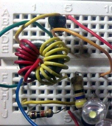 Sometimes
the number of turns will be reduced to 7 turns plus 7 turns for some of
the circuits driving LEDs in the boost converters shown below. Sometimes
the number of turns will be reduced to 7 turns plus 7 turns for some of
the circuits driving LEDs in the boost converters shown below.Why only 7 turns for a toroid? As the transistor turns ON, the 7 turns produces much less flux than 30 turns and the transistor can turn on for a much longer period of time. When it is fully turned ON, the core is just at the point of being fully saturated. At this instant, the flux no-longer expands (increases) and thus the voltage produced in the feedback winding ceases. This is when the "increasing" part of the cycle stops, and the "turn-off" part of the cycle starts. This means the current through the transistor is only a maximum for a very short period of time. That's why you have to experiment yourself and it's only when you get the circuit to work perfectly, that you will LEARN ELECTRONICS. The workings of an inductor are much more complex than you think. |
1v5 WHITE LED DRIVER This circuit will drive a super-bright white LED from a 1.5v cell. The 60 turn inductor is wound on a small ferrite slug 2.6mm dia and 6mm long with 0.25mm wire. The main difference between this circuit and the two circuits above is the use of a single winding and the feedback to produce oscillation comes from a 1n capacitor driving a high gain amplifier made up of two transistors. The feedback is actually positive feedback via the 1n and this turns on the two transistors more and more until finally they are fully turned on and no more feedback signal is passed though the 1n. At this point they start to turn off and the signal through the 1n turns them off more and more until they are fully turned off. The 33k turns on the BC557 to start the cycle again. |
|
 |
LED TORCH - 3v Supply This circuit will drive up to 3 high-bright white LEDs from a 3v supply. (It will also work from 1.5v) The inductor consists of 50 turns on a 1.6mm dia ferrite slug using 0.1mm enamelled wire. This circuit can use a ready-made 33uH choke, making it suitable for mass production |
 |
LED TORCH with ADJUSTABLE BRIGHTNESS This circuit will drive up to 3 high-bright white LEDs from a 3v supply. The circuit has a pot to adjust the brightness to provide optimum brightness for the current you wish to draw from the battery. The transformer is wound on a ferrite slug 2.6mm dia and 6mm long as shown in the LED Torch with 1.5v Supply project. This circuit is a "Boost Converter" meaning the supply is less than the voltage of the LEDs. If the supply is greater than the voltage across the LEDs, they will be damaged. |
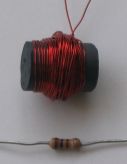  Inductor: 60 turns on 10mm ferrite rod, 15mm long. |
BUCK CONVERTER for HIGH-POWER LED 48mA to 90mA This circuit is a "Buck Converter" meaning the supply is greater than the voltage of the LED. It will drive 1 high-power white LED from a 12v supply and is capable of delivering 48mA when R = 5R6 or 90mA when R = 2R2. The LED is much brighter when using this circuit, compared with a series resistor delivering the same current. But changing R from 5R6 to 2R2 does not double the brightness. It only increases it a small amount. The inductor consists of 60 turns of 0.25mm wire, on a 15mm length of ferrite rod, 10mm diameter. Frequency of operation: approx 1MHz. The circuit is not designed to drive one 20mA LED. This circuit draws the maximum for a BC 338. |
 |
BUCK CONVERTER for HIGH-POWER LED
170mA This circuit is slightly simpler than above but it does not have the feature of being able to adjust the drive-current. The inductor is the same as the photo above but has a feedback winding of 15 turns. Connect the circuit via a 220R resistor and if the LED does not illuminate, reverse the feedback winding. The driver transistor will need a small heatsink. |
 |
BUCK CONVERTER for HIGH-POWER LED
210mA This circuit will drive 1 high-power white LED from a 12v supply and is capable of delivering 210mA. The driver transistor is BD 139 and the details of the inductor are shown above. The voltage across the LED is approx 3.3v - 3.5v The driver transistor will need a small heatsink. The 2R2 can be increased if a lower drive-current is required.
|
 Designed 12-8-2011 |
BUCK CONVERTER for HIGH-POWER LED
250mA - 1watt LED This circuit will drive 1watt white LED from a 12v supply and is capable of delivering 300mA. The driver transistor is BC 327 and the inductor is 70 turns of 0.25mm wire wound on the core of a 10mH inductor. See Inductor to learn how the inductor works. The voltage across the LED is approx 3.3v - 3.5v The 1R is used to measure the mV across it. 300mV equals 300mA LED current. The diode MUST be high speed. A non-high-speed diode increases current 50mA! This circuit is the best design as it does not put peaks of current though the LED. Reduce 390R slightly to increase max. current. |
MAKE YOUR OWN 1-WATT LED
The LEDs are connected in 3 strings of 5 LEDs. Each LED has a characteristic voltage of 3.2v to 3.6v making each chain between 16v and 18v. By selecting the LEDs we have produced 3 chains of 17.5v Five LEDs (in a string) has been done to allow the circuit to be powered by a 12v battery and allow the battery to be charged while the LEDs are illuminating. If only 4 LEDs are in series, the characteristic voltage may be as low as 12.8v and they may be over-driven when the battery is charging. (Even-up the characteristic voltage across each chain by checking the total voltage across them with an 19v supply and 470R dropper resistor.) The transformer is shown above. It is wound on a 10mH choke with the original winding removed. This circuit is called a "boost circuit." It is not designed to drive a single 1-watt LED (a buck circuit is needed). The LEDs in the circuit are 20,000mcd with a viewing angle of 30 degrees (many of the LED specifications use "half angle." You have to test a LED to make sure of the angle). This equates to approximately 4 lumens per LED. The 4-watt CREE LED claims 160 lumens (or 40 lumens per watt). Our design is between 50 - 60 lumens per watt and it is a much-cheaper design.  |
|
18 LEDs using a 3.7v Li-Ion CELL This circuit drives 18 white LEDs from a 3.7v Li-Ion cell. It has been designed by Samuel Budiyanto budiyantosamuel90@gmail.com using components from an old Compact Fluorescent Lamp. No data is available on the 1mH inductor and the circuit has been provided for experimentation purposes ONLY. It is an interesting circuit because the two transistors provide a constant brightness and the BC547 provides feedback to keep the circuit oscillating. The 10k base resistor seems very high but the circuit has been tested for 12 hours on a 1200mA-Hr cell and the brightness remained constant. The brightness is determined by how hard you drive the 2SD882 transistor. It is turned on by the 10k resistor and this will deliver very little current, but since the transistor has a gain of 100 to 300, the collector current will be up to about 100mA. Basically the circuit will over-drive the LEDs and the BC547 will limit the current to the required brightness level. The BC547 transistor has the effect of turning OFF the 2SD at a particular instant in each cycle to reduce the time when it is turned ON. The BC547 gets its "timing" from the 10k and 1k resistors, by the fact that these resistors form a voltage divider to produce a voltage on the base. When the 2SD turns ON, a voltage is developed across the 10R that adds to this voltage but it is delayed slightly by the 1n capacitor. The 1n determines the frequency at which the circuit will oscillate. By experimenting with these 4 components you get the required brightness and this remains constant for the life of the cell. All the LEDs are in series on each string and the brightness will depend on matching each string. By swapping some of the LEDs you will be able to adjust the brightness to make them all emit equally.  |
1-WATT LED - a very good designn
This turns off the BD139 a little more and the current through the inductor reduces. This creates a collapsing flux that produces a voltage across the coil in the opposite direction. This voltage passes via the 1n to turn the BC547 ON and the BD139 is fully turned OFF. The inductor effectively becomes a miniature battery with negative on the lower LED and positive at the anode of the Ultra Fast diode. The voltage produced by the inductor flows through the UF diode and both 1-watt LEDs to give them a spike of high current. The circuit operates at approx 500kHz and this will depend on the inductance of the inductor. The circuit has about 85% efficiency due to the absence of a current-limiting resistor, and shuts off at 4v, thus preventing deep-discharge of the rechargeable cells or 6v battery. The clever part of the circuit is the white LED and two diodes. These form a zener reference to turn the circuit off at 4v. The 10k resistor helps too. The circuit takes 70mA on low brightness and 120mA on HIGH brightness via the brightness-switch. The LEDs actually get 200mA pulses of current and this produces the high brightness. The Inductor The coil or inductor is not critical. You can use a broken antenna rod from an AM radio (or a flat antenna slab) or an inductor from a computer power supply. Look for an inductor with a few turns of thick wire (at least 30) and you won't have to re-wind it. Here are two inductors from surplus outlets: http://www.goldmine-elec-products.com/prodinfo.asp?number=G16521B - 50 cents Here are the surplus inductors:
The cost of surplus is from 10 cents to 50 cents, but you are
sure to find something from a computer power supply.
By using the following idea, the current reduces to 90mA and 70mA and the illumination over a workbench is much better than a single high-power LED. It is much brighter and much nicer to work under. Connect fifteen 5mm LEDs in parallel (I used 20,000mcd LEDs) by soldering them to a double-sided strip of PC board, 10mm wide and 300mm long. Space them at about 20mm. I know you shouldn't connect LEDs in parallel, but the concept works very well in this case. If some of the LEDs have a characteristic high voltage and do not illuminate very brightly, simply replace them and use them later for another strip. You can replace one or both the 1-watt LEDs with a LED Strip, as shown below:
No current-limit resistor. . . why isn't the LED damaged? Here's why the LED isn't damaged: When the BD139 transistor turns ON, current flows through the LEDs and the inductor. This current gradually increases due to the gradual turning-on of the transistor and it is also increasing through the inductor. The inductor also has an effect of slowing-down the "in-rush" of current due to the expanding flux cutting the turns of the coil, so there is a "double-effect" on avoiding a high initial current. That's why there is little chance of damaging the LEDs. When it reaches 65mA, it produces a voltage of .065 x 10 = 650mV across the 10R resistor, but the 1n is pushing against this increase and it may have to rise to 150mA to turn on the BC547. LEDs can withstand 4 times the normal current for very short periods of time and that's what happens in this case. The BD139 is then turned off by the voltage produced by the inductor due to the collapsing magnetic flux and a spike of high current is passed to the LEDs via the high speed diode. During each cycle, the LEDs receive two pulses of high current and this produces a very high brightness with the least amount of energy from the supply. All the components run "cold" and even the 1-watt LEDs are hardly warm. Charging and Discharging This project is designed to use all your old NiCad cells and mobile phone batteries. It doesn't matter if you mix up sizes and type as the circuit takes a low current and shuts off when the voltage is approx 4v for a 6v pack. If you mix up 600mA-Hr cells with 1650mA-Hr, 2,000mA-Hr and 2,400mA-Hr, the lowest capacity cell will determine the operating time. The capacity of a cells is called "C." Normally, a cell is charged at the 14 hour-rate. The charging current is 10% of the capacity. For a 600mA-Hr cell, this is 60mA. In 10 hours it will be fully charged, but charging is not 100% efficient and so we allow another 2 to 4 hours. For a 2,400mA-Hr cell, it is 240mA. If you charge them faster than 14-hr rate, they will get HOT and if they get very hot, they may leak or even explode. But this project is designed to be charged via a solar panel using 100mA to 200mA cells, so nothing will be damaged. Ideally a battery is discharged at C/10 rate. This means the battery will last 10 hours and for a 600mA-Hr cell, this is 60mA. If you discharge it at the "C-rate," it will theoretically last 1 hour and the current will be 600mA. But at 600mA, the cells may only last 45 minutes. If you discharge is at C/5 rate, it will last 5 hours. Our project takes 120mA so no cell will be too-stressed. A 600mA-Hr cell will last about 4-5 hours, while the other cells will last up to 24 hours. Try to keep the capacity of each cell in a "battery-pack" equal. MODIFICATIONS FROM A READER budiyantosamuel90@gmail.com The 390R changed to 1k. The 1n changed to 470p. Replaced the UF4004 with 4 x 1N4148 in parallel. The result is amazing, much brighter! I can't believe it. I put 20 white LEDs in a LED strip... and it works nicely. Much brighter than two 1 Watt LEDs. Colin: If the length of a ferrite rod is too short, the magnetic material will saturate and it will not accept any more current and it will start to produce losses by heating-up. A toroid may work better because it will accept a higher flux density because the magnetic path does not have an air gap. (a ferrite rod is said to have an air-gap at the ends of the rod). That's why a toroid will be smaller than a rod. |
 |
 |
|||||||
BUCK CONVERTER for 3watt LED This circuit drives a 3watt LED. You have to be careful not to damage the LED when setting up the circuit. Add a 10R to the supply rail and hold it in your fingers. Make sure it does not get too hot and monitor the voltage across the resistor. Each 1v represents 100mA. The circuit will work and nothing will be damaged. If the resistor "burns your fingers" you have a short circuit. The BC557 multivibrator has a "mark-to-space ratio" determined by the 22n and 33k, compared to the 100n and 47k, producing about 3:1 The BD679 is turned ON for about 30% of the time. This produces a very bright output, and takes about 170mA for 30% of the time. You cannot measure this current with a meter as it reads the peak value and the reading will be totally false. The only way to view the waveform is on a CRO, and calculate the current. The 100-turn inductor allows the BD679 turn turn ON fully and "separates" the voltage on the emitter of the BC679 from the voltage on the top of the 3watt LED. When the BD679 turns ON, the emitter rises to about 10v. But the top of the LED NEVER rises above 3.6v. The inductor "buffers" or "separates" these two voltages by producing a voltage across the winding equal to 6.4v and that's why the LED is not damaged. When the transistor turns off (for 60% of the time), the magnetic flux produced by the current in the inductor collapses and produces a voltage in the opposite direction. This means the inductor now becomes a miniature battery and for a very short period of time it produces energy to illuminate the LED. The top of the inductor becomes negative and the bottom is positive. The current flows through the LED and through the Ultra High-Speed 1N4004 diode to complete the circuit. Thus the circuit takes advantage of the energy in the inductor. A 500R pot is placed across the LED and a voltage is picked off the pot to turn on a BC547 transistor. This transistor "robs" some of the "turn-on" for the BD679 transistor to reduce the brightness of the LED. Because the circuit is driving the LED with pulses, very high brightness is obtained with a low current. Our eyes detect peak brightness and you can compare the performance of this circuit with a DC driven LED. |
CONSTANT CURRENT DRIVES TWO 3WATT LEDs This constant current circuit is designed to drive two 3-watt Luxeon LEDs. The LEDs require 1,000mA (1Amp) and have a characteristic voltage-drop across them of about 3.8v. Approximately 4v is dropped across the LM317T regulator and 1.25v across the current-limiting resistors, so the input voltage (supply) has to be 12.85v. A 12v battery generally delivers 12.6v. The LM 317T 3-terminal regulator will need to be heatsinked. This circuit is designed for the LM series of regulator as they have a voltage differential of 1.25v between "adj" and "out" terminals. |
 AUTOMATIC GARDEN LIGHT This circuit automatically turns on and illuminates the LEDs when the solar panel does not detect any light. It switches off when the solar panel produces more than 1v and charges the battery when the panel produces more than 1.5v + 0.6v = 2.1v AUTOMATIC BATHROOM LIGHT or PASSAGE LIGHT by Samuel Budiyanto budiyantosamuel90@gmail.com This circuit is for all those who experience black-outs and "power-outs." It uses a 5v charger from an old mobile phone to trickle charge a 3.6v cell or 2 x lead acid cells. Use a small toroid about 40mm diameter or a 10mm ferrite rod 40mm long and 0.25mm wire. Keep the charge to 10mA to 20mA and the LEDs will come on every time the power fails. My circuit has been working for the past 7 months. If the LEDs don't illuminate with equal brightness, change them around and they will equalise.  |
|
AUTOMATIC SOLAR LIGHT This circuit automatically turns on and illuminates the LEDs when the solar panel does not detect any light. It switches off when the solar panel produces more than 0.5v above the battery voltage. You can use any number of white LEDs. LEDS should not be connected in parallel, however they work if you selects LEDs that produce the same brightness. Any dull LEDs can be used in another circuit. When the solar panel receives sunlight, the voltage on the base of the transistor keeps it turned OFF. When the panel receives no illumination, the 470R and 1k resistors turn the transistor ON. You can use a 6v 0.5watt or 1 watt solar panel and the first circuit uses an NPN transistor while the second circuit uses a PNP transistor. The output of the solar panel automatically adjusts to the voltage of the battery and as more light is detected by the panel, the current increases. A 0.5watt panel contains 100mA cells and a 1watt panel contains 200mA cells. The battery can have any capacity from 600mAHr to 1800mAHr. We are assuming the battery is used all night and is flat in the morning. A 600mAHr battery will take 6-8 hours to fully charge with a 0.5watt panel and a 1800mAHr battery will take 2 days to charge with a 1 watt panel. Each white LED requires about 20mA for good brightness and the 47R resistor will have to be adjusted to suit the battery voltage and the number of LEDs. The third circuit uses a 12v 0.5watt or 1 watt solar panel and the circuit is much more efficient as 3 white LEDs can be connected in series for each 20mA of current.
|
|
27MHz DOOR PHONE This circuit turns a walkie talkie into a handy wireless door phone. It saves wiring and the receiver can be taken with you upstairs or outside, without loosing a call from a visitor. A 5-Transistor walkie talkie can be used (see circuit above) and the modifications made to the transmitter and receiver are shown below:  THE
TRANSMITTER THE
TRANSMITTEROnly three sections of the transmit/ receive switch are used in the walkie talkie circuit and our modification uses the fourth section. Cut the tracks to the lands of the unused section so it can be used for our circuit. There are a number of different printed circuit boards on the market, all using the same circuit and some will be physically different to that shown in the photo. But one of the sections of the switch will be unused. Build the 2-transistor delay circuit and connect it to the walkie talkie board as shown. When the "push-to-talk" switch is pressed, the PC board will be activated as the delay circuit effectively connects the negative lead of the battery to the negative rail of the board for about 30 seconds. The 100u gradually discharges via the 1M after the "press-to-talk" switch is released and the two transistors turn off and the current drops to less than 1 micro-amp - that's why the power switch can be left on. . The transmitter walkie talkie is placed at the front door and the power switch is turned on. To call, push the "push-to-talk" switch and the "CALL" button at the same time for about 5 seconds. The circuit will activate and when the "push-to-talk" switch is released, the circuit will produce background noise for about 30 seconds and you will hear when call is answered. The "push-to-talk" switch is then used to talk to the other end and this will activate the circuit for a further 30 seconds. If the walkie talkie does not have a "CALL" switch, 3 components can be added to provide feedback, as shown in the circuit below, to produce a tone. THE RECEIVER The receiver circuit needs modification and a 2-transistor circuit is added. This circuit detects the tone and activates the 3-transistor direct-coupled amplifier so that the speaker produces a tone. The receiver circuit is switched on and the 2-transistor circuit we connect to the PC board effectively turns on the 3-transistor amplifier so that the quiescent current drops from 10mA to about 2-3mA. It also mutes the speaker as the amplifier is not activated. The circuit remains on all the time so it will be able to detect a "CALL." When a tone is picked up by the first two transistors in the walkie talkie, it is passed to the first transistor in our "add-on" section and this transistor produces a signal with sufficient amplitude to remove the charge on the 1u electrolytic. This switches off the second transistor and this allows the 3-transistor amplifier to pass the tone to the speaker. The operator then slides a switch called "OPERATE" to ON (down) and this turns on the 3-transistor amplifier. Pressing the "push-to-talk" switch (labelled T/R) allows a conversation with the person at the door. Slide the "OPERATE" switch up when finished.  The receiver walkie talkie with the 2-transistor "add-on" |
 SCHMITT TRIGGER A Schmitt Trigger is any circuit that has a fast change-over from one state to the other. In our case we have used 2 transistors to produce this effect and the third is an emitter-follower buffer. The circuit will drive a LED or relay and the purpose is to turn the LED ON quickly at a particular level of illumination and OFF at a higher level. The gap between ON and OFF is called the HYSTERESIS GAP. SCHMITT TRIGGER-2 The following circuit is a Schmitt Trigger made with NPN and PNP transistors:  SCHMITT TRIGGER-3 The following circuit is another Schmitt Trigger made with NPN and PNP transistors. The 100k "stop resistor" on the 100k prevents the circuit turning ON when the pot is near the supply rail.  |
 PHONE TAPE - 1 This simple circuit will allow you to tape-record a conversation from a phone line. It must be placed between the plug on the wall and the phone. The easiest way is to cut an extension lead. Wind 300-500 turns of 0.095mm wire on a plastic straw and place the reed switch inside. Start with 300 turns and see if the reed switch activates, Keep adding turns until the switch is reliable. Fit two 100n capacitors to the ends of the winding for the audio. Plug the Audio into "Mic" on tape recorder. Plug the remote into "remote" on the tape recorder and push "record." The tape recorder will turn on when the phone is lifted and record the conversation. |
 PHONE TAPE - 2 The circuit is turned off when the phone line is 45v as the voltage divider made up of the 470k, 1M and 100k puts 3.5v on the base of the first BC557 transistor. If you are not able to cut the lead to the phone, the circuit above will record a conversation from an extension lead. The remote plug must be wired around the correct way for the motor to operate. |
 PHONE ALERT Two circuits are available to show when a phone is being used. The first circuit must be placed between the socket on the wall and the phone - such as cutting into the lead and insert the bridge and diode. But if you cannot cut the lead to the phone, you will have to add an extension cord and place the second circuit at the end of the line. You can also connect a phone at the end if needed. |
|
PHONE ALERT-2 (for mobile phone) This circuit detects the RF when the phone is communicating with the tower during the hand-shaking prior to it ringing. The 1SS86 is a Silicon Schottky Barrier Diode for UHF circuits and is 100 times more sensitive than a 1N4148 signal diode. Many of the "clone" 1SS86 diodes (fake or really another type of diode) sold on eBay NOT NOT WORK. The characteristics of the 1SSS86 are really amazing. This is an ideal circuit to test different diodes. The first transistor is biased ON and the signal (waveform) developed across the coil takes the cathode end of the diode NEGATIVE for part of the cycle and this puts a slightly lower voltage on the left lead of the 10n capacitor. The right-lead follows and a slightly lower voltage is applied to the base of the transistor. The transistor turns OFF slightly and this effect is passed to the other two transistors to flash the LED. With 1N4148, the phone must be 10cm from the project. With a 1SS86 it can be one metre away. The circuit takes about 1mA.   A kit is available from Talking Electronics for $3.00 plus $4.50 postage. The project is built on Matrix Board as shown in the drawing above. Phone Alert kit |
 THE LISTENER This circuit consists of a 4-transistor amplifier and a 3-transistor "switch" that detects when the phone line is in use, and turns on the amplifier. The voltage divider at the front end produces about 11v on the base of the first BC557 and this keeps the transistor off. Switch the unit off when removed from the phone line. |
The circuit will transmit a phone conversation to an FM radio on the 88-108MHz band. It uses energy from the phone line to transmit about 100metres. It uses the phone wire as the antenna and is activated when the phone is picked up. The components are mounted on a small PC board and the lower photo clearly shows the track-work. |
|
PHONE TRANSMITTER - 2 see also Phone Bug (101-200 circuits) The circuit will transmit a phone conversation to an FM radio on the 88-108MHz band. It uses energy from the phone line to transmit about 200metres. It uses the phone wire as the antenna and is activated when the phone is picked up. |
|
PHONE TRANSMITTER - 3
see also Phone Bug (101-200 circuits) This circuit has poor features but you can try it and see how it performs. It uses a PNP transistor and requires a separate antenna. It also has a supply of less than 1.9v, via the red LED. It would be better to put 2 LEDs in series to get a higher voltage. It is activated when the phone is picked up.
|
|
PHONE TRANSMITTER - 4
see also Phone Bug (101-200 circuits) The circuit was originally designed by me and presented in Poptronics magazine. It will transmit a phone conversation to an FM radio on the 88-108MHz band. It uses energy from the phone line to transmit about 200metres and uses the phone wire as the antenna. It is activated when the phone is picked up. The 22p air trimmer is shown as well as the 3 coils. Q2 is a buffer transistor between the oscillator and phone line and will provide a higher output than the previous circuits. |
|
MUSIC ON HOLD
This simple circuit delivers audio to the phone line from the "audio-out" of a tape recorder or radio. Adjust the volume control of the radio to produce a suitable level of audio. Use 400v capacitors to be on the safe-side.  |
 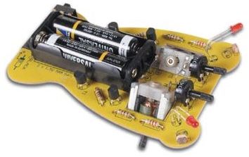 ROBOT-1 A simple robot can be made with 2 motors and two light-detecting circuits, (identical to the circuit above). The robot is attracted to light and when the light dependent resistor sees light, its resistance decreases. This turns on the BC547 and also the BC557. The shaft of the motor has a rubber foot that contacts the ground and moves the robot. The two pots adjust the sensitivity of the LDRs. This kit is available from Velleman as kit number MK127. |
|
SWITCH DEBOUNCER and PULSE PRODUCER Thus is one of the simplest and cleverest circuits ever produced (by Ron: http://www.zen22142.zen.co.uk/ronj/tg1.html Ron says: It produces a complete pulse every time the button is pressed. When the button is pressed, the output goes low for 3uS and produces a pulse to activate the clock-line of a chip. Our circuit produced 100% reliability and the cap takes 0.1sec to discharge. The circuit does not have any filtering to prevent switch noise as it relying on the fact that a single pulse is produced in 3uS and the circuit assumes no switch noise can be produced in that time-interval.  |
|
|

All the resistor colours:
 |
 |
 |
 |
 |
 |
 |
 |
| adv update 24-1-2014 |

|


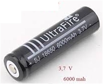

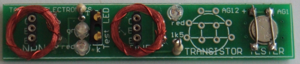
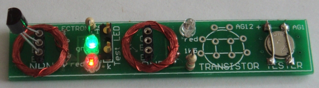
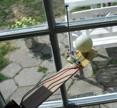


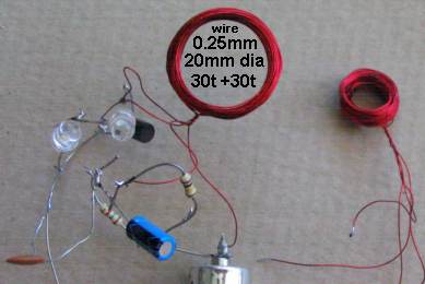
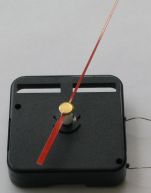 Voltage must be applied to the electromagnet around the correct
way so that repulsion occurs. Since the rotor is sitting equally
between the North poles, for example, it will see a strong
pushing force from the pole near the electromagnet and this is
how the motor direction is determined. A reversal of voltage
will revolve the rotor in the same direction as before. The design
of the motor is much more complex than you think!!
Voltage must be applied to the electromagnet around the correct
way so that repulsion occurs. Since the rotor is sitting equally
between the North poles, for example, it will see a strong
pushing force from the pole near the electromagnet and this is
how the motor direction is determined. A reversal of voltage
will revolve the rotor in the same direction as before. The design
of the motor is much more complex than you think!!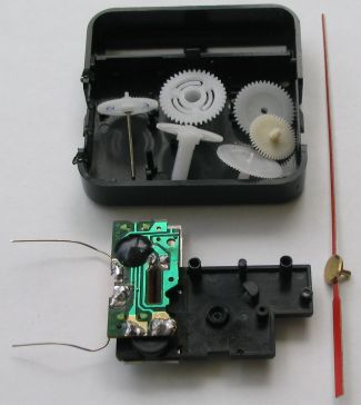
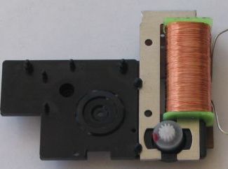
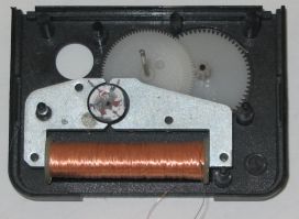
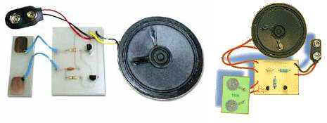
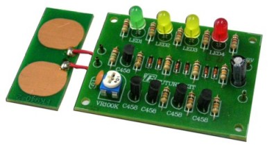
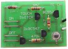

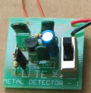
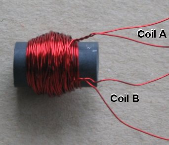
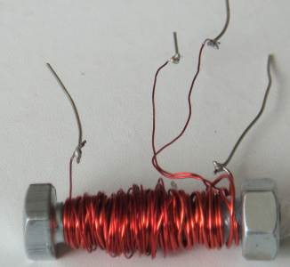
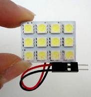
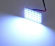
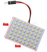
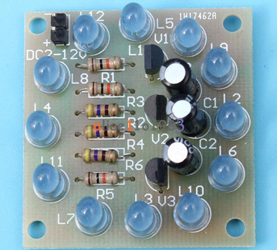
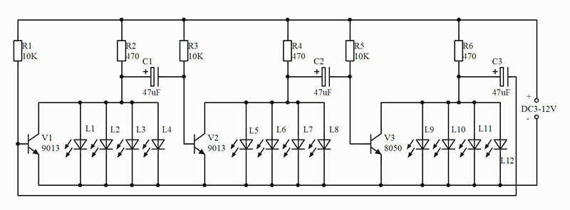
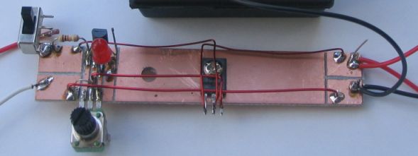 This power supply can be built in less than an hour on a
piece of copper-laminate. The board acts as a heat-sink and the other
components can be mounted as shown in the photo, by cutting strips to
suit their placement.
This power supply can be built in less than an hour on a
piece of copper-laminate. The board acts as a heat-sink and the other
components can be mounted as shown in the photo, by cutting strips to
suit their placement.