|
Buzz |
|
|
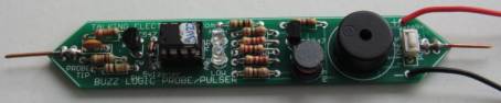
This project is an Audible Logic Probe with lots of extra features.
It uses an 8-pin micro to do all the work and the result is a handy piece of test gear with the main feature of detecting a HIGH, LOW or PULSE as well as being able to deliver a clock signal to activate "counting" chips.
It also has a number of alarm sounds to help you design an alarm amplifier.
Simply by injecting the signal into the front-end of an amplifier, you will be able to get an idea of the output from the horn speaker.
Everyone avoids buying test equipment.
But you cannot DESIGN, FIX or TEST anything if you don't have the right tools. A multimeter only gets you some of the way.
When a problem becomes more involved than just testing voltages, you need equipment designed for the job.
And a Logic Probe has a special feature. It will detect when a pulse has occurred on a line.
A multimeter is not quick enough to pick up a pulse and a digital meter is EXTREMELY SLOW and will never detect a pulse.
Without a Logic Probe you will never be able to diagnose some of the simplest digital circuits.
Talking Electronics has designed a number of different Logic Probes, and although they all detect a HIGH, LOW and PULSE, some also detect the ACTIVITY on the line by listening to the signal and reproducing it in a piezo.
This allows you to detect the different frequencies and determine if all the DIVISIONS of a chip are being passed to different parts of a circuit.
This project also has one other hidden feature.
It will beep after about 2 minutes if left connected to a circuit without being used. This prevent you flattening a project that is connected to a battery.
But this project is more than just constructing a Logic Probe.
It is part of a PIC MICROCONTROLLER COURSE to teach programming.
But it teaches you in REVERSE to any other course.
We show you complete projects with well-documented instructions, laid out in a simple TEXT FILE that you can modify and change to see exactly what each instruction does.
By simply increasing or decreasing different values, you will see or hear the changes and this is how you learn.
It is much easier and faster than any other way.
|
INSTRUCTIONS |
THE CIRCUIT
The circuit is very clever because a microcontroller does not liek an open input line and this is basically what is needed with a Logic Probe.
The tip of a probe needs to exhibit a very high impedance so it doe not have any effect on a line and if the line is HIGH, the red LED is illuminated. If the line is LOW the green LED is illuminated.
You cannot do this with the input of a microcontroller.
But we have done this with an INTERFACE CIRCUIT made up of a transistor and components.
The transistor does 2 things.
It increases the input impedance by being an EMITTER FOLLOWER because we have a 33k resistor discharging the 47p capacitor.
The program is a loop and it works like this:
GP4 goes HIGH and takes the base HIGH.
This will make GP3 HIGH, but the program does not recognise a HIGH.
If the input is take LOW, GP3 will be LOW and the program recognises the LOW.
The program then makes GP4 LOW and this will make GP3 LOW. The program does not recognise this state.
If the probe tip is taken HIGH, GP3 will be HIGH and the program recognises the HIGH.
The transistor prevents high voltages on the tip damaging the microcontroller.

It is "up-side-down"
because the positive of the micro is pin 1
and this pin is at the bottom of the chip.
THE PROGRAM
The program
consists of a number of sub-routines and a MAIN.
MAIN is always
This is where the micro spends most of its time.
It is executing a loop (or set of loops) and when an input changes, the condition of GP3 changes from HIGH to LOW or LOW to HIGH. This is what the program is "looking for" and the micro goes one of the sub-routines to carry out a particular task, such produce a beep or go to the tones section.
GP3 is the only input pin in this project.
It is affected (or changed or altered) by three different things:
1. It "sees" a HIGH when the probe is connected to a voltage above 3v.
2. It "sees" a HIGH when GP4 is HIGH and the probe is not connected.
3. It "sees" a HIGH when the switch is pressed.
A Logic Probe normally has the probe at a level mid-way between a HIGH and LOW. This allows the circuit to detect a HIGH or LOW.
But the input of a micro cannot be held "at a mid position." It must be either HIGH or LOW.
Thus we have a problem.
To solve the problem by making the tip HIGH then LOW via a sub-routine.
When we make it HIGH, and the sub-routine detects a HIGH, the result is ignored.
Bt if it detects a LOW, the result is a LOW.
When we make it LOW, and the sub-routine detects a LOW, the result is ignored.
But if it detects a HIGH, the result is a HIGH.
All the trickery is done in the program.
It shows how a theoretically impossible result can be produced with a few lines of code.
Click for larger image
All you have to understand is the fact that the micro is looping in Main
and goes to a sub-routine.
The tones are quite complex and creating a tone is very time-consuming.
All tones consist of turning an output pin ON and OFF and all tones
start by turn an output ON , creating a delay then turning it OFF. When
this is looped, a tone is created.
By increasing or decreasing the ON and OFF times, a different tone is
produced.
By experimentation, the correct tone will be produced.
If you loop this 10 times, then change the values, an increasing or
decreasing sound is produced. If you loop it 15 or 20 times, the rise or
fall is slower.
This is all very easy to understand, but creating the program is quite
complex because you need to create loops for each requirement.
In most cases these loops are inside a loop called an outer loop and
another loop may be inside these loops.
This is called NESTED LOOPS.
Learning how to create the loops and keep track of their execution is an
advanced skill.
To keep things simple, you just need to copy and past the sub-routine
provided (in this project) to the project you are developing. It may be
called Hee Haw or Siren and it can be used in anything you
are developing.
Finally, we have a reminder beep that beeps after 1 minute if the Logic
Probe is not used.
This is handy for those times when you are testing a battery operated
project and don't want to waste the battery.
You can use any of the sub-routines in another project.
FILES
Here are the files for the project:
Do_It_NOW.asm
Do_It_NOW.txt
Do_It_NOW.hex
CONSTRUCTION
A kit of components is available from
Talking Electronics.
All the components are included in the
kit
and everything is identified on the board.

PARTS
LIST |
|
1 - 47R resistor 3 - 100R resistors 2 - 220R resistors 1 - 2k2 resistor 1 - 10k resistor 1 - 33k resistor 1 - 100k resistor 1 - 47p ceramic 1 - 3mm red LEDs 1 - 3mm green LED 1 - 5v1 zener diode 400mW 2 - BC 547 transistor 1 - 16mm piezo diaphragm (12 to 22mm) 1 - 10mH inductor 1 - PIC12F629 (with Buzz) 1 - 8 pin IC socket 1 - mini tactile switch 1 - 20cm red hook-up flex 1 - 20cm black hook-up flex 1 - square ezi clip - red 1 - square ezi clip - black (or green) 2 - metal probe tips 1 - 5cm tinned copper wire 0.5mm 20cm very fine solder 1 - Buzz Logic Probe PCB |
TEST EQUIPMENT
Talking Electronics has a number of pieces of TEST EQUIPMENT to help in the design and testing of projects.
Of course you can use a multimeter for most of the testing but some of the "tricky" faults need a special piece of equipment.
You may only need a LOGIC PROBE once a month, but the project you are designing will come to a stand-still if you can't locate a problem.
We designed all these projects because we needed them ourselves.
Add one of them to each order you place with Talking Electronics and eventually you will have the whole range.
|
LED TESTER Tests LEDs. $1.50 plus $4.00 post (buy a number of kits and pay only one postage) |
 |
|
CONTINUITY TESTER Only responds to resistance less than 50 ohms. Ideal for digital projects as it tests connections very quickly. $12.50 plus $6.50 post (buy a number of kits and pay only one postage) |
 |
|
LOGIC PROBE with PULSER
- slimline Detects HIGH and LOW signals on both TTL and CMOS circuits. The piezo allows you to hear low frequency signals and the signal injector (Pulser) will over-ride clock signals to make a circuit operate at a reduced frequency. $8.00 plus $6.50 post |
 |
|
SUPER PROBE 20 different functions. See article for the complete list of functions. $18.00 plus $6.50 post |
 |
|
COMBO-2
TRANSISTOR TESTER Tests transistors and shows the gain of the transistor. Also has Signal Injector probe. $21.50 plus $6.50 post |
 |
|
Simple
Transistor and LED Tester - 3 Tests PNP and NPN transistors and LEDs. Also teaches the amazing property of an air-cored coil in producing a high fly-back voltage. $4.00 plus $3.00 postage. (buy a number of kits and pay only one postage) |
 |
|
MAINS TRACER Detects 240v AC mains hidden in walls etc. Will also pick up RF signals from a keyboard to show you where Electromagnetic Radiation is coming from and giving you a headache. $10.00 plus $4.50 post |
 |
|
CABLE TRACER
- 100MHz Traces cables when the power is OFF. Uses an FM radio to pickup beeps. $10.00 plus $4.50 postage.
(buy a number of kits and pay |
 |
|
OP-AMP TRAINER and TESTER Teaches how an op-amp works by using pots to control the voltages on the two inputs. $24.50 plus $6.50 post (comes with instructions) |
 |
|
PIC Fx-1 MICRO (8 pin) PROGRAM DEVELOPER and TESTER Learn to program PIC chips. Comes with a pre-programmed PIC12F629 chip with 3 routines. $12.00 plus $6.50 post |
 |
|
model railway
POINT MOTOR CONTROLLER and TESTER
CDU-Inline The cheapest CDU project you can get. $8.50 plus $6.50 post |
 |