|
|
|
|

Why spend $2 on a
"Whistle Key Finder" when you can spend $10.00 on producing your own
design?
Why?
Because you don't learn anything when you buy the $2.00 device.
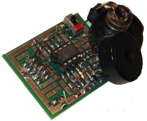
The piezo has been moved slightly to show the surface-mount components.
The 5 pins on the left are for In-Circuit Programming.
The coin holder positive has been bent to hold 3 button cells
The LED on the lower corner was used to test the chip.
This project uses one of the smallest chips in the
PIC microcontroller range, the PIC12F629 and you can learn to program it
and experience the thrill of making something yourself and see what goes
into writing a program.
Even a program as simple as this one is not easy to put together and if
you are starting from scratch, you will need a programmer (a "burner")
and all the data that goes with "burning" and creating a program for the
micro.
We use the PICkit-2 as it is the cheapest and best. It comes with USB
cable and 2 CD's containing the programs needed to "burn" the chip. You
will also need NotePad2 to write your .asm program
(use
Whistle.asm or
Whistle.txt as a template for your
program).
The PC board includes 5 pins for "In Circuit Programming" via PICkit-2 and
you will be encouraged to use surface-mount components to interface the
piezo diaphragm to the chip.
One of the clever parts of the circuit is the piezo is used to detect
the sound and then produce the beep-beep-beep reply.
Be reminded that not all piezo diaphragms are the same. Some are very
sensitive when detecting audio and others are not sensitive at all.
Ours produces an output of about 20mV to 50mV when whistling up-close, while an insensitive
diaphragm will produce only a few millivolts.
The CIRCUIT
The circuit consists of two
common-emitter stages with enough gain to produce a rail-to-rail signal
when the piezo detects a whistle.
We are not concerned about distortion or over-driving the chip as we want a
fairly square wave.
A super-alpha arrangement was tried using two transistors but it did not
work at all.
It is surprising how "theory" does not always work in practice and
that's why you must try everything before settling on a result. Each
stage has a gain of approx 70, making the total approx 5,000. This
allows a 1mV signal from the piezo to produce a rail-to-rail waveform.
As we mentioned, the interesting feature of the circuit is the use of the piezo to detect
a signal and then produce a beep.
This has been done by making the piezo "float."
It is not connected to any rail and although it is connected to pins of
the chip, these can be made "inputs" and thus become high
impedance.
The 4k7 on the base of the transistor allows the piezo to be driven by
the chip in "bridge-mode" where the pins are alternately made high then
low so that twice the supply voltage is effectively delivered across the
piezo to increase its output.
Without the 4k7, the lead of the piezo would not rise above 0.6v due to
the base-emitter voltage limitation.
When the piezo is required to detect a signal, one lead is connected to
0v via a pin of the chip and the other lead connects to the base via the
4k7. The pin on the chip is changed to "input" during this
operation.
When the piezo is activated, the signal is also amplified through the
transistors but the chip is not in detection-mode and this signal is not
detected.
SURFACE-MOUNT COMPONENTS
To keep in line with
miniaturisation, we have used surface-mount components. Once you start
using surface-mount components, you get hooked. Through-hole components
seem enormous. You will need fine tweezers to hold them in place while
one end is soldered.
Always use very fine solder as you only need very little for each
component and the main reason for adding extra is to take advantage of
the flux to clean the connection. Always solder resistors with the value
showing. Capacitors don't have values marked on them and you cannot work
out the value by the size of the component.
That's why you have to know the value before taking them out of their
"carrier."
CONSTRUCTION
You can build the circuit on any
type of PC board and we have used a small prototype board that needs
some of the tracks cut to suit the placement of the 8 pin IC socket.
The kit of components comes with all the parts you need to get the
project working, including a pre-programmed chip and a prototype PC
board that needs some tracks cut.
We will not describe any construction details as most constructors will
be adept in placing components. The only thing to remember is to cut the
tracks before fitting the IC socket as some tracks run under the socket.
To modify the program you will need a PICkit-2 programmer and this comes
with 2 CD's containing all the software needed for In-Circuit
Programming.
You will also need a lead to connect the programmer to your lap top via
the USB port (comes with PICkit-2) and an adapter we call a 6pin to 5 pin
Adapter to connect
the PICkit-2 to your project. (The photo below shows the prototype 6pin to 5
pin Adapter. A PC board is now available for the adapter.)
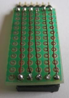
PICkit-2 and Adapter connected for In-Circuit Programming
The
PROGRAM
The program detects
the signal from the diaphragm and only processes a waveform that falls in
the 2kHz region. A 2kHz signal has a period of 1,000,000 / 2,000 =
500uS. The period of a waveform is the time taken to travel from the 0v
level to the maximum (positive), then to the max negative and back to
the 0v level. Of course this time is also the distance between two peaks
but it is more convenient to describe it in our terms (starting at the
0v level).
This means the time when the signal will be HIGH will be 250uS and 250uS
for a LOW.
If we take the HIGH portion, we can "open the gate of the chip" by
making a pin INPUT and looking at that pin to see if it is HIGH. The
signal will create a HIGH on the pin.
We create a very short-duration loop to look for a HIGH and when it is
detected, we delay nearly 250uS and see if it is still HIGH.
A short time after this, the signal should be LOW and if this is the
case, we look for a LOW of about 250us and see if the signal becomes
HIGH just after 250uS.
This is the principle of looking for a 2kHz signal and we have
allowed for a "look" just slightly before and after 250uS to cater for
frequencies just slightly above and below 2kHz. Each time the micro
detects a high and low, it increments a file called "count."
Now, there's what is also happening:
We are only looking for a signal for about 100mS (100,000uS) and this
"time-delay" is
done in the background via a set of registers that are incremented by
the clock in the PIC chip.
When the registers fill and roll over, the micro leaves the section it is executing and goes to a sub-routine called "isr."
This is the Interrupt Service Routine and it tells the micro to
go to Main2 where the number of cycles stored in the "count" file
is
released as beeps from the piezo.
But first, only values in the high nibble in the "count" file are used.
The nibbles are swapped so that the value in the upper 4 bits will be
used. The register is then shifted two places to the right so that the
two top bits appear in the lowest places in the register. The register
is then masked to get only the two
lowest bits. This produces 1, 2, 3 or 4 beeps.
Finally, the program has a delay in the "isr" that makes the micro beep
3 times after approx
1-minute of non-detection.
The most difficult part of the program is detecting a narrow band of
frequency. We have done this in the section "aa" to "dd" but it can be
improved and it is your job to narrow this filter and only detect a
whistle.
The micro loops around the instructions contained at "aa," "bb,"
"cc," "dd" and when the 131,072uS has been reached, the micro goes
to address 4 where it finds the instruction to go to isr. This is how it
gets out of the loop.
Another important feature of this program
is the coverage of the INTERRUPT routine.
To enable the micro to count in the background then go to the interrupt
location (address 4), requires a number of bits to be set in a number of
files. The setting of these bits in the various files is shown in
"Main."
When you are creating another project that requires similar "counting in
the background," you will be able to "cut and paste" the
code.
(Point to remember:
Timer0 does not produce a long delay, so Timer1 has to be used).
Here are the files you will need:
Whistle.asm
Whistle.txt
Whistle.hex
;Whistle (Key Finder) 12F629.asm ; 9-7-2009 list p=12f629 radix dec include "p12f629.inc" errorlevel -302 ; Don't complain about BANK 1 ; Registers during assembly __CONFIG _MCLRE_OFF & _CP_OFF & _WDT_OFF & _INTRC_OSC_NOCLKOUT ;Internal osc. ;Files for 12F629 start at 20h temp1 equ 20h temp2 equ 21h count equ 22h beep equ 23h timer equ 24h ;beeps after 1 minute to let you know it's on ; globals GPIO equ 05h status equ 03h option_reg equ 81h TRISIO equ 85h ; bits pin7 equ 0 ;GP0 pin6 equ 1 ;GP1 pin5 equ 2 ;GP2 and T0CkI pin4 equ 3 ;GP3 input only pin3 equ 4 ;GP4 pin2 equ 5 ;GP5 z equ 2 ;zero flag ;bits rp0 equ 5 ;bit 5 of the status register Start org 0x00 ;program starts at location 000 goto SetUp nop nop ;NOPs to get past reset vector address org 4 goto isr nop SetUp movlw 07h ;Set up W to turn off Comparator ports movwf CMCON ;must be placed in bank 0 goto Main ;Main ;Delays _25uS movlw .7 movwf temp1 decfsz temp1,1 goto $-1 retlw 00 _130uS movlw .45 movwf temp1 decfsz temp1,1 goto $-1 retlw 00 _250uS movlw .84 movwf temp1 decfsz temp1,1 goto $-1 retlw 00 _100mS movlw .100 movwf temp2 nop decfsz temp1,1 goto $-2 decfsz temp2,1 goto $-4 retlw 00 _250mS movlw 0FFh movwf temp2 nop decfsz temp1,1 goto $-2 decfsz temp2,1 goto $-4 retlw 00 ;interrupt service routine isr nop decfsz timer,1 ;creates 1 min delay to let you know it is on. goto Main1 movlw 03 movwf count goto sss Main bsf status,rp0 ;Bank 1 movlw b'00100100' ;Set GP2 input GP5 input movwf TRISIO movlw b'10010100' movwf OPTION_REG ; x000 0000 x=1= weak pull-ups disabled ; 0x00 0000 INTDEG Don't care ; 00x0 0000 x=0 = internal instruction clock ; 000x 0000 Count on falling edge - don't care ; 0000 x000 0=prescaler assigned to timer0 ; 0000 0xxx = 111 = 1:128 x100=1:32 bcf status,rp0 ;bank 0 bcf GPIO,4 call _100mS ;(settling time) movlw b'10100000' ;b'10100000' movwf INTCON ;,0 1=GP0,5 interrupt flag ;,1 1=GP2 interrupt occurred ;bcf INTCON,2 ;1=TMR0 overflowed. Clear overflow flag ;bcf INTCON,3 ;1=enable GPIO port change interrupt ;bcf INTCON,4 ;1=enable GP2 external interrupt ;bsf INTCON,5 ;1=enable TMR0 overflow (interrupt) ;bcf INTCON,6 ;1=enable all peripheral interrupts ;bsf INTCON,7 ;1=enable all unmasked interrupts bcf INTCON,5 ;0=disables TMR0 interrupt bsf INTCON,6 ;1=enable all peripheral interrupts movlw b'00010101' ;b'00110001' movwf T1CON ;,7 not used ;,6 0=Timer1 is ON ;,5,4 11=8 prescale (max) 01=1:2 ;,3 bit ignored ;,2 This MUST BE SET!!!!!! ;,1 0=int clock ;,0 1=enable timer bsf status,rp0 ;Bank 1 bsf PIE1,0 ;,0 1=enables TMR1 interrupt bcf status,rp0 ;bank 0 bcf PIR1,0 ;clear TMR1 overflow flag clrf TMR1L ;clear the Timer1 low register clrf TMR1H ;clear the Timer1 high register clrf count ;count the number of cycles ;Timer0 is not used ; will go to isr when overflow occurs in TMR1 ;0.13 sec when prescaler=1:2 131,072uS ;input is LOW when no audio detected. aa call _25uS btfss GPIO,2 ;Is input HIGH? Start with a HIGH goto aa bb call _250uS btfss GPIO,2 ;Is input LOW? goto cc goto aa ;freq too low cc call _250uS btfsc GPIO,2 ;Is input LOW? goto dd goto aa ;freq too low dd incf count,1 goto bb Main1 bcf PIE1,0 ;,0 0=disables TMR1 interrupt bcf T1CON,0 ;disable timer1 bsf status,rp0 ;Bank 1 bCf INTCON,7 ;disable all unmasked interrupts bcf INTCON,5 ;disables TMR0 interrupt bcf status,rp0 ;bank 0 swapf count,1 rrf count,1 ; rrf count,1 ;only use top 2 bits movlw b'00000011' andwf count,1 ;max 4 beeps movf count,1 btfsc status,z ;z flag will be SET if file is zero goto Main sss bsf status,rp0 ;Bank 1 movlw b'00000100' ;Set GP4,5 output movwf TRISIO bcf status,rp0 ;bank 0 call _250mS movlw 0FFh movwf beep bsf GPIO,4 bcf GPIO,5 call _130uS bcf GPIO,4 bsf GPIO,5 call _130uS decfsz beep,1 goto $-7 decfsz count,1 goto $-12 call _250mS call _250mS call _250mS call _250mS goto Main end |
GOING
FURTHER
We have not produced the
"Ultimate Key Finder" project. We have left some improvements for you to
work on.
The detection software could be improved, the beep could be changed and
the 1-minute alert could be lengthened.
These are all things for you to try.
I don't think you will be able to turn the project into voice recognition but you
will certainly be able to produce different tones or even a set of notes
to indicate when a whistle is detected.
It's now up to you.
|
|
|
18/6/09