LOTTO
NUMBER SELECTOR
USE OUR LOTTO SELECTOR TO WIN A FORTUNE!
LOTTO or POOLS selector - to help you win a fortune!
Single or Dual dice for games such as Monopoly.
Percentile Dice for war games or other strategy games.
As a random number generator for pure amusement.

|
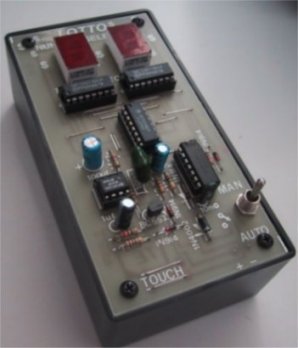
The completed Lotto Selector |

|
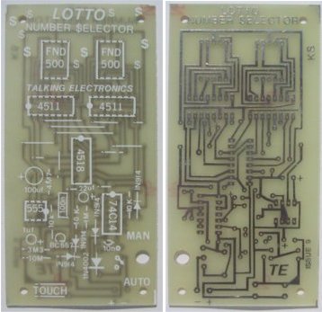
The complete LOTTO circuit. The schematic diagram closely follows the layout on the PC board. |
This project is a real winner in more ways than one. When you understand how the circuit works, it is really 4 projects in one. And it has two modes of operation: MANUAL and AUTOMATIC.
Everyone likes a little flutter. The introduction of so many outlets in competition for the gambling dollar is positive proof of this. Every week the total prize pool for these games rises and this alone must draw in many new customers.
The possibility of winning something for nothing lures even the most cautious person into buying a ticket. Nothing has been more successful than LOTTO. The concept of choosing your own numbers is brilliant. It has fooled the greater percentage of punters into thinking they are closer to picking a winner by this method, than buying a pre-numbered ticket. Although nothing could be further from the truth, no amount of explanation will deter the avid investor from his weekly punt. So, rather than being against them, we have decided to join forces and produce our contribution to selecting a winning combination. . . we have called our electronic number predictor: LOTTO NUMBER SELECTOR.
It will almost certainly create a fortune for someone and provide lots of fun in construction and operation.
Our circuit is a real gem. It looks simple but lurking within the 5 chips are a number of interesting building blocks.
The most significant feature of the circuit is the absence of 14 display resistors. Both the 4511's are display drivers and under normal conditions, a set of dropper resistors would be required. We have designed our circuit with only 1 for each display.
At the other end of the electronics ladder we have used a single-pole switch with a centre off to provide 2 functions.
To achieve this we have had to insert the switch in the negative line. All these features are fully explained in the text.
THE EFFECT
When the power switch is turned on (to either MANUAL or AUTOMATIC), the two displays will show two figure '8's'. These will gradually show down to a flicker and numbers will start to flick onto the displays. This will slow-down even further until double numbers can be identified. Finally, a random number will remain on the screen.
A BRIEF SUMMARY OF HOW THE CIRCUIT WORKS
When the power is turned on, a Schmitt Trigger oscillator supplies a 10kHz signal to a 4518 chip. This is a divide-by-ten counter with 2 separate stages. The output of these is in binary and these 4 lines of binary are fed to individual display drivers.
The numbers appearing on the two displays are randomly generated due to another slow cycling oscillator providing the halt condition. Between each number appearing on the screen, the high speed oscillator is generating up to 40 clock counts.
TWO-UP!
Take a simple penny (we will have to convert to a 20¢ coin for the younger readers however a penny has much more feeling and authenticity when it comes to gambling). A penny was used anywhere from a cricket field to the bar in a hotel for decision making. It provided answers to complex questions such as "who will shout next', "who bats first" or "who pays the taxi fare".
The chance of a coin landing heads is 50%. Thus it is obvious to everyone as being a fair way of solving a dispute.
A die or dice is also used in decision making and the chance of scoring a high number is one-in-six.
These are easy figures, However if I asked about the probability of selecting 6 numbers from a total of 40, most people would give an answer which would be so far from reality that they would be astonished.
Very few people understand high numbers. As proof, try a friend with this simple problem. Take a sheet of paper and tear it in half. Place the two halves on top of each other and tear the stack again. Repeat the operation 20 times. How high do you think the pile of paper will be? If I said it would reach the moon, would you be impressed? Such is the enormity of multiplication.
Because it seems so utterly impossible to create an enormous possibility with just 40 insignificant numbers, LOTTO has taken off from its very inception, and never looked back. Chance and probability is a fascinating mathematical study. One which can engross a dedicated mathematics student for his entire life.
The pseudo study of probability has been the downfall of many a punter as everyone thinks he or she is a good predictor.
Without the correct mathematical data, the casual backing of 'hunches' or 'certs' will eventually bring the novice to bankruptcy.
It is only by using probability correctly that you will increase your winnings. However the gain rate is only 2 to 5 per cent and few people are happy with low margins. They want big wins and quickly!
Don't think I am encouraging this form of wager. Just because I have presented a Lotto Selector does not indicate my acceptance of gambling of any kind. And yet by stating that, I am a hypocrite. Life is a gamble. Running a business is a gamble. Even driving to work or buying a product is a gamble.
Gambling itself is not a danger. It is only the excess of gambling which leads to ruin.
So, away from the preaching.
If you are against any form of gambling, you can use the LOTTO project to play a number of harmless games.
The two readouts can be considered a dual die, in which the numbers 1 to 6 are used, and any other numbers are ignored.
Other games such as war games or MONOPOLY require percentile readout and both digits can be used.
On the other hand you can use it on a personal basis to guess the next number to appear. With the switch set to the automatic position, you can use the project as a guessing game.
This is even more dramatic in a darkened room where the display will give the best results. You can even use it as a sleep inducer and try to stay awake until the batteries run down!
HOW THE CIRCUIT WORKS
THE SCHMITT OSCILLATOR
The heart of the LOTTO SELECTOR is a free-running oscillator. This is made up of a Schmitt Trigger between pins 13 and 12 of the 74C14. It oscillates at approximately 10kHz due to the value of the frequency-setting components: the 10n capacitor and 4k7 resistor.
The output of the oscillator has a very short duty cycle due to the presence of the 1N4148 diode. This means the ON time for the output is very short compared with the OFF time. The charging time for the 10n capacitor is provided by the diode and because it has a very small voltage drop, the capacitor is charged very quickly.
When the capacitor charges to 2/3 of the rail voltage, the trigger changes state and the output goes LOW. The diode is not reverse-biased and does not have any effect on the discharge of the capacitor. The discharge time is provided by the 4k7 resistor. These two components are the frequency-setting items. The discharge-time to charge-time is approximately 25:1. This duty cycle will not affect the counting of the decade counter chip (4518) but is an essential part of a very clever design. More on this later.
The 10kHz signal is passed to the clock pin of one half of the 4518. This chip is a decade counter and will divide the incoming pulses by 10. It is designed to give a readout of the numbers 0 to 10 in binary form and this requires 4 output lines as shown in the diagram.
The highest priority line (pin 14) is then taken to the clock input of the second stage. The result is a counter capable of counting to 100.
Each of the outputs consists of 4 lines of binary information of a decimal number. Thus it is called BINARY CODED DECIMAL.
These outputs are passed to a 4511 display driver chip which is designed to convert the binary information to 7 lines of information to drive a 7-segment display. One chip is fully employed doing this because of the number of pins required.
Another feature of the 4511 is the LATCH or FREEZE capability.
A number can be frozen on the display while another is being setup on the input lines.
Two pins control this effect.
One pin (pin 4) is called the BLANKING INPUT pin. It has the effect of turning off all the segments when it is LOW. This means it is ACTIVE LOW. (It produces an effect when it is LOW).
The other pin (pin 5) is the LATCH ENABLE pin. It produces the freeze effect when it is HIGH because it enables the latch (allows it to operate) when it is LOW. This is what happens: If pin 4 is LOW, you will not be able to see anything on the display at all. When it is HIGH, the figure on the display will depend on the values of the incoming BCD lines and also the state of the LATCH ENABLE pin number 5.
If pin 5 is LOW, the numbers will change on the display according to the change in the incoming information. When it is HIGH, the display will freeze and the incoming information will not get through the latch circuit.
Now imagine the blanking pin being turned on for 4% of a cycle and off for 96%. This is occurring at 10,000 times a second, when the LOTTO project is switched on. Because the speed of this flashing is too fast for us to see, we think the display is on all the time. But electronics is faster than the eye. The display (made up of 7 light emitting diodes) will respond to this speed and they will turn on and off without being damaged.
The reason for this clever circuit arrangement is very interesting. You will notice we have included only 1 dropping resistors between the display and the driver chip. Normally we would require 7 resistors of about 470 ohm for voltage dropping to each display. And this circuit would need 14 resistors. We have used only two. How clever! This has saved parts, space and layout problems. The reason for choosing this method of operation is two-fold. We avoid the wasted power produced by large-vale droppers and secondly, the display is allowed to operate at a more efficient level.
To achieve a good level of brightness, it is possible to drive the displays with 4 times the normal current for a very short period of time. This produces a bright display because the light emitting crystals have a higher efficiency at higher currents.
The next feature to look at is the number changing circuit.
This is accomplished by briefly bringing pin 5 LOW, then HIGH again. The new number appearing on the BCD lines will be frozen by the latches and displayed on the displays. A 555 is used for the number-changing operation because it can be designed in a circuit to have a very short pulse width, can be made to slow-down and is guaranteed to go LOW at the completion of its cycle.
The slow-down operation is accomplished by a BC557 transistor. This transistor is being turned on by the charge (voltage) on a 1u electrolytic and the transistor is acting as a variable resistor. The transistor and 10k make up the charging resistance for the 100n capacitor. The discharging resistor has been eliminated and this means the LOW time for the cycle will be very short.
|
Lotto Selector Block Diagram |
To start the slow-down oscillator functioning, the 1u electrolytic is charged slightly when you place your finger on the TOUCH WIRES. This voltage is passed to the base of the BC 557 transistors via the 10M resistor and a 'turn-on' condition occurs between base and emitter. The 3M3 resistor is a bleed resistor to slowly discharge the 1u electrolytic. This causes the 'effective resistance' between the emitter and collector to change and the 555 responds by changing its clock rate. The 4M7 across the 100n timing capacitor ensures the voltage on the 100n decays to zero and prevents the 555 from giving out random clock pulses once it has stopped.
The circuit is designed for AUTO or MANUAL operation.
In the manual position, the touch switch comes into operation and you can throw your own numbers by touching the TOUCH SWITCH.
In the AUTOMATIC position, The LOTTO SELECTOR will dial up a number, display it for a few seconds, then start counting again. This automatic control is governed by a long time delay created by the Schmitt Trigger between pins 5 and 6. Its repetition rate is controlled by the 1M resistor and 22u electrolytic. Normally the output of the trigger inverter is HIGH. This causes the 22u electrolytic to charge up via the 1M resistor to 2/3 rail voltage. The trigger circuit changes state and the output goes LOW. When this happens, the 1u electrolytic in the slow-down circuit is charging up via the diode and this has the same effect as touching the TOUCH WIRES.
The 22u electrolytic discharges via the 1N 4148 diode (and the 10k resistor) fairly quickly and this gives a brief pulse on the 1u electrolytic. When the voltage on the 22u electrolytic falls to 1/3 of the rail voltage, the output of the trigger inverter goes HIGH. The slow-down circuit comes into operation to give you a new number. This repeats itself ad infinitum.
Lastly a clever trick with the on-off switch.
So that the long delay timer does not come into operation when the Selector is set to Manual, we have held the voltage on pins LOW via a diode. It may not be easy to see, but the 1N 4002 is positioned so that it supplies the rest of the circuit with power when switched to the MANUAL position. In this setting, the 1N4148 diode is connected to earth and pin 5 cannot rise more than .5v, thus the trigger circuit will not cycle. This arrangement could not be done in the positive line as the Schmitt trigger must be held LOW for its output to remain HIGH.
ASSEMBLY
All the components fit on the top side of the printed circuit board and each
part is identified on the overlay. Your task is to learn about identifying the
parts while constructing the project. So take your time.
Lay the components on the work-bench and make sure all the parts are present by
referring to the parts list. Place the resistors around one way and grade them
into ascending order. Don't make a mistake between the 1M and 10M. Check the
difference between blue and green.
The first items to fit onto the board are the jumper links. These are made from
tinned copper wire which has be straightened to remove any kinks. Start at one
end of the board. Cut a length of wire and bend it into the form of a staple or
'U' shape. Fit it through the holes in the board and solder each end with a hot
soldering iron. When soldering is completed, the jumper link should be touching
the board and the wire should be straight. Complete the 12 links and two TOUCH
WIRES with the same type of tinned copper wire.
Next components to mount are the diodes. These are sometimes hard to identify
and an important point to note is the COLOUR of the band is NOT the
major identification. It is either the thickness of one of the end bands or its
position at the end of the diode.
Take these examples:
A diode with a blue painted band indicates the
cathode. Do not take any notice of the red lead inside the glass bead. This is
purely the colour of the terminating cup for the crystal.
A diode with these bands: a thin brown line, a thin yellow
line, a thin red line and a thick yellow line. This is identified by the thick yellow
line being the cathode.
The 8 resistors are the next components to fit
onto board. The leads should be bent close to the end of the resistor but not
so sharply that the lead is likely to break off. Insert the resistor until it
touches the PC board. You should be able to hold your fingers on the resistor
while you tack one end with the soldering iron. The other end can then be
soldered and the first end re-soldered to create a perfect connection.
Double-check the value of each resistor before
going on to the next to make sure a mistake has not been made.
|
The Lotto Selector Printed Circuit Board |
Fit the 5 IC sockets so that the pin 1
identification on the sockets covers the dot on the PC board. This will make it
easier to insert the chips around the correct way at the completion of the
project. Solder each pin cleanly and swiftly, making sure the lands do not
bridge with solder.
The two FND 500 displays are identified by the
decimal point and these are soldered in position as shown in the photograph.
The 1N4002 power diode is mounted so that the
line on the diode case corresponds to the cathode lead on the overlay.
The 3 electrolytics are fitted so that the
positive lead (the longest lead) fits down the marked hole. Take care when
doing this because the marked lead on the case of the electrolytic is the
negative lead.
The two greencap capacitors can be fitted
around either way and are soldered in position so that they touch the board.
The BC 557 transistor fits directly into the 3
holes on the PC board.
Connect the ON-OFF-ON power switch through the
hole in the PC board and use tinned copper wire to connect the 3 leads to the
board. A battery snap finishes the construction of the project.
All that is left to do is fit the 5 chips into
their sockets with pin 1 covering the dot on the PC board.
The LOTTO SELECTOR is now ready for run-up.
A 9v transistor battery or 6 AA cells in a
holder is recommended for the first trial run. Nicads can deliver a very high
current and may cause damage if a short circuit is present.
After the selector is found to be working
properly, a set of nicads can be used as the power source.
|
The Lotto Selector fits onto a Project Box |
EXPERIMENTING
WITH THE LOTTO SELECTOR
A number of features of the LOTTO
SELECTOR can be examined with the aid of a LOGIC DESIGNER. This handy piece of
equipment will be covered in a future issue and is really an essential addition
to your workshop.
Here is a run-down of its capabilities.
It is basically a digital man's CR0. It will let you know when a digital
circuit is working correctly and will be much more use than a multimeter.
In some instances it will be more informative than a CR0 since it will tell you
when the amplitude of a pulse is sufficient to drive the input of a counter.
The LOGIC DESIGNER also has a division stage so that frequencies up to about
5kHz can be counted directly. A one-shot circuit produces individual pulses so
you can slow down the operation of a circuit so that it can be understood. The
Logic Designer lets you "see" into the workings of a circuit.
Here is how to connect the Logic Designer to the LOTTO project:
Set the Logic Designer to 9v, and supply the Lotto with a separate 9v, such as
a battery.
To test the Lotto project you will need a common line from the Logic Designer
and this is done by taking a jumper lead from the pin marked GND on the
Designer, near the bridge diodes, and connecting to the negative on the Lotto
at the centre of the switch.
Alternatively, the Lotto Selector can be connected directly to the Logic
Designer between the positive takeoff point (marked with a + at the top of the
PC board) and ground GND. A test lead can now be taken from any of the inputs
on the Logic Designer to the Lotto board.
The Logic Designer can be set to provides divide-by-1280 by connecting the 'C'
output of the 4026 to the clock input of the 4024 binary
counter. The clock input of the 4026 has a jumper lead attached and this
is used to probe the output of the high-frequency oscillator (74c14).
The 74c14 has been buffered so that you can read the output frequency. Do
not probe pins 12 or 13 as this will kill the oscillator and the displays will
light up like candles. Refer to the following diagram and probe pins 10, 9 or 8
to detect the presence of a high frequency waveform.
Place the probe lead on pins 11, 12, 13 and 14 of the 4518 and notice the
different frequencies of the BCD lines. An even higher division is available
from pins 3, 4, 5 and 6. By using pin 6 and the 1024 division of
the Logic Designer, you will be able to determine the frequency of the 74c14
oscillator.
Look at the binary counter outputs on the Logic Designer. The highest division
is labelled '64' and this indicated that it illuminates after a count of 64. It
remains on for 64 counts and thus a complete cycle for this LED is 128. We have
connected the Logic Designer to represent a division of 1280 by connecting the
decade divider (4026) to the input of the binary counter.
Further stages of division are provided by the chips on the Lotto Selector.
Each half of the 4518 is a divide-by-ten making the total division 128,000.
The high frequency oscillator will be running
at 10kHz to 14kHz and you will be able to see this frequency being divided down
to a point where you can actually count the cycles.
Attach a jumper lead to pin 6 and the 4518 and take this to the clock line of
the 4026. The 'C' output of the 4026 is taken to the clock of the 4024. The
count point is LED '64'. Start the timing operation when this LED comes on and
this is counted as zero. The next time it comes ON, it is counted as 1. Keep
counting until 10 and stop timing.
The frequency of the slow-down oscillator can
be detected on the Logic Designer by touching pin 3 of the 555 on the Lotto
board with the jumper lead.
When you touch the TOUCH SWITCH, the Logic
Designer display will tick over synchronously with the Lotto displays. The
binary counter will show exactly how fast the 555 is clocking.
The Lotto Selector can be modified to count to
40 instead of 0-99. This requires only a small amount of track cutting between
the 4518 and 4511 chips displaying the "tens" and the addition of a diode and
resistor to create a reset condition on the count of 40. The double zero is
read as 40.
The modified circuit is shown below:
|
Count - to - 40 Modifications |
IF IT DOESN'T WORK
If the LOTTO SELECTOR doesn’t work you will need a multimeter and the LOGIC
DESIGNER to get into the signal side of the circuit.
The illumination of the displays will be the
deciding factor on where to look.
IF THE DISPLAYS
DO NOT LIGHT UP
Connect the negative terminal of the battery to the project and use a jumper
lead connected to the positive terminal as a test lead. Place a 1k resistor
in line with this test lead and switch the project on to MAN or AUTO. The Lotto
project will not be powered by the battery for this test and, in fact the
circuit must not be operating for this part of the test as the outputs of the
4511 will short out our test-voltage.
Touch the 1k resistor along the top row of pins
for each of the 4511's (pins 9 to 16 and you will see each segment of the
display light up in turn. If they do not light up, either the displays are
faulty or the common earth lead is not connected to ground. You can also try
these pins when the 4511's are removed. If the displays only light up when the
chips are removed, the 4511's may be faulty or damaged.
If the displays check out ok with the 1k test resistor, but still fail to
light, the fault may come from the BLANKING line. This is pin 4 of the 4511's.
If this line is held LOW, the displays will not light.
You must be very careful when checking pin 4.
You cannot let pin 4 float nor can you put a HIGH on pin 4 because the displays
are directly coupled to the driver chips and may burn out if full rail voltage
is applied to them. Pin 4 is normally receiving a very short pulse and only
this short duty cycle can be duplicated for the correct operation of the set. A
CR0 will show you the mark-space ratio of the incoming pulse but in the absence
of this piece of test gear, you can use the Logic Designer as previously described.
A failure of the Schmitt trigger oscillator
between pins 13 and 12 of the 74c14 will cause the displays to remain unlit if
pin 12 is LOW or if pin 13 is HIGH. Pin 13 may be touching pin 14 or receiving
a leakage from the 9v rail. The 10k resistor may be faulty and failing to
discharge the 10n capacitor. The Schmitt inverter may be damaged. If this is
the case, you can use one of the unused inverters in the package.
IF THE DISPLAY
LIGHTS UP LIKE A CANDLE
If the displays light up far too brightly, the fault lies in the high frequency
oscillator between pins 13 and 12 of the 74c14. Turn the Lotto Selector off
immediately and add a 100 ohm resistor in one line of the battery. You can now
trace through and find the fault without burning out the displays. Use the
Logic Designer to detect the frequency of this oscillator by connecting to
either pins 8, 9 or 10. You will NOT be able to detect the pulse on the output
of the oscillator (pin 12), so use the buffer stages provided. The displays
will light up if the oscillator is jammed in the HIGH output mode. This means
the input (pin 13) will be LOW and this could be due to a short in the 10n
capacitor, a short between the leads or a leakage path to earth. It could also
be the chip itself. Another possibility is the failure of both the 10k resistor
and diode. This will result in the 10n capacitor failing to charge up.
Many of these possibilities are highly unlikely
but it could be a fault in the soldering of the 10k resistor and diode which
has left the charging line open. These things do happen. We have found hairline
cracks in PC track-work in home-made boards, fine hairs of solder touching adjacent tracks and
hard-to-detect dry joints. So don't be surprised if you find the trouble turns
out be microscopic.
IF THE NUMBERS
DON'T CHANGE
The numbers on the display change when the LATCH ENABLE pin 5 is LOW. The
pulses from the 4518 can now pass through the display driver chip (4511) and
alter the numbers. A HIGH on pin 5 will freeze the numbers. Both LATCH ENABLE
pins are driven from the output of the 555 and the fault could lie with this
oscillator. Test the operation of the 555 by placing a 100k resistor on jumper
leads and connect one to the positive of the battery. Touch the other onto pin
7 of the 555. You should see the numbers change fairly rapidly. A 1M resistor
will make the numbers change at a slower rate. If the numbers do not change,
the fault will lie in the 100n capacitor being open (dry joint) or the 4M7 is
the wrong value (take it out for this test). Pins 2, 6 and 7 have a leakage path
to earth or are touching earth. The 10k resistor is the wrong value or is
touching earth. If the 1M resistor produces a change in the numbers on the
display, try both ends of the 10k resistor. The effect should be the same. If
not, the 10k could be open.
Next place a 1M resistor between the base of
the BC 557 transistor and earth. This will turn the transistor on. If nothing
happens, the transistor will be faulty. Try another PNP transistor. Make sure
it is a PNP type.
Finally try one side at a time of the 10M resistor with
a 100k resistor on a jumper lead, with the other end to negative. If the TOUCH SWITCH side of the 10M resistor
does not work, it may be an open resistor, the 1u electrolytic may be shorted
to the positive line or the 1N 4148 diode may be reversed or shorted.
IF THE DISPLAY
DOESN'T STOP
If the display keeps ticking over and does not finally come to rest in the
MANual position, it may be due to leakage in the BC 557 transistor, leakage
across the TOUCH lines, or leakage in the 1N 4148 diode. Remove the diode, lift
one end of the 10M resistor, lift one end of the 3M3 resistor, If the ticking
still occurs, the transistor will be leaky. Another possible fault is the 100n
capacitor not fully discharging. The 4M7 is designed to carry out this
operation. Try a 1M resistor across the 100n capacitor. Pins 2, 6 and 7 may
have a leakage path to positive rail. Check your soldering and the track work.
If the display doesn't stop in the AUTO mode,
the fault will be due to the time delay circuit made up of the inverter between
pins 5 and 6, the 22u electrolytic and the 1M resistor, You can use a
multimeter to see when the output pin (6) is HIGH. It should remain HIGH to
allow the numbers to gradually slow down. If it goes LOW, the numbers will
speed up again.
To lengthen the time delay, the 1M resistor can
be increased. But firstly try another 22u electrolytic as these electros
require a "forming" voltage on them to produce their full capacitance. After a
few charge-ups, the capacitance increases.
To increase the time delay, use a 1M5 resistor
as the charging resistance. If the display keeps cycling in the MANual mode,
the gating diode on pin 5 of the inverter will be open or have a dry joint. If
the display does not cycle and produce a new number in the AUTO mode, the
delay timer is not operating. Check the output pin 6 with a multimeter for a
change from HIGH to LOW after 10 or 20 seconds, if this does not occur, the
timer is not operating. The fault may be due to leakage within the 22u being
higher than the charging current and consequently it never reaches its 2/3 Vcc
value. The 1M resistor may be the wrong value (say 10M), the 1N4002 diode may
be leaky (remove it and see if the problem is cured) or the chip itself may be
faulty.
I hope you don't have any insurmountable problems with the LOTTO project but it
would be nice to have a small problem and need to use either a multimeter or
the LOGIC DESIGNER to locate the fault.
![]()