PIC LAB-1
P1 - top half of page!
|
Go to "21" a strategy game
|
|
|
Do not use: EditPad.
Your program will not assemble!!
|
This project is not only for
experimenting. It can be programmed as a module for counting,
displaying or detecting a number of quantities and the extra-pages
section (pages 6 to 19+) shows how to adapt the board (and add extra
circuitry) to create very impressive projects. The concept of this project is very powerful. It outstrips anything similar using a PIC16F84 chip in a "stand-alone" module. We have a new module on the drawing board using the upgraded version of the '84 - the PIC16F628, with experiments to cover the features of the PIC16F628. Another module is called PIC Lick-1. As the name implies, it licks anything you have seen to date; in size, price and capability. It has zero overhead, no loss of features and can be used directly in a wide range of products. Anything you design with it can be implemented at the lowest cost possible. Then there's PIC Robot-1. A small module with 3 inputs (two amplifiers for sonic direction-finding) and one amplifier for infrared control via a TV remote control. Two H-bridges provide forward/reverse for two motors. It's designed to fit any wheeled vehicle you provide. Register your email address and you will be informed when new projects are added. |
| This project covers two fronts. It provides a totally new design for constructors as well as covering a large amount of electronics theory. The project is full and complete on this site but if you want additional theory, it is provided in our BEC course, in the Library of Routines as well as PIC Programming. |
MODIFICATIONS |
Click for the PIC Micro Webring
|
LIST OF EXPERIMENTS |
| All
the files for the experiments are contained in:
.hex or individual files: Expmts-all |
|
Experiment 1 Turning
on a LED Experiment 1a LED on for 0.5sec - without debounce Experiment 1b LED on for 0.5sec - with debounce Experiment 1c Two pushes to turn LED on for 0.5sec Experiment 1d LED turns on for 0.5sec after button released Experiment 1e LED ON for 0.5s more than button-press time Experiment 1f Flash a LED Experiment 2 Toggle a LED Experiment 3 Running LEDs Experiment 4 Counting on the 7-segment display Experiment 4a Binary Counting Experiment 4b Binary Counting - up/down Experiment 4c Letters on 7-segment display Experiment 4d Displaying WORDS Experiment 4e Push "A" to display a word Experiment 5 Creating a tone Experiment 6 Creating a tune Experiment 7 Siren Sound Experiment 7a Hee Haw Sound Experiment 8 A to D Conversion Experiment 8a Measuring Resistance Experiment 9 Pulse Detection with a coil Experiment 10 Temperature Detection Experiment 11 Sound Detection Experiment 11a Sound-to-Frequency Experiment 11b Whistle-On Whistle-Off Experiment 12 Light Detection "21 Matches" A strategy game - shows the power of programming. The following pages of experiments, theory and expansions are on our pay-site. More details can be found HERE Page 6 The Piezo diaphragm as an input and output device Page 7 NITINOL wire Page 8 Poling - looking at an input Page 9 3-digit Counter A-to-D Converter - Measuring Resistance Pages 10a,b,c,d Library of Routines. This is the secret behind our "Cut-and-Paste" concept to create your own programs. Page 11 Timing and Delays. Creating a program to control up to 8 devices. Page 12 Adding extra inputs and outputs Page 13 Advanced Programming and Clever Commands Page 14 Test 1 on basic electronics for the PIC LAB-1 Page 15 Test 2 on basic electronics for the PIC LAB-1 Page 16 Test 3 on basic programming Page 17 Test 4 on programming Page 18 Test 5 on programming Page 19 Selecting programs via the scale around a pot. Rock, Paper, Scissors. A game showing how to create "effects" |
| This is a joint project from POPTRONICS magazine, and POPTRONICS Interactive Edition. It is presented by Colin Mitchell Editor, POPTRONICS Interactive Edition. |
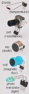
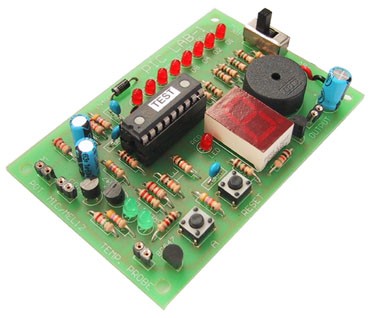
The 5 Input devices and
the PIC LAB-1 complete
The 5 input devices are:
diode,
10k pot, microphone, coil, photo transistor,
This is our first project to span two media. It is designed around the
"beginners" PIC chip, the PIC16F84 and is the first project you
should build (after a PIC programmer) if you want to learn how a PIC
microcontroller works.
PIC LAB-1 article is fairly large in content. Due to the
limitation of space in the magazine POPTRONICS, the outline has been presented
on the printed page, while the full article is here, on the website.
That's one of the advantages of the web, the page is endless. And that's
exactly what we need when producing an instructional article like
this.
Over 25 experiments have been prepared to cover the basic concepts of
programming and the interfacing of a number of devices.
There are lots of other advantages of the web, including the ease of
downloading text and programs for burning into the chip.
The experiments can be pasted into your text editor without the
time-consuming task of typing.
This is a new concept
and we are sure it will continue in the future.
Another big advantage is linkability. Throughout the article we will be
providing links to data, information and theory. Some of these links will take
you to POPTRONICS Interactive Edition, the pay-per-issue e-magazine
that supports this site. Click HERE
to subscribe.
The enormous amount of work that goes into the presentation of the FREE
projects section is covered by readers who subscribe to the e-magazine as
well as those who purchase the kits for each project. If you want
to succeed in this area, you will need to be involved in the practical side by
building the project and carrying out programming.
You are invited to subscribe and
also click the button below to buy a kit and join
the thousands of readers who have purchased a kit from Talking
Electronics.
All the articles, kits and
electronics courses provided by Talking Electronics have been presented in a
completely different way to anything you have seen before.
Everything fits together to
create an enormous educational encyclopedia to get you from the beginning of electronics
to a level that can make you readily employable.
We have documentary proof where readers have skipped over more than 50 other
applicants by merely stating they had read Talking Electronics books and built a number of
their projects. By taking some of our projects to the
interview, your acceptance is virtually guaranteed.
Take this project as a typical example. After studying the PIC LAB-1 project
and carrying out the experiments, you will be capable of writing your
own programs and understanding how to interface devices to a microcontroller.
Showing this type of project, with a laboratory book of say 25 -30 experiments and
explaining your understanding of the concepts, will advance your presentation
at least three rungs up the ladder of acceptance.
A special Readers
Experiments section has been provided on the site map above,
where you can add projects you have created for PIC LAB-1. Simply
email them to Colin Mitchell.
This project is only the beginning. Its potential is almost limitless and it's up to
you to create your own programs and ideas.
Now for the article . . .
But just before we start, I received an email outlining a
program that helps programmers write a program via ICONS. Read my comments
about this program HERE.
If you have ever wondered where to start with PIC microcontrollers, this is
it.
Lots of PIC Programmers and projects using PIC chips have been presented in
books and magazines, but
nothing in the middle - nothing to help the beginner DEVELOP A PROJECT.
PIC LAB-1 shows you how to create programs that collect information from the
outside world and display it on an output device.
It uses the "beginners" microcontroller, a PIC16F84. This chip can be
re-programmed about 1,000 times and is ideal for developing a project.
Projects such as code locks, robot control, vending machine applications,
monitoring, motor control, animation, displays, tones, tunes, invalid aids,
games and signaling are
just a few ideas that are ideal for this chip.
But before you can launch into writing a program, you need to be
thoroughly familiar with the operation of the chip and how to write instructions.
This project has all you need but if you want to know more about how to write
a program, we have a comprehensive course called PIC
PROGRAMMING COURSE on the website. You can see the course
later. There will come a time when your will need to see the additional
information but for the moment we will cover as much as possible to get you
started.
If you have never written a single PIC instruction, click HERE
for your first lesson.
Our method of loading values into a file uses Hexadecimal. Learn about Hex
HERE.
First we start with a pinout of the chip:
The simplest circuit to connect it to the power rails is shown below. The two
components on the clock line (4k7 and 22p) make the chip oscillate at
4MHz and
any instructions programmed into memory will be executed at the rate of 1 million
per second. Pin 4 needs to be taken HIGH. When taken LOW, the chip
resets. Pin 6 is the lowest output line of Port B.
The program in the chip flashes a LED and this is covered in Experiment 1f, on
the following page.
It may seem overkill to use a microcontroller to blink a
LED but this is an example to show how to program the chip. We must
start somewhere and to carry out a simple operation such as this you will need
to have a list of instructions for the chip. Click here for the set of
instructions for a PIC16F84. We have laid them out in a completely
different way to that supplied by the manufacturer of the chip. Our list is much more
understandable and information has been included to help you choose the
right instruction.
More information on the operation of the chip is provided in our PIC
PROGRAMMING COURSE. This is on the pay-site: POPTRONICS Interactive Edition and you need to subscribe for
this section.
This course represents 2 years of collecting information and solving problems
during the designing of projects and is invaluable to help you create a
program.
THE PC BOARD
The PIC LAB-1 Printed Circuit Board is very neatly laid out. It has two amplifying stages so an input of the microcontroller (called an
input line) can be
connected to a coil, microphone, piezo, photo-transistor, potentiometer or a diode (for temperature detection), as well
as a push-button. The output has a row of 8 LEDs and a 7-segment display to show the result of the
information. A complete Multi Chip Programmer
(with
software)
is available on this site as well as a blank programming template to assist you with creating
your own programs. MPASM
is also available on the website to take your .asm
file and assemble it to produce a .hex file for the Multi Chip programmer.
In all, it's a complete package.
It gets you from the absolute beginning, to the stage of producing your
own programs and projects with ease and efficiency. It is not in competition
with anything else on the market as it has been designed to teach PROGRAMMING - at the least cost.