A
Robot
Page 5
A Photovore
driving two clock motors
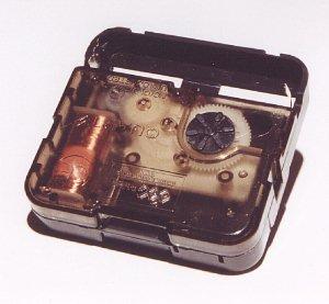
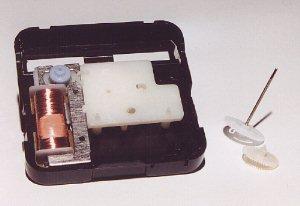
Modifying a
clock The components inside can be clearly seen.
The circuit for the Photovore by Pitronics described on the previous page
is shown below:
The Photovore circuit on the previous page drives a modified clock mechanism.
This is the standard mechanism you find in most "ticking"
clocks. It contains a 1.5v cell and a crystal-driven chip that pulses a
"magnetic rotor" once a second. This motor drives a train of
gears to activate three hands.
Clock motors take very little current and can be easily driven from the output
of gates. Here are the instructions for modifying one of these
mechanisms:
A clock before
modification. Open the case with a screwdriver by spreading the snaplocks.
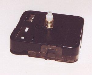
Don't let all the parts fall out.
You have to be able to re-assemble most of the gears.
Remove the first gear and the gear/shaft of
the seconds hand.
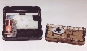
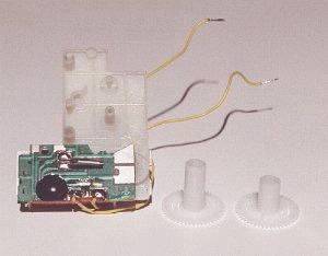
Take the stepping motor plus subframe and PCB
out of the case; they form a single part. Cut the copper foil between the
chip (black lump) and the right coil contact using a small dentist's drill
or a sharp knife. Solder two thin insulated wires (about 5 inches long)
onto the coil. Be careful not to unsolder the coil wires. There
is no need to use different colours: the coil has no plus or minus,
the direction in which the stepping motor rotates is mechanically
determined.
Next to the subframe you see the hour hand gear in
its original form and with its shaft shortened. Cut off 5mm, using a
sharp knife. When you put the clock back together, only the shaft of
the minute hand will protrude from the case, so you can securely
attach a wheel.
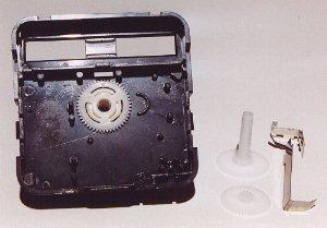
The case with the hour hand gear back in
place. Next to it you see the minute hand gear, the wheel driving the hour
hand, and the two battery contacts. Only leave the minute hand. All the
other gears are removed.
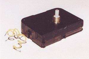
Drill a 3 mm (0.12") hole in the clear
plastic lid, for the wires. The hole should be near the coil. Put
the clock back together. Check its mechanical operation, by temporarily
attaching the seconds hand and turning it carefully. Saw off the battery
compartment using a metal saw. The photo shows the final result. Only the
minute hand shaft protrudes from the case.
HOW THE CIRCUIT
WORKS
The circuit consists of a Solar Engine section and only activates the rest of the circuit when the electrolytic
has sufficient voltage across it.
When the voltage is about 4v, the BC558 (in line with the power rail) gets
turned on and the rest of the circuit is activated.
Two NAND gates form a square-wave oscillator and this signal will be passed to
only one motor at a time, depending on the light received by the photo diodes
or the activation of the feelers.
The two gates connected by a 10M resistor form a bi-stable switch that sits in
either a HIGH or LOW state, depending on the pulse received from the feelers or
photo diode. This HIGH is passed to two NAND gates that drive one of the clock
motors.
If you need to drive 3-pole motors, the
circuit below should be used: