This handy transistor
and LED tester can be built in an evening using spare parts on a small piece
of Matrix Board.
It also highlights an amazing fact about a transformer.
When the voltage (actually the current) is switched off the 40 turn coil in
either of the circuits in this project; the voltage across the coil rises to
more than the 1.5v supply and is in the opposite direction to the voltage of
the supply.
Transistor and LED Tester Circuit
The circuit looks to be
very simple but it uses an air-cored transformer to produce the voltage
needed to illuminate the LED indicators and the circuit only works when the
transistor is connected correctly. There are two separate circuits, one for
NPN transistors and one for PNP transistors. We will cover the NPN section:
The circuit turns ON when the NPN transistor is fitted and the current
through the 30 turn coil and 1k5 resistor turns ON the transistor and
produces expanding flux in the 40 turn coil. This flux cuts the turns of the
30 turn coil and produces a voltage in the coil that adds to the supply
voltage and increases the current into the base. This turns the NPN
transistor ON more. This action continues until the transistor is fully
turned ON. At this point the current in the 40 turn coil is a maximum but it
is not expanding flux and the 30 turn coil ceases to see the extra voltage.
Thus the current into the base reduces and this turns the transistor OFF
slightly. The flux produced by the 40 turn coil now becomes collapsing (or
reducing ) flux and it produces a voltage in the opposite direction to
greatly reduce the current into the base. In a very short period of time the
transistor becomes TURNED OFF and it is effectively removed from the
circuit. The flux in the 40 turn coil collapses quickly and it produces a
voltage in the 40 turn coil that is higher than the supply voltage and is in
the opposite direction. This means the voltage produced by the 40 turns ADDS
to the supply voltage and is delivered to the LEDs to illuminate them.
FLYBACK
The circuit is called
a FLYBACK OSCILLATOR and is characterised by the fact that the transistor
turns off abruptly while the transformer is passing a high current. This
current is producing a high flux density and the abrupt ceasing of the
current causes the flux to collapse and cut the turns of the wire (all
the turns of all the windings) to
produce a voltage in the opposite direction. Because the flux collapses very
quickly, the voltage produced is higher than the supply voltage and this
voltage is added to the supply voltage to produce a result as high as 10v or
more. However, as soon as the voltage reaches 1.7v + 2.3v = 4v, the red and
green LED illuminate and all the energy from the collapsing magnetic field
goes into illuminating the two LEDs.
For the FLYBACK Oscillator to work, the feedback winding (connected to the
base) must be connected so that the voltage (and current) it produces (when
the transistor is turning ON), will ADD to the voltage supplied by the 1k5
resistor, to turn the transistor ON harder. It keeps doing this until the
transistor is fully saturated.
During this "turn-on" period, the primary winding (connected to the
collector) is producing EXPANDING FLUX and this flux is cutting the turns of
the feedback winding and the voltage across the primary winding (about 1v) is
reflected in (passed to) the turns of the feedback winding according to the
ratio of the turns. If 1v is across 40 turns, the feedback winding will see
1/40 x 30 = 0.75v. There is no "flyback" or "high-voltage" produced during
this part of the cycle. The voltage impressed (delivered to) the feedback
winding is called "transformer action" and is determined by the ratio of the
turns and the voltage on the primary winding. The 0.75v is added to the 1.5v delivered by
the 1k5 resistor to produce a higher current into the base of the transistor
and this causes it to turn-ON more. The base of the transistor never rises
above 0.7v and this extra voltage supplied by the feedback winding is
converted to current to produce this part of the cycle.
Understanding how the transformer works is a very important concept.
Normally a flyback transformer is wound on a ferrite core, however air has a
permeability of 1 and will transfer energy via magnetic flux from one coil
to another at low flux densities. If the density is too high, air becomes
saturated and most of the flux will not be transferred, but if the density
is low (as in our case) the transfer will take place and a high voltage will
be produced.
You have to "sit down" and study "transformer action" for hours, until you
understand how the transformer works, because we are talking about energy
being converted from low-voltage, high-current to high-voltage, low-current.
We also talk about a collapsing magnetic field producing a voltage in the
opposite direction. This is one of the magic secrets of how a transformer
works when it is in fly-back mode.
We also talk about the primary producing a high voltage and illuminating one
or more LEDs. When this happens, the primary voltage is "dampened" or
"restricted" or "limited" and this will have an effect on the peak voltage
delivered by the feedback winding. However the feedback winding is also
restricted by the fact that is has a load connected to it in the form of the
base connection of a transistor. This means the feedback winding will not
produce a high voltage during the fly-back portion of the cycle but the
voltage will be high enough to completely turn the transistor OFF.
Now we come to the theory behind the number of turns on the primary and
feedback windings.
The actual resistance of the primary winding is only a few ohms and if the
wire is simply a straight piece of wire, the circuit will take a very high
current and not work AT ALL.
The only reason why it works is due to the fact that the wire is wound in a
coil.
When it is wound in a coil, the current passing through each turn cuts the
other turns and creates an opposing voltage. This voltage makes it difficult
for the applied voltage to cause a hgi current to flow and the current is
considerably reduced. It's only when the transistor is fully turned ON that
the current is no longer increasing and the magnetic flux is no longer
expanding. At this point the current is a maximum by the flux is no longer
cutting the turns of the feedback winding and the transistor starts to turn
OFF.
This action happens very fast and the transistor effectively "comes out of
circuit" and the energy generated by the collapsing flux creates a high
voltage. This voltage is sufficient to illuminate 1, 2 or more LEDs.
As you can see, the circuit is much more complex than first meets the eye
and only after about 100 hours of visually conceiving how the circuit works,
will you be able to see the circuit in action "in your mind."
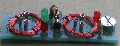
Top view of the Transistor
Tester

The "LED Tester" pins in the centre of the
board
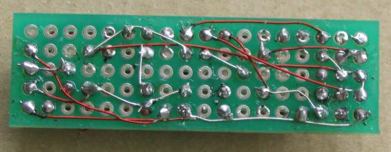
Underside of the Transistor Tester
The NPN circuit has two LEDs in series so that a LED of any colour
(including white) can be connected to the TEST LED terminals and it will
illuminate. You can use any colour LED for any of the LEDs, however it is
best to use either green or yellow or white for the single LED.
The two "coils" are wound on a 10mm dia pen with 0.1mm wire (very fine
wire). The loops of tinned copper wire holding the coils on the board are
connected to separate lands under the board and MUST NOT produce a complete
loop as this will create a “Shorted Turn” and the circuit WILL NOT WORK.
If the LEDs do not illuminate, simply reverse the wires to the 30 turn coil.
The circuit does not need an ON/OFF switch because the LEDs require a
voltage of over 2v to illuminate (the orange LED) and the supply is only
1.5v. A red LED needs about 1.5v to 1.7v to operate but when it is in series
with a green LED, this voltage is over 3.5v.
There are a lot of “design-features” in this simple circuit and it will be
very handy to test transistors as well as LEDs with a low current that will
not damage them.
All the components fit on a small Matrix Board 5 holes x 18 holes. See our
Article on
Matrix Boards.
|
PARTS LIST
Transistor Tester
$4.00 plus $3.00 postage |
|
2 - 1k5
1 - BC547
1 - BC557
1 - red 3mm LED
1 - orange 3mm LED
1 - green 3mm LED
6 - machine pins
1 - 3x component header
1 - 1.5v button cell
30cm - fine solder
20cm - fine tinned copper wire
20cm - enameled wire
1 - 5m+ very fine enamelled wire
1 - 5hole x 18hole Matrix
Board |
A
kit of parts for the project is available for
$4.00 plus $3.00 postage.
Any queries or comments can be emailed to:
Colin Mitchell
3-8-2013
.
|