|
MAKE YOUR OWN CHIPS |
|
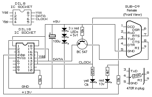
Have you ever wanted to make your own chip? Possibly not, but how would you like to convert a 5-chip project into a single chip? In this series of articles we will show you how to program an 8-pin microcontroller to create a project that originally required 2, 3, 4 or more chips. The first project is very simple and produces effects such as flashing a LED and producing a tone. This will introduce you to the microcontroller and the concept of using a new type of experimental board. The whole idea of these projects is to prove a microcontroller is cheaper than three or more chips and once you build one of the programmers and download the free software, you will have the basis to produce your own chips for your projects. The microcontroller we will be using is the PIC12F629 and its companion: PIC12F675. The '675 has an ADC and this allows it to detect analogue inputs (but is it slightly more expensive). All the projects are backed-up by the availability of a kit so you won’t be left stranded. The kits come with a pre-programmed microcontroller and you will be shown how it can be re-programmed to create additional effects or used for another project. Nothing is wasted. Everything can be re-used and that’s the purpose of the experimenter boards. They are not like an ordinarily printed circuit board. On our Experimenter Boards, the lands are on top and the components are soldered to the lands. This is a much-easier way to develop a circuit as the parts can be easily removed and changed. The other new idea we have introduced is the way the articles are presented. Only the first page will be in the magazine and a link will be provided so you access the rest of the article on the web. We have done this to save paper. Most of the projects will be very long and have lots of photos, so the web is the best place. There are lots of microcontroller development boards on the market but they are far too complex for the beginner. Our development board is low-cost. And the projects are low-cost. We will be starting at the beginning - using just the 35 instructions that come with the micro and show what can be done. The first projects will be simple and they will gradually introduce additional features. We will make programming simple by teaching you how to program using our method of “Copy and Paste.” We will not be introducing any programming language as this adds another level of complexity. Using the instructions that come with the chip is like writing a program with “brief sentences.” Each line contains a set of letters you can understand as each letter represents a word and you can see exactly what the micro is doing. Every line of code in a program is explained with comments after the instruction to further help your understanding. A number of instructions form a group called a sub-routine and a number of sub-routines form a program. Each sub-routine does a “job” such as produce a tone, create a delay, or output a value to a 7-segment display. Other things, such as read a value (either HIGH or LOW) on an input pin or increment a value or compare a value, only require one or two instructions and these are placed in the MAIN part of the program. Programs are written on a pre-prepared template and you simply take sub-routines from the list we provide (called a LIBRARY) and add them to your program. We will show how to create a project using a single 8-pin micro and a few surrounding components. Some of the projects normally require 2 or more chips and lots of components but we will reduced them to 1 chip and a few components – using a micro. Microcontrollers are the way to go. We use only a fraction of the capability of these simple chips as the possibilities are quite extensive. But we get you started. Once you know how to turn an idea into a micro project, you will be able to design circuits you never thought possible. Think along the lines of medical aids, teaching devices or anything you have always wanted. Chances are others will have the same requirement and this is where you can benefit. We will leave it up to you. Kits are available for all projects and the price is low. Here is a list of some of the projects we have developed: 1. Flashing LED 2. Clap switch 3. Electrician’s mate 4. Four Alarm Sounds 5. Logic Probe 6. 50-year timer 7. Burglar Alarm 4-zone 8. IR ON-OFF Remote control 9. Quiz Master 10. 0-10 Counter 11. Running Light Badge 12. RGB LED Driver 13. LED FX 14. Code Lock 15. Sky Writer, Whistle key finder and more Before making any of the projects, you will need to download a number of programs and build a programmer to “program” the microcontroller. We call this “burning the chip” to separate the operation from all the other things you do to the chip during the designing of a project. Originally, chips were “burnt” or programmed using a BURNER and this term has been carried down to identify the operation of loading the chip with instructions and data for the project under development. We have three programmers for this series of projects and the one you will chose will depend on the type of computer you are using. If you have an “old-style” tower computer, you will need our 12 PARTS PIC PROGRAMMER. It is the cheapest and is connected to any of the “old-style” computers with a 9-pin serial port (also called the COM port or RS 232 port). It uses just 12 components plus a lead with 9-pin female socket, 18-pin IC socket and matrix PC board. You can build this project from components in your parts-box or buy it as a kit.
A slightly improved circuit using a Printed Circuit Board is available as a
kit as: MultiChip Programmer.
25-5-2013 |