|
BASIC
ELECTRONICS COURSE
Page 17  INDEX
INDEX

SUMMARY of the points we have covered:
If you need to review a topic, click on the underlined to take you to the page:
Colour-code
Calculator for resistors.
Functions of a resistor:
1. To limit the current in a
circuit
2. To act as a voltage divider
The
Capacitor:
1. Reading capacitor values
2. Capacitors in parallel and series
Functions of a capacitor:
1. To block DC
2. To pass AC
The
LED:
1.The anode and cathode leads
2. The characteristic voltage across
a LED
The
Transistor:
1. turn-on voltage
2. collector-emitter voltage

THE
MULTIVIBRATOR
OR
FLIP FLOP

The first oscillator circuit we will study is the
Multivibrator. This circuit is also called a flip flop as is turns on the left
LED then the right LED in a flip, flop action. This is a very interesting
circuit and it employs the features we have covered in the previous
sections.
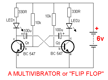
The flip flop circuit is shown above but before we describe
how it works, the animation below shows it in operation. The circuit can be used
as railway crossing lights or for road-works in a model train layout.
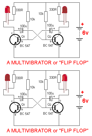
Even though this circuit looks very simple , it has
a lot of features that need explaining.
When the circuit is first turned on, both capacitors
(the capacitors in the circuit are called electrolytics
- see
the section on capacitors
and electrolytics)
are uncharged and they can be taken out of the circuit as shown
in the diagram below to simplify the discussion:
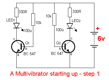
The two 10k base resistors will turn BOTH transistors on at the same time and due to the slightly different
characteristics of the transistors, (their speed of operation), one transistor
will "beat the other" and turn on slightly faster. Suppose Q1
turns on faster than Q2.
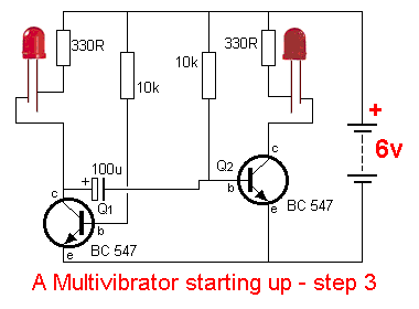
Now put the electrolytics back into circuit. The positive end of the 100u
electrolytic is connected to the collector of this transistor. At the instant
the circuit turns on, the
voltage on the collector will be about 0.7v as it cannot rise any higher than
the "characteristic" base-emitter voltage of the second transistor and
will fall
to about 0.3v when the transistor turns on.
This effect is shown in the circuit
below with the first transistor turned on fully and the electrolytic keeping the
second transistor off.
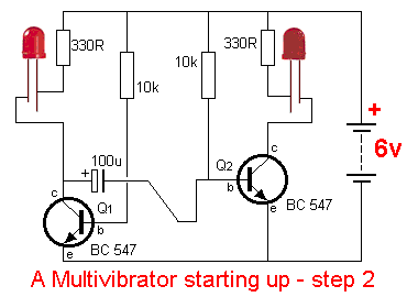
The voltage on the base of the second
transistor falls from 0.6v to 0.2v and the electrolytic charges in the REVERSE
DIRECTION until the base of the second transistor rises to about 0.65v. This is
shown in the diagram below:
The second transistor turns on and its
collector voltage falls, bringing the second electrolytic towards the 0v
rail. This action is shown in the diagram below:
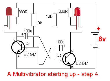
The other end of the second electrolytic is connected to the base of the first
transistor and this turns off the first transistor.
This "change-over" action happens VERY FAST and since the first transistor
is turning off, it is raising the left-hand side of the first electrolytic ,
thus increasing the voltage on the base of the second transistor, (and thus
allowing more current to flow into the base) to turn it on
HARDER.
The second electrolytic is now charged in the reverse direction and after a short period of
time the first transistor turns on and the cycle is repeated.
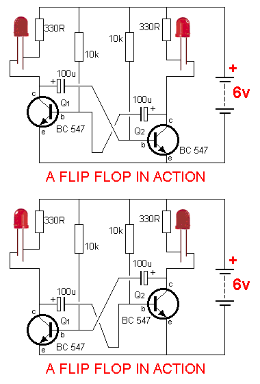
You can think of the two transistor
"jumping up and down" in the circuit, raising and lowering the voltage
on the collector of each. This effect is shown in the animation below and will
help you to understand how the transistors "take it in turn" to
illuminate the LEDs.
Question 69: Name the component that turns the
circuit ON.
Ans: One of the 10k base-bias
resistors.
Question 70. Why does one of the transistors turn on
before the other?
Ans: It has slightly faster
characteristics.
Question 71. Can both transistors turn on at the
same time.
Ans: No. One transistor
"robs" the other of "turn-on voltage," so only one can be on
at a time.
Question 72. How is the "ON" time
determined?
Ans: The ON-time is actually
determined by the OFF time of the other state. If the left-hand-side LED is on,
the left-hand electrolytic is keeping the right-side LED off and the time it
takes this electrolytic to charge and turn the right-hand transistor on, the
"Flip" on-time.
Question 73. How can the frequency of the flashing
be increased?
Ans: The value of the
electrolytics can be decreased or the base-bias resistors can be
decreased.
Question 74. Can the duty cycle for each side be
changed from 50:50?
Ans: Yes. By altering only one
electrolytic or resistor, either side can be made to flash for a shorter or longer
period of time.
Question 75. What is the purpose of the 330R
resistors?
Ans: Current limiting
resistors for the LEDs.
THE
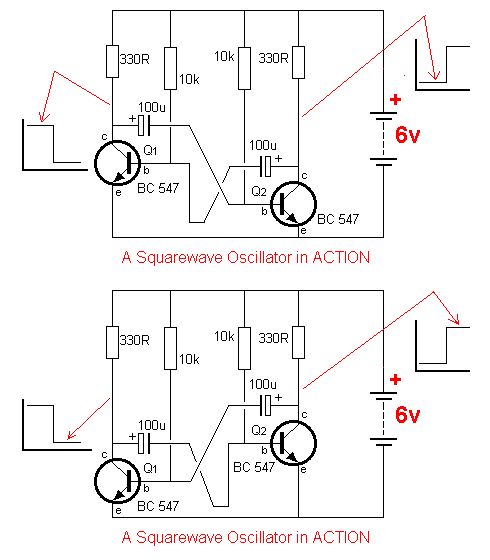
MULTIVIBRATOR AS A SQUARE WAVE OSCILLATOR
Each side of the flip-flop turns ON
very quickly and OFF very quickly and the
graph for this is a square wave as shown in the diagram below.
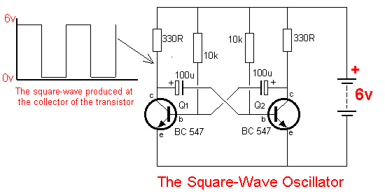
This type of circuit is called a SQUARE WAVE
OSCILLATOR. It is a very important circuit in electronics, especially digital
electronics, where all signals are either ON or OFF and
no mid-values are allowed.
Question 76: When the left-hand transistor is off,
is the collector high or low?
Ans: HIGH.
Question 77: Does the collector of the right-hand
transistor produce a square wave?
Ans: Yes. The only difference
is the output is out-of-phase with the left-hand side. When the left-side is
low, the right-side is HIGH. This is shown in the diagram below:
All the signals in a computer are controlled
by a "CLOCK." This is a square wave oscillator similar to the circuit
above. A "clock" must oscillate at a very high frequency (1MHz or
higher) and by selecting the correct values for the resistors and capacitors
that control the "timing" (the 10k resistors and 100u electrolytics in
the circuit above) the circuit will oscillate at a high
frequency.
In the next section we
change the values (the R-C values) to increase the frequency and show the result
on a CRO.
NEXT

| 


