|
BASIC
ELECTRONICS COURSE
Page 25
 INDEX
INDEX

DIGITAL
CIRCUITS
Up to now we have described circuits without talking about
categories. Circuits can be divided into TWO CATEGORIES: ANALOGUE
and DIGITAL.
If a circuit turns on and off GRADUALLY, it is classified as an
ANALOGUE circuit - such as audio amplifiers, radio circuits
and sinewave oscillators,
If the circuit turns ON and OFF VERY QUICKLY, it is classified
as DIGITAL - such as multivibrators (square wave
oscillators), circuits for turning
on a
LED or globe, and storage circuits. The main reason why a globe
is turned on and off very quickly is so the transistor does not get hot.
This is one of the advantages of a digital circuit. We will
explain this in a moment. There are other
advantages including:
1. It is very reliable in operation (it is either on of off
- and cannot have any "half-on" values)
2. It can store a "bit" of data,
3. It can be made very compact.
In this chapter we will concentrate on the difference
between digital and analogue circuits.
The main characteristic of a digital circuit is it turns on and
off very quickly. This gives the output condition: OFF or
ON. The OFF condition = 0
(zero) and the ON condition = 1. We also say OFF
= LOW and ON = HIGH.
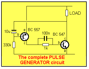
The Pulse Generator circuit is a typical DIGITAL CIRCUIT. The
output is either OFF or ON and it changes from one state to the
other VERY QUICKLY. The animation below shows how the voltage
across the load INCREASES when the circuit turns
ON.
When the output of circuit is LOW, the load is ACTIVATED. The
load may be a globe, motor, relay, siren, speaker, or any other
device. The second circuit shows the voltage across all the
components is very small when it is active so that most of the
rail voltage appears across the LOAD.
There are lots of different DIGITAL CIRCUITS but they have two
things in common.
1. The all switch from HIGH to LOW very quickly,
2. They all deliver RAIL-VOLTAGE when turned ON. In other
words the load sees RAIL VOLTAGE (or very close to full rail
voltage) when the circuit is turned on.
The animation below shows these two features:

HOW
THE CIRCUIT TURNS ON AND OFF
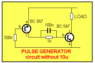
 Firstly you have to see how the
circuit works without 10u electrolytic. Without it, the
circuit turns on immediately and remains ON.
The diagram on the left makes it easy to see how this happens.
The BC 557 transistor is a PNP device and operates as a
"mirror image" of the NPN device. The BC 557 is turned
on via the 330k base resistor and this reduces the resistance
between the collector-emitter leads so that the BC 547
transistor is turned on via the 1k base resistor. The load sees
rail voltage and is activated. Fitting the 10u electrolytic
changes the operation of the circuit completely.

It produces the amazing feature of "pulsing."
The circuit delivers
a short pulse to the load.
When
power is applied the circuit does not turn on
immediately. The 10u is
charged via the 330k (and 1k) and when 0.7v appears across it,
the BC 557 transistor turns on. This causes the BC 547
transistor to turn on and rail voltage is delivered to the
load.
The action of the BC 547 brings the negative end of the 10u
towards the 0v rail and it continues to charge via the
base-emitter junction of the BC 557. The charging current keeps
the circuit hard ON but after a short period of time the
capacitor is nearly charged and the charging current is reduced.
This lower current turns the BC 557
off slightly and
and this action turns the BC 547 transistor off slightly
too. The voltage on the collector rises and this is passed
directly to the base of the BC 557. The slightly lower current
into the base of the BC 557 is multiplied by the gain of the two
transistors and this causes a reduction through the load. The
voltage across the load is proportional to the current through
it and as the current reduces, so does the voltage.
In a very short period of time the two transistors are fully off
and the charge in the 10u is gradually removed by the 330k. This
is a slow process and that's why the off time is considerably
longer than the on time.
SQUARE
WAVE OUTPUT
The output of the Pulse Generator
is a SQUARE WAVE. A square wave does not have to have an
equal On and Off time. It gets its name from the square corners
of the wave.

As shown in the animation, the HIGH and LOW times are different but
the change from one state to the other is very fast.
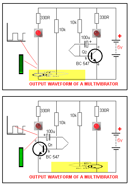
In the animation below we see how each transistor in the
MULTIVIBRATOR (covered in the beginning of this course) turns ON
and OFF. When the transistor turns ON the voltage
across it is LOW and the LED is illuminated. The LED
bargraph indicates a low voltage on the collector of the
transistor when the LED in the circuit is illuminated. The graph
also indicates the voltage on the collector during this
time.

The circuit above is a FREE RUNNING MULTIVIBRATOR or ASTABLE
[(h)ay stable] MULTIVIBRATOR and indicates the
multivibrator has NO stable states. In other words it oscillates
(operates) continually and does not remain permanently in either
state.
There are two other types of multivibrator. They are MONOSTABLE
and BISTABLE.
The MONOSTABLE has one stable state. It is
triggered into its unstable state. The circuit remains in this
state for a period of time then falls back into its stable state
- ready for re-triggering.
The BISTABLE has two states and must be triggered from
one state to the other. The circuit is not capable of changing
states by itself. It remains in either state until triggered
into the other state.
Not long after the introduction of circuits such as the
multivibrator, it was realised the advantage of the bistable
arrangement. It was capable of holding a "bit" of
information. About the same time the US launched its space
project and poured millions of dollars into electronics
research. The result with was the perfection of the
"chip." (The INTEGRATED CIRCUIT)
Some of the first chips were simply transistor stages that
produced an output (HIGH) when the input was HIGH. Other chips produced
an output when two lines were HIGH or when three lines were
HIGH. They called these chips "GATES" (not after Bill
Gates of Microsoft) and created the very first "decision
making" circuits.
On the next page we will cover GATES and show they forged
the way to the introduction of the first "computer."
Question 112: Name a difference between an analogue circuit
and a digital circuit:
Ans: Analogue rises and falls SLOWLY.
Digital rises and falls QUICKLY.
Question 113: Give two names for a HIGH output:
Ans: High = 1 = ON = Active
Question 114: Name the three types of multivibrator circuits:
Ans: Monostable Multivibrator, Bistable
multivibrator, Astable multivibrator.
Question 115: Name the multivibrator with No stable states:
Ans: Astable multivibrator.
Question 116: Name the multivibrator with one stable state:
Ans: Monostable multivibrator.
Question 117: Name the multivibrator with 2 stable states:
Ans: Bistable multivibrator.
Question 118: When a circuit changes state very quickly, is
the output a sinewave or square wave?
Ans: Square wave.
NEXT

| 

 Firstly you have to see how the
circuit works without 10u electrolytic. Without it, the
circuit turns on immediately and remains ON.

