|
|
|
|

|
Introduction

Page 1
INDEX
 |
This PIC Programming Course has been designed to get the BEGINNER into programming the
PIC12C508A and PIC16F84 microcontrollers.
The '508A is the
"baby" in the range with 6 lines that can be configured as input or
output (GP3 can only be an input line) and the 'F84 is the "one-and-a-half-port"
version with 13 lines.
Both of these are very small devices in the
"micro" world but they are the place to start.
Before starting this course we have prepared a discussion by Jim Brown
BSc(Eng), HDipEdAd, GDE (Wits) on the PIC16F84 microcontroller. Just
read the first 25% and come back to our course. You can gradually read the
remainder later.
Click HERE
for the discussion. |
The pin-out for the two chips we are covering in this course
are as follows:
POWERING A
PROJECT
All projects need to be powered from a power-source. This can be a battery,
power-supply or even a set of solar-cells. Click HERE for
an article on Powering A Project.
THE PIC'S
We have chosen these two out of the range of PIC devices as
they are the cheapest and the best (for the beginner). You will see what we mean, AND AGREE, after you read the course.
Maybe you are wondering why we have produced so much information on
programming these chips, as there is already an enormous amount available in
books and on web sites.
The reason is the information is generally of a highly technical nature and
not designed to get the REAL BEGINNER into programming.
What is needed is an absolute beginners course. One that introduces the least
amount of complication to get a program up-and-running.
And that's what we have done. You don't have to know Boolean Algebra, complex
mathematics or the effect of double XOR'ing a file, to be able to program.
We do everything in a simple
way. The course also shows you how to interface the chips to external devices and
by taking ideas from one project and applying them to another you can create a
totally new circuit with the least amount of technical skill.
There's an amazing
thing about programming. A program can be constructed using highly
complex thinking or very simple thinking. The end result is the same but the
simple approach may take a few more instructions to achieve the end result. Who cares
about a few more instructions when the micro is processing at 1,000,000
instructions per second!
We start off with a simple five-line program to turn on a LED with a
PIC12C508A microcontroller.
| SetUp
|
MOVLW 3E ;Make GP0 output
TRIS 06 ;Load TRISB file
|
|
Out0
|
MOVLW 01 ;Load W with 1
MOVWF 06 ;Make GP0 HIGH
GOTO Out0
|
|
| This is the simplest program for the '508A. It turns on a LED as
shown in the animation below: |
Click on the animation below and you will see it turn on the LED connected to
GP0 (General Purpose IN-OUT line ZERO - Pin 7):
This is what the program is doing:
In the first two lines the input/output port is set-up so that the first line
(GP0) is an output.
GP0 is turned ON and this will illuminate the LED connected to the
line. The program goes to the fifth line and is sent back to the third line.
Instructions 3, 4 and form a loop and the micro constantly executes these
until the power is removed.
The diagram above is very simple. The power switch is turned ON and the LED
illuminates.
You don't need a microcontroller to turn on the LED but this is the simplest
circuit to explain how the microcontroller operates.
The important point to note is the operation of the micro. It does not execute the 5
instructions in the program above, then
stop. It keeps going as the oscillator inside the chip keeps
operating all the time. The instruction-set for the PIC12C508A does not have a STOP or HALT
instruction, so you must write the program so that the micro loops around a
number of instructions. These instructions are sometimes called
"do-nothing" instructions.
In the example above, the micro loops around instructions 3, 4 and 5, by
executing 3, 4, 5, 3, 4, 5, 3, 4, 5, etc. The flowchart for the micro is
shown below:
USING A PIC16F84
The same program can be written for the PIC16F84 microcontroller. Although
the two chips do not have exactly the same set of instructions, about 90% of
the instruction-set is the same and in this course we are going to concentrate on the
instructions that are common to both chips.
The instruction to access lines GP0 to GP5, for the PIC12C508A are the same
as accessing RB0 to RB5 for the PIC16F84 chip.
This means many of the programs and projects we will be presenting can be
"burnt" into either chip.
"Burning" is an old name for "programming" and we use it
to
differentiate between the operation of writing a program - commonly called
Programming, from the operation of downloading a program into a chip - also
called Programming.
As soon as a project requires more than 5 or 6 lines (input/output lines)
the PIC16F84 micro will be used.
But this is getting too advanced too quickly, getting back to the simplest
program, it can be "burnt" or "downloaded " into a PIC16F84
and the circuit below will turn on a LED.
The instruction:
MOVWF 06 will turn ON (make HIGH) GP0 for a PIC12C508A
or Line RB0 for a PIC16F84.
The PIC12C508A has an internal oscillator and no external components are
required.
The PIC16F84 has some internal oscillator components and you must add the
timing components (the resistor and capacitor). These two components are shown
in the diagram below:
FLASHING A LED
Suppose you want to make the LED flash with an on-time of 0.1seconds and off-time=0.9seconds. This requires a 4-step program
shown in the Flowchart below:
From
the flow-chart you can see you need to do 4 things:
1. Turn ON an output
2. Keep the output ON for a period of time - called the Delay
time
3. Turn OFF the output
4. Keep the output turned OFF for a period of time - called the
Delay time
The thing you must remember is the processor (the heart of the
microcontroller chip) must be kept running all the time. The
PIC12C508A chip contains a 4MHz oscillator and this frequency is
internally divided by 4 so that one instruction is processed every microsecond.
This makes it very easy to produce accurate delay
routines.
The PIC16F84 chip requires external components to complete the oscillator
circuit. By using a 4k7 and 22p capacitor the oscillator circuit will operate a
4MHz.
In our example we can create a delay by knowing that each instruction takes 1 microsecond to execute
or 2 microseconds if a branch is
involved.
This means we need to produce a sub-routine of
100,000 "DO-NOTHING" cycles to create a delay of 0.1
seconds.
To produce a delay of 0.9 seconds, the delay above is called 9 times.
To create the routine needed to flash the LED, you can start from scratch
by reading the notes we have provided in our chapters or go to the Library
of Routines
chapter.
All the information you need to write a program on a template is contained on
page
24 of this course. The page contains a
.zip
called: BlankF84.zip and the file in
the zip is called BlankF84.asm
Load and save it as detailed on the page. With it you will be able to write programs on a text editor
and run them in a PIC16F84.
These are the lines of code you will need:
FlashLED1
Loop1
AA1
Delay1
DelX
|
BSF 03h,5
MOVLW 00
MOVWF 06
BCF 03h,5
BSF 06,0
CALL Delay1
BCF 06,0
MOVLW 09
MOVWF 0C
CALL Delay1
DECFSZ 0C
GOTO AA1
GOTO
Loop1
MOVLW 82h
MOVWF 1A
DECFSZ 1B
GOTO DelX
DECFSZ 1A
GOTO DelX
RETLW 00
|
;Select
Page1
;to make GP0 output
;Select Page0
;SET bit0 HIGH
;Make bit0 LOW
;Put 9 in W
;0C is the loop file
;130
loops
;256 decrements
;2uS
instruction |
|
This
program turns ON a LED for 0.1sec (Delay1 routine) then OFF for 0.9s
by calling Delay1 nine
times. |
The
following animation shows the result of burning the code into a
'508A: 
The
program can be downloaded into a PIC16F84 and the circuit below will flash a
LED: 
But
just before you rush out and do anything, you must understand that a
PIC12c508A chip can only be burnt ONCE because the cells holding the
program receive a charge during programming and this charge cannot
be removed. The chip is guaranteed to hold a program for many years
but you only use this chip when you are completely satisfied with a
program and the project is ready for completion.
TWO CHIPS
This course concentrates on two chips. The PIC12C508A and PIC16F84. At the
moment you don't know how powerful these chips are and the type of projects
they can drive. This knowledge will come "down the track" so we will
explain our policy:
We firstly try to use a PIC12C508A for a project. If the project requires less than 5 input and/or output lines, the
PIC12C508A will be suitable. If not, you will have to use the PIC16F84.
Programming a PIC16F84 is easy because it is programmed in
the Multi Chip Programmer and placed in the project being developed.
If the project needs a PIC12C508A, you will need an adaptor. The adaptor holds a PIC16F84 and has
oscillator components soldered to the pins. An 8-pin IC socket is soldered to
the 18-pin socket and fits onto the project being developed. The PIC16F84 chip
is taken out of the adaptor and "burnt" in the multi Chip Programmer.
It is then placed into the adaptor and it functions exactly like a PIC12C508A
chip.
When the program works perfectly, you can burn a real PIC12C508A chip and fit it
to the project.
The diagram below shows how the adaptor holds the PIC16F84 chip and plugs into
an 8-pin socket on the project you are developing. 
This
is the cheapest way to design a project with the PIC12C508A chip. Any other way
is very expensive.
The PIC12C508A can
only be programmed ONCE and the development of a project may take 50 or
more "adjustments" until it is operating correctly. You can use 50
PIC12C508A chips or buy the EPROM version. These are
very expensive and you will need at least 5 - 10 because they need
to be erased for 20 minutes before a new program can be written into them and this slows down the
time for development. You will
also need an erasing lamp.
Our 8-pin to 18-pin adaptor costs very little and makes developing a program
very simple.
You can program the PIC16F84 with instructions that suit the PIC12C508A and
the program can be "burnt" into a PIC12C508A.
For the example we have used our Logic Probe project. This project takes an 8-pin
PIC12C508A chip and by using the 8-pin to 18-pin adaptor and a PIC16F84,
a program can be developed at almost NO COST.
One clever trick is to fit a PIC chip to an IC socket and keep the two together
when transferring from the programmer to a project. The chip is much easier to
get out of the socket (in the project) with your fingers. See photo below: 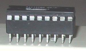
The PIC chip is fitted into an IC socket
for easy removal during programming.
The diagram below shows the PICF84 being burnt on the Multi Chip
Programmer, fitted to the 8-pin to 18-pin adaptor and
plugged into the Logic Probe project.
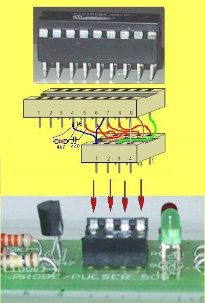
Fitting the PIC chip (and
IC socket) into the adaptor
and into a project under development.
Why do we use the PIC12C508A?
The '508A is much cheaper than the '84 and if your project is very simple,
it is ideal. Very small, cheap projects can be created with the
PIC12C508A and this opens up a whole new field of projects.
The PIC16F84 can be programmed and erased over 1,000 times and is ideal for
development work.
There are lots of projects designed around a PIC12C508A but the
development costs are considerable if you don't use our approach.
As you will read in the chapters, this course is entirely PRACTICAL and it
gets you into programming at the least expense.
Because of this we have not used any of the "STAMP" concepts as
they are very expensive and reduce the capability of the chip enormously.
Our aim is to get you into programming so you can produce microcontroller
projects and sell programmed chips for as little as $5.00 each (in large quantities). This is something that has never been aimed-at before.
That's why this course stands out from everything else.
As soon as you get into PIC programming, you should search the web for PIC user
groups as they have a wealth of valuable information on their sites to help you
understand PIC programming.
The chips we have chosen will allow you to get into creating projects equivalent to 6 or 8 chips
(or even more in
the old technology of gates and counters etc) and produce things such as electronic locks using
card
access, security tags that transmit up to a metre or so, displays, games, telephone devices, alarms,
interfacing devices, oscillators, robotics and lots more. As one programmer
said: "You will never use a 555 again!" Any of the ideas and projects
that have already been produced on and for a "STAMP-type"
module can now be created in a single chip and produced at less than 1/4 of the
cost.
Surprisingly, our course will
have enormous appeal to those already programming with one of these expensive
modules. Quite often an idea will come up that is suitable for marketing. That's
when the project will have to be converted to a much cheaper design to make it
marketable. And that's where we step in. For the cost of a chip and a $5.00
prototyping PC board, you will be able to
launch your own product. But obviously you will have to start at the beginning
and familiarize yourself with the code and capabilities of the chip.
In the next section of this e-magazine we have designed a number of projects
that use both chips. Some of the projects are simple while others are quite
complex. However I can assure you they are less than half the complexity of a
discrete design.
All the programming is
"linear" (very simple) and by going through each line you
will be able to see exactly what is being done at each step.
The biggest problem with the STAMP concept is the cost of duplication. The
first prototype may cost $40 to $70 but additional copies will cost more
than $20. With our approach a fully programmed chip can be sold by
you for $5.00 to $8.00 (they cost as little as $2 in large
quantities), and an assembled PC board for less than $12.00. This
gives you a head-start in the world of marketing and makes you competitive in
manufacturing and selling your ideas.
Many will say the "STAMP concept" gets a program up and running
with very few instructions but we have challenged this by designing a set of
routines to perform many of the operations you will require in the development
of a program and placed them in a LIBRARY OF ROUTINES.
This chapter is included on this site. In this way you can get a program up
and running with very little effort. The advantage of our approach is the micro
runs at full speed, the program memory space can be fully utilized, no
additional chips are required to store the program and all the input-output lines of the chip
are available. There is really no comparison between the two concepts and the differences will not be
mentioned again.
The biggest advantage of doing things our way is you
are fully in-charge of the program. If something doesn't work, you don't have to
wonder if the routine provided by the "STAMP or CLONE" is not doing the operation, or if your code has a bug. By
directly using the micro's instructions (from the
set of approx 33 instructions) you can see exactly what is happening and why it's not
working.
NEXT
|
|