|
TRICKS
with the
INPUT

Page 21
INDEX
CONNECTING A 4x3 KEYBOARD VIA 4 LINES
This discussion shows how to connected a 4x3 keypad to a microcontroller, using
just 4 lines. Normally 7 are needed, but by adding 6 gating diodes, the
requirement can be reduced to 4. This allows 4-core telephone cable to be
used in situations where the keypad is remote from the controlling
circuitry - such as in an alarm situation.
Try the following code-lock. Enter 4 digits and experience the difficulty of breaking
a 4-digit code:
A keypad is a very powerful barrier to entry and when a microcontroller is
controlling the pad, it can be frozen if more than 3 attempts are made. It is
virtually impossible to "crack." If the keypad is "hacked,"
it freezes and the piezo can be programmed to beep every 15 seconds to inform
you of a hacking. And there are lot of other possible features.
A keypad can be used for a number of applications.
1. Dialing telephone numbers,
2. Dialing a code for an alarm or door-entry,
3. Dialing a code for operating equipment such as watering etc.
For simple telephone-number dialing requirements, the keypad can be connected
to an encoder chip as show in in the diagram below. Some encoder chips have 10
or 20 number storage plus redial and other features for telephone use. We are not duplicating already-produced
low-cost LSI
chips.
A keypad connected to an encode chip
Our project caters for alarm or door-entry situations where a code must be
recognised for an operation to be performed.
The discussion will show how a program "makes
decisions" and how GATING (controlling) works.
Our program does only two very simple things: It detects a key and places the value
in a file. Further programming will be given in future articles and projects. This
discussion is only the basics.
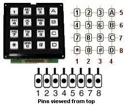
THE KEYPAD
Some keypads have standard pinouts while others have unusual pinouts. You must
refer to the pinout for your particular device. If you are not sure, a
multimeter set to low ohms will detect when a key is pressed. You will also
need a pen and paper to draw a pinout of the pad.
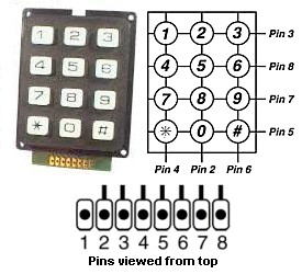
Keypads have different pin-outs.
This is one pinout arrangement.
USING A MICRO
One advantage of a microcontroller is the ability to write a program to carry
out almost any request. This includes recognising incorrect button-presses
to "turn-off" the keypad if fraudulent activity is detected (it
becomes inactive for a period of time).
Another advantage of a PIC microcontroller is the flexibility of
the in/out lines. They can be changed from INPUT to OUTPUT during the running of
a program and this feature has been utilized.
The operation of the program is as follows:
Four lines are required. We have selected the lower four lines of port B.
Line B0 is made a "LOW OUTPUT" and the top row of the 4x3 keypad is "read." This
is how it is read:
B1, B2 and B3 are made inputs (weak pull-up resistors are activated inside
the micro) so the 3 input lines are seen as HIGH if the input port is read and a key is not pressed.
If key 1 is pressed, lines B2 and B3
will be pulled LOW via the diode on each line.
If key 2 is pressed, lines B1 and B3 will be pulled LOW via the diode on each line.
If key 3 is pressed, line B3 will be pulled LOW via the diode on the line.
This gives a unique answer for each key.
On the part of the program, B1 is made LOW and the other lines are made input. This gives
a value for keys 4, 5 and 6.
In the same way the keys in the third and fourth rows are detected.
This is repeated very
quickly to SCAN the whole keypad.
Scanning is repeated at a rate greater
than 20 passes per second and the information can be dealt with by the micro in
a number of ways.
The program can include instructions to generate a DTMF tone or compare a set of
digits with a stored number, to activate/deactivate an alarm or door-entry.
DTMF tones must be produced after Scan. The micro cannot carry out scanning and
produce DTMF tones at the same time. The length of the
tone can be adjusted to suit the quality of the telephone line etc. The
minimum time is 50 milliseconds and can be increased to 200 milliseconds if
needed. Key release is detected and the keypad is then ready for the next keypress. As
soon as the key is pressed, the tone is produced for the pre-determined time and
the micro waits for a key release.
A 4x3 keypad connected via 4 lines
The following table shows the Setting and Reading of the 4 lines and the 12
results. Some of the Readings may be the same, but since each Setting is
different, we generate a unique value for the result by combining the two.
The output value (Setting) on lines B0, B1, B2 and B3
and the input value (Reading) on the lines
The following program consists of a Main routine that calls a sub-routine
called Scan.
This sub-routine scans the keyboard and puts the value of the key (1-9, 0=a,
*=b, #=c) into file 1E, immediately the key is pressed and returns to
Main. The next instruction in Main calls OutputKey. This sub-routine outputs the
key value to a tone encoder chip or to a relay or globe and returns.
The next instruction calls Beep. This subroutine produces a 100
millisecond beep to
identify a key has been recognised. The next instruction calls Release.
This subroutine detects the release of the key before
returning to Main. The micro then goes to the first instruction in Main. The
duration of the beep routine separates keypresses so that a double keypress of the same key
will be correctly
recognised.
|
Main
|
CALL Scan
CALL OutputKey
CALL Beep
CALL Release
GOTO Main |
;Scan Keyboard
;Take key value from file 1E and output to tone chip etc
;Call Beep to recognise key-press (100milliseconds)
;Check for key-release
;Look for next key-press |
|
Scan |
BSF 03,5
MOVLW 0FE
BCF 03,5
CLRF 06
MOVLW 10h
MOVWF 0D
CALL KeyLookUp
BSF 03,5
MOVLW 0FD
BCF 03,5
CLRF 06
MOVLW 20h
MOVWF 0D
CALL KeyLookUp
BSF 03,5
MOVLW 0FB
BCF 03,5
CLRF 06
MOVLW 40h
MOVWF 0D
CALL KeyLookUp
BSF 03,5
MOVLW 0F7
BCF 03,5
CLRF 06
MOVLW 80h
MOVWF 0D
CALL KeyLookUp
RETLW 00
|
;go to page1 to set-up in/out condition
;Make B0 output, others input
;Go to program page (Page0)
;Make B0 LOW
;Store high nibble of key in file 0D
;go to page1 to set-up in/out condition
;Make B1 output, others input
;Go to programming page
;Make B1 LOW
;Store high nibble of key in file 0D
;go to page1 to set-up in/out condition
;Make B2 output, others input
;Go to programming page
;Make B2 LOW
;Store high nibble of key in file 0D
;go to page1 to set-up in/out condition
;Make B3 output, others input
;Go to programming page
;Make B3 LOW
;Store high nibble of key in file 0D
|
|
KeyLookUp
LookUp2
LookUp3
|
MOVF 06,0
ADDWF 0D,1
MOVLW 0C
MOVWF 1D
MOVF 1D,0
CALL Table
XORWF 0D,0
BTFSC 03,2
GOTO LookUp3
DECFSZ 1D,1
GOTO LookUp2
CLRF 1E
RETLW 00
MOVWF 1E
RETLW 00
|
;Read port B (file 06)
;Add unique "Setting" value to file 0D
;0C table values
;Table-byte counter file 1D
;Put table-jump file into W (picks up last value first!)
;Compare table value with file 0D
;Test to find if "SAME" Same=Zbit=1=bit2=set
;Same
;not same
;Look at next byte in table
;Return. Key not found file 1E = 0
;Put key value into file 1E
;Return. Key found. |
|
Table |
ADDLW 02,1
RETLW E2
RETLW E4
RETLW E6
RETLW D1
RETLW D5
RETLW D4
RETLW B3
RETLW B1
RETLW B2
RETLW 75
RETLW 73
RETLW 76
|
;Add W to Program Counter
;1
;2
;3
;4
;5
;6
;7
;8
;9
;0
;*
;#
|
|
OutputKey |
Instruction here
Instruction here
Instruction here
RETLW 00 |
;Instructions
to activate an output
; device |
|
Beep
BeepA
BeepB
|
MOVLW
40h
MOVWF 14h
MOVLW 80h
MOVWF 15h
DECFSZ 15h,1
GOTO BeepB
MOVLW 01
XORWF 05,1
DECFSZ 14h,1
GOTO BeepA
Instruction here
RETLW 00 |
;The
duration of the beep (50mS)
;The loop file
;The duration of HIGH and LOW
;To toggle the lowest line
;Toggle the piezo line
;Turn off output device (if needed)
;Return |
|
Release
|
CALL
Scan
MOVLW 00
XORWF 1E,0
BTFSS 03,2
GOTO Release
RETLW 00 |
;1E will return=0 if no key
pressed
;Put 00 into W
;Compare file 1E with 0
;Look at zero flag Z=Set=Same
;Key not released
;Key released |
TWO
CHOICES
When fitting a keypad to a system, you have two choices. It can be
"active" with the scanning software contained in the chip on the
PC board, along with the keypad. This gives the capability of providing
indicator LEDs, piezo and almost any number of keys.
The downside is the cost of providing a micro for the scanning feature
and a micro for the main section of the project.
The advantage of an active keypad is the capability of adding LEDs and a
piezo. If the system is to be placed in a noisy environment (electrically
noisy), the absence of scanning signals down the lines may result is more
reliable performance.
You need to add
up all the pro's and con's and come up with your own solution.
In my book, the answer is to design a full system with LEDs but charge
less than an equivalent system without LEDs. This way you have an edge on
the opposition.
If you have decided on an on-board micro, the 4 connecting wires will need to be: "5v," "data-ready,"
"data," and "0v." The smallest chip capable of
interfacing a 4x3 keypad is
a PIC12c508A or PIC12c509. If you want to provide indicator LEDs, the
chip should be upgraded to a PIC16F84. Products with this capability are on the
market for $50 to over $100, so you have plenty of margin for marketing your
design.
A 4X4 KEYPAD
A 4x4 keypad can be interfaced to a microcontroller via 4 lines by using an
extension of the gating circuit described above.
The circuit for the 4x4 keypad:
The output value (Setting) on lines B0, B1, B2 and B3
and the input value (Reading) on the lines
ADDING
LEDS
LEDs can be added and multiplexed with the keys with the use of gating transistors. This
can be done with a 4-wire design with the
microcontroller on-board.
The keypad module can also extend to an LCD screen
capable of displaying instructions, time-of-day, temperature, state of the
equipment being controlled and lots more. Obviously this will require a
more-complex design.
This is a very big area and is getting beyond our discussion for this
topic.
Further designs will be presented in our projects section.
NEXT
|