|
The 4017 is a
"decade counter" and this
means it has 10 outputs, starting with output pin 3, only one output
is HIGH at a time. The 10th output is pin 11 and then the counter
starts at pin 3.
The program starts by clocking the 4017 until pin 9 is HIGH. This pin is
connected to the input of the PIC chip and the program now knows the
state of the 4017.
This is called
SYNCHRONISING. See more on this below.
The '628 has two ports, Port A and Port B. Port A has 7 output lines
(plus one input-only line) and
Port B has 8 output lines. This creates our 15 lines for the screen. The
screen is laid out as 15 LEDs "across" and 7 LEDs "down." The data (or
information) is fed in at the top of the screen from the PIC chip to the
15 LEDs and the LEDs are connected to the 0v rail via a transistor that
is driven from the 4107 chip.
Each LED has an 82R resistor in series with the drive-line from the PIC
chip and when you work out the voltage available and the value of the
series resistance, you will find the current is about 30mA.
Since there are 7 rows of LEDs, each row is only turned on for 1/7th of
the total time and this is why you need to drive the LEDs with a high
current, as they are only getting a pulse for a very short period of
time. Pulsing the LEDs like this produces a much brighter result than a
constant current as your eye has a delay (or an extension) in seeing the
illumination - called PERSISTENCE OF VISION and the end result is a very
bright screen.
The top row is turned on for a short
period of time as determined by a delay routine and then the drive-lines
are turned off.
The information for the next line is then placed on the drive-line (port
A and B) and the outputted to the screen. This also clocks the 4017 so
the second row of LEDs is illuminated.
The program does not know which row of LEDs is being illuminated during
the scanning process and that is why it is necessary to synchronize the
two chips when the project is turned on, via a short sub-routine.
For the remainder of the running, the program assumes the two chips
remain in synchronization. There is no reason why this will not be
maintained, but it is not checked or verified at any stage. More on this
under "SYNCHRONISING " below.
This assumption is not allowed in an emergency
environment but is perfectly suitable in our case.
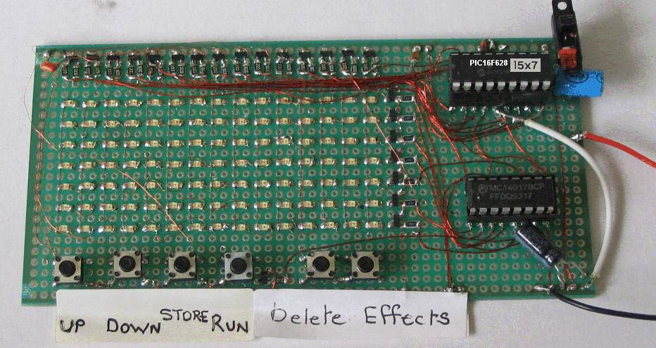
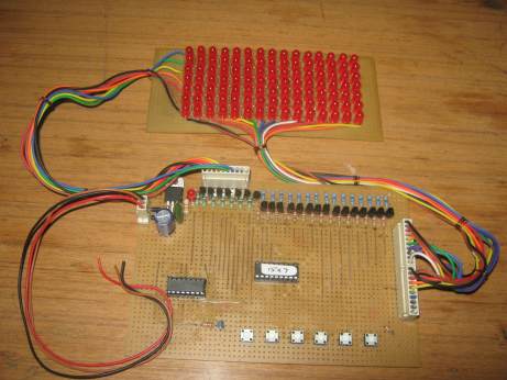
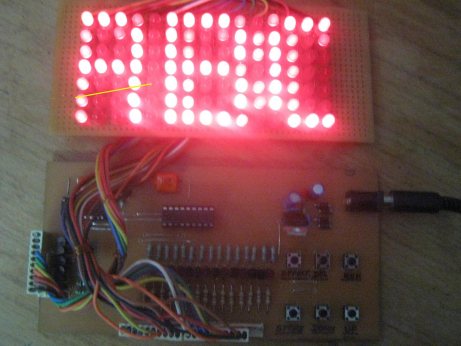
Here is a photo of the project, built by S. Sandhu:
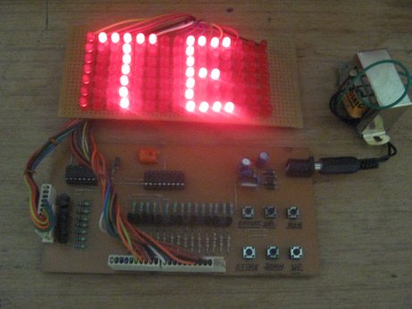
Here are some updates of the project by
S. Sandhu:
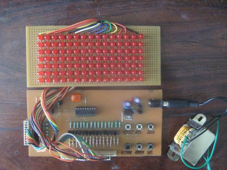
See below for another photo of the project, built by a reader.
THE SUPPLY
The project is powered from 4 AA cells (6v) and when the cells are
fresh, the voltage is slightly too high for reliable operation of the
chip.
A power diode is used to drop the voltage to 5v4 and this is the rail
voltage we have shown as 5v on the circuit diagram.
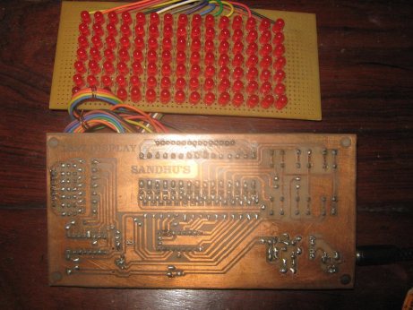
DESIGNING ON MATRIX BOARD
As you can see in the photos, we have built the 15x7 project on a matrix
board.
This is a special PC board, designed by Talking Electronics. It has xx
holes by xx holes at a spacing of 0.1" . This is the normal spacing for
through-hole components but many of the surface-mount components can
also be fitted by placing them so they touch at least one of the lands.
At first appearance, the project may look to be very messy, but after 30
years of designing circuits, this type of board is by the best for this
type of circuit.
When you are designing a circuit, it is very important to have all the
components and wiring on the same side of the board so you can see
everything at the same time.
It is very frustrating to be turning the board over to follow the wiring
from one place to another, especially when a fault develops.
Our type of layout reduces frustration and allows modifications to be
easily implemented.
You can also place the components exactly as they will appear in the
final design and this makes laying out the artwork a lot easier.
By using very fine enamelled wire to join the components, the wiring
almost disappears and the surface-mount components are so small they
take up almost no board-space at all.
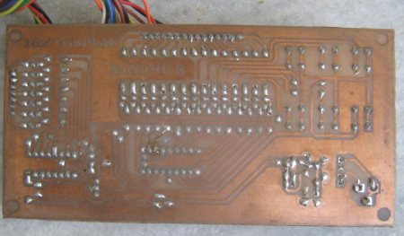
Due to the complex wiring of the LEDs for the display, the final PC
board will have to be double-sided, plate-through hole.
This will allow the tracks for the LEDs to run up and down the board to
connect the columns and from left to right on the underside to pick up
the rows.
A double-sided board also allows long tracks to be run to the switches
etc.
When designing new projects, you need a range of prototyping boards to
suit the circuit and components. Talking Electronics has designed boards
for both through-hole components and surface-mount, including boards for
surface-mount chips.
The most important feature of a prototyping board is the ease of
building and modifying the circuit.
Depending on the complexity and the amount of modifying you will be
carrying out, it is always easier to place both the components and
wiring on the top-side so that everything is visible.
Sometimes a circuit has to be modified many times and the removal of a
component that has been soldered through the board is awkward and
eventually damages the board.
RECAPPING
This
project uses 105 LEDs to produce a screen 15 LEDs long, by 7 LEDs High
for "Running Messages."
This is one of the best projects you can build as it has the widest
application - - in shops, outdoor advertising,
roadside information and lots more - larger signs are just an extension
of the technology you learn in this project.
Larger displays can show more letters but this is the largest display
that can be produced with a single PIC16F628 micro.
The LEDs are scanned by turning on the 15 LEDs along the top row from
the PIC micro and sinking them via a transistor connected to the 4017
chip.
Each of the 15 LEDs is buffered by a transistor so the brightness of the
screen can be a maximum.
After the 7 rows of LEDs, the 4017 accesses the 5 switches and the scan
repeats.
By keeping the scan-rate high, no flicker is detected and the whole
screen can be illuminated to a very high intensity as high-brightness
LEDs are used.
When-ever you create a project as complex as this, there are a lot of
things you have to decide upon and "invent."
After deciding on the direction-of-scan, the letters and numbers have to
be created and placed in a table.
The table (or tables) cannot be longer than a total of 256 bytes for all
the tables as it is very
awkward to access the second page of memory. The first page is actually
called "page 0" and occupies program memory from 000 to 0FFh.
You will notice we have
only put two instructions before the tables, so they can be maximum
length.
The next clever feature of the program is detecting the end of each
character. Instead of placing a "marker" such as 0FFh, we have
incorporated the marker with the last column (last byte) of data.
Refer to the following image showing the letters A to Z and see the last value for
each column is increased by a value of 08h.
The numbers and letters above have been
created by the author but if you want to change the appearance of any
of them, refer to the values in table 2 and change the appropriate byte.
(some of the
formats of the characters can be improved.) The two tables do not use the full
0FFh bytes of the first page of memory. There are twenty six bytes available for your own use.
DETECTING end of character etc etc etc
When writing a program, you have to know where the micro is at any given
time.
The micro can only carry out one operation at a time but since it is
executing instructions at one million per second, it can produce very
impressive results.
Two of the things needed for a table for characters is: (1) the end-value for each
character and (2) the end-marker for the table.
All the characters are placed in a long table and the end-value for
character is simply a value that is not identical to any column-value.
The program can then work out that the value is an end-value. Since 7 lines are used for the columns,
all the values from 01h to 7Fh have been used. The only values available for a
marker are 80h to 0FFh. This involves bit 7, the highest bit in the byte.
In this way it is easy to produce a program to go up or down the table
and produce the letters and numbers. This could be done with a single
table but reversing up the list of characters would require complex
programming.
It is also necessary to know when the end of the table is reached so the
up and down buttons do not pass the end or
start of the list.
The third item that needs to be detected is a SPACE.
SYNCHRONISING
The first output of the 4017 must be active at the time when the PIC
chip is outputting the first row of data and this means the 407 must be
"clocked" so that it is turning on the first output at the
beginning of the scanning cycle.
Since we do not have any spare outputs from the PIC chip to reset the
4017, we have to find another way to achieve this.
We have used the first output of the PIC chip to clock the 4017 and the input-only line, RA5
to detect when the 4017 is at the 9th output. The following sub-routine is used
to clock the 4017 until the PIC chip detects a HIGH on input line RA5:
Set4017 bsf status,rp0
movlw b'00100000' ;Set the TRIS for A in/out
movwf 05h
bcf status,rp0
Set_ movlw b'00000001' ;(turn off RA4) Make RA0 HIGH
movwf 05h
call _10uS
movlw b'00000000' ;Make RA0 LOW
movwf 05h
call _10uS ;clock 4017
btfsc 05h,5 ;see if 4017 is at 9th output
retlw 00
goto Set_
|
The program now knows the 4017 has output 9 HIGH and one clock of the
4017 via the following sub-routine will make the 10th output HIGH:
clock   movlw  b'00000001' ;clock the 4017
	movwf  05h
	call   _10uS
	movlw  b'00000000'
	movwf  05h
	call   _10uS
retlw 00 |
The actual clocking of the 4017 is done via RA0, by taking it HIGH then
LOW and the 4017 is now clocked by the sub-routine SCAN, which scans the
7 rows. In fact it is the presence of data on line RA0 that clocks the
4017 and if line RA0 does not contain data (it will be LOW), the
sub-routine calls the clock routine above.
This is how the 4017 is synchronized with the PIC chip.
For the remainder of the program it is assumed the two chips are "in
step" and there is no reason why this does not occur, if the 4017
receives its correct number of clocking pulses.
We have now clocked the 4017 without using any dedicated
output lines from the PIC chip. This allows us to use all the outputs of
the PIC to control 15 columns of
LEDs on the display.
The next feature of the program is called a "set up" feature.
We need to have a "ghost" screen, equal to or larger, than the display
so that whatever pixel we activate on the ghost display will be
displayed on the actual screen.
This allows us to produce a routine that will easily move the characters
left or right or up and down and whatever is on the ghost screen, will
be displayed without any difficulty.
All the setting-up of the ghost screen and looking at the switches is
done so fast that it does not interfere with the scanning of the
display.
THE RASTER
When the project is turned on, the screen will be blank but it is actually
being scanned at more than 100 frames per second but none of LEDs are activated. The scanning starts at
the top of the screen and moves down, with each row being illuminated in
turn.
This scanning is the same as the production of the white screen on a TV or monitor and is
produced by a separate sub-routine that we will not be concerned with.
If the scan-rate is reduced, you will be able to see the rows being
turned on in sequence. This can be done by increasing the length of the
delay routine associated with the scan sub-routine and you should do this
to see exactly what is happening on the screen.
If we did not scan the screen like this, we would need 105 drive-lines
to drive each LED individually. However LEDs are ideally suited to being turned on and off very
quickly and their performance improves with this "pulse" approach.
The concept is called POV (Persistence Of Vision) and is explained
elsewhere in this article.
When the project is turned on, the program moves the data in files
50h - 5Fh (called the GHOST files) to
70h - 7Fh (called the SCREEN files). If there is no data in the
ghost files, the screen is blank.
The reason why ghost files are needed is simple. Any of the information
we want to put onto the display, must be contained a set of files.
We now have to move the data from the files so it can be shown on the
display. To show a complete screen of date requires 15 files.
How do we take the information from the 15 files and show it on the
screen? Of course you can take each bit for each file and individually
load it into port A and B and display it, but this will take a lot of
programming.
The easiest way is to shift the bits in a file so that the end bit goes
into a location called the "carry." When another file is shifted, the
bit in the carry is loaded into the file. This is a very clever way to
transfer a bit from one file to another.
When this is done with 15 files, the data for the top row is available.
Also the sub-routine for the 15 files can be used again for the second
row etc and thus the lines of code can be kept to a minimum.
This is how the end-bits of 8 files are loaded into a single temporary file
and 7 bits are loaded into another temp file. These two files are then
transferred to port A and Port B. Line RA5
(of port A) is an in-only pin and since it cannot output to the display, an extra
shift is provided in the program to close the gap in the temporary file
by the non-appearance of data from RA5.
It is much easier to work on ghost files when animations are required,
however it is not essential, and you can try manipulating the screen
files, as a challenge.
As you can see from the illustration below, the next letter (letter L)
to be displayed is placed in a set of files that are outside the Ghost
file area and it is very easy to shift the letter into position via a
simple sub-routine.
If you can think of a simpler way to carry out any of these tasks, you
can produce the code and send it in for inclusion in the article. This
is what this article is all about.
After all, some of the smartest software in the world has been produced
by very young, talented, programmers and I am not going to miss any
opportunity to improve the project.
In this world, the more you know, the more you realise you don't know.
BURNING THE CHIP
The PIC chip used in this project is a PIC16F628.
This is an 18 pin device with 16 port-lines plus a pin for 5v and a pin
for ground. It has two ports, called port A and port B. Each port has 8
lines but port A has RA4 as a sinking-line only and RA5 as input only.
This microcontroller chip comes BLANK from the manufacturer and you have
to program it by "burning" a program into its memory. The "burning"
process is called "programming" or simply "writing to the chip."
We have provided some details on this process in the section:
Elektor,EPE,Silicon Chip
The program for the project can be viewed as a
.asm file and each line of code
is explained fully.
When you want to burn the chip, the .hex file is loaded into PICkit2
software called PICkit2 Programer, that comes with the small
plastic box called "Microchip PICkit2," containing lots of surface-mount
components to take the signal on the USB port and produce clock and data
information to burn the chip you
have placed in a socket that is connected to the output of the
programmer.
See photo for chip being programmed:
THE SKY's THE LIMIT
We have provided the basis for all sorts of visual effects.
If you have ever wanted to create your own programs to simulate animated
displays, running signs and traffic control boards, now is your opportunity.
The screen may be small but it is sufficient to produce all sorts of
visual effects and we have provided some basic sub-routines to guide
you.
EFFECTS
The "effects" button is the pathway to the effects. By pushing this
button you can re-name all the other buttons and produce any effect you
like.
All "effects" take the screen data and modify it in some way.
We have already learnt, the data that will be shown on the screen is
stored in a set of files 50h to 68h and these files are called GHOST
FILES.
You will appreciate the concept of storing data in this way, as the
files are easy to manipulate.
This has already been shown with the "running effect" where the letters
are moved across the screen so words and sentences can be displayed.
The sub-routine "shift" creates this effect.
The next simplest effect is called COMPLIMENT.
This effect reverses the color of the letters, similar to white writing
on black background, in printing.
The sub-routine "comp" changes all "1's" into "0's" and "0's" into
"1's."
In this sub-routine, all the illuminated LEDs are turned off and and the
non-illuminated LEDs are turned on.
We do this by taking each file in turn and complementing it.
By calling the "run" sub-routine and adding the complement feature, we
have produced a new effect.
As each column of data is placed in file 5Fh, it is complemented and
"shift" displays it on the screen as reverse lettering.
USING THE PROJECT
When the project is complete and tested, the first thing you will want
to do is produce something on the screen.
The 6 buttons on the project are labeled UP, DOWN, STORE, RUN, DELETE,
and EFFECTS.
These buttons are used to create and scroll a message of up to 7Fh
characters.
Any message is immediately saved in EEPROM and
thus it is not lost when the project is turned off. To write a new
message, the old message must be deleted by pressing the DELETE button
as explained below.
Here is the function of each button:
UP - pressing this button will produce letters A - Z and numbers
1 - 9 then the number zero. The next character is a set of dots on the
lower part of the screen to indicate a space.
DOWN - pressing this button will produce letters in the reverse
order. It can be used to go back to a missed letter or get to a
character quickly without having to advance through the whole list.
STORE - When the required letter appears on the right side of the
screen, the STORE button is pressed. This will store the character in
EEPROM and move the character to the left side of the screen and add a
set of dots on the right side to indicate a place for the next
character. If these dots are STORed, they will show when in the scroll
mode. The space character is explained below.
RUN - When the required number of characters has been stored, the
RUN button is pressed and the message will scroll across the screen. You
can store up to 7Fh characters.
DELETE - pressing this button will remove the last character from
the message when the message is scrolling across the screen. (To scroll
the message, the RUN button is pressed).
EFFECTS - This button will produce all type of effects as
produced by you and other readers, as well as new effects, as they
become available.
WRITING A NEW MESSAGE
To write a new message, the old message must be deleted by pressing the
DELETE button until no character scrolls across the screen.
Start by viewing the old message. Turn the project ON and press RUN. You will see
characters scroll across the screen. Now press the DELETE button until
no character scrolls across the screen.
The project is now turned OFF then ON and is ready for you to create a
new message.
To store a BLANK, press UP to get the letter A, then DOWN to get the row
of 5 dots. This character is then stored as a SPACE. The Space character
(called a BLANK) is located after the numbers and after the number zero.
The 5 dots will not appear in the scroll-mode - just a empty space.
WRITING YOUR OWN SUB-ROUTINES
Before adding anything to the program, you need to look through what has
been written and understand how it works.
Although this project is not very complex, you may want to see some of
the simpler projects and get a grounding on how to write lines of code.
See the left index for other PIC projects.
Each line of code has a comment to let you know what the instruction
does. The layout of the program is alphabetical, with the Main
sub-routine at the end of the program and the delay routines at the
beginning. In this way you will know where to find things.
You can start by getting the "Effects" button to perform a
function.
It can send the micro to a new area of the program in which all the buttons have
a new function or the Effects button can display numbers on the screen
to represent a list of new effects.
You can make the button perform anything at all. You can even create a
sub-routine to scan from
bottom-to-top or create a slow-scan to show how the scanning operation
is carried out.
Firstly, look at the some of the signs in your local neighborhood. See
the effects of flashing, scrolling up, and individual letters
running across the screen. Many of these effects take a long time to
view and the motorist has already passed, before the message has been
delivered.
Consequently, some effects are counter-productive and fail to add to the
delivery of the message.
Since our display is very small, only things like reversal,
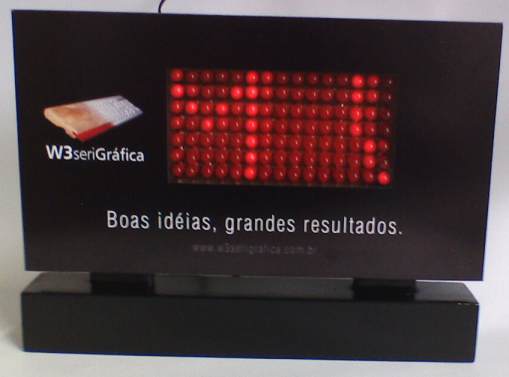
Here is the 15x7 Display produced by one of our readers,
Emilo Konishi:
e-mail:
emilio@w3serigrafica.com.br
W3 Serigrafica
www.w3serigrafica.com.br
Rua Canindé, 86-Jacaré- Rio de Janeiro- RJ- ZIP Code- 20975-010-
Brazil
Phone: + 55 21 3125 3333
Mobile phone: +55 21 8852 7846
More details of the board can be obtained from
Emilo.
Things to come:
Photos of the project showing close-ups of the components
Photos of the programmer, the interface board and the board containing
the IC socket for programming the chip.
23/1/10
|