|
|
|
P2 P3 2N3563.pdf 9014.pdf 9018.pdf Home |

We have covered 27MHz (and 49MHz) links on P1 and P2 of this article and shown how to produce a simple circuit (or buy a toy for less than $10.00) and get 4 or 5 channels.
We also showed how to produce on/off from a single channel and how to detect 27MHz with a Field Strength Meter.
27MHz can transmit at least 100 metres and provide a reliable link as proven by the countless garage-door openers on the market.
But 27MHz transmitters are fairly bulky and need a short antenna to produce a good range.
They are not suitable for short range applications where an antenna is not wanted. These include anything you want to put in your pocket, such as emergency call-buttons, garage door openers, remote car locking, alarm activation/deactivation etc.
For these applications the 303MHz frequency is ideal.
The antenna (the radiator) can be etched onto the PC board and provide an amazing range.
We have tested a 303MHz $10.00 doorbell in open space and achieved a range of 70 metres. It may have operated for a greater distance but we could not hear the doorbell activate!
The range is reduced inside a building but you generally want to see what is happening and 30 to 50 metres is ideal.
For a greater range we have shown how to increase the distance, later in this article.
The two things you will want to do when working on 303MHz transmitters are:
1. Be able to detect 303MHz to see if a transmitter is operating,
2. Determine the output power to compare one transmitter with another.
303MHz TRANSMITTER with 32kHz Crystal
The first circuit we will investigate has a 32kHz crystal to generate a tone so the receiver does not false-trigger.
We have already experienced a fault with a RX-3 circuit. It false triggered every 2 minutes and pulsed the motor for 1 second. As we mentioned before, this could be due to the chip detecting a frequency of 1kHz or 250Hz from the background noise received by the RF transistor, to turn on an output. That's why the RX-3 receiver chip is unreliable. 32kHz is a better frequency to detect as it does not get created from background noise.
The operation of a 303MHz circuit has been covered in our project WIRELESS DOORBELL.
We are not going over how the circuit works but explain the importance of some of the components and how they effect the range.
The Wireless Doorbell transmitter and receiver circuit have been included below:
The most critical component is the transistor.
A quality transistor is important in the RF section and
Japanese transistors are by far the best for this purpose.
The transistor used in the 303MHz oscillator has a maximum frequency of
operation of 1,000MHz and this is where its gain is equal to "1," so we
want a transistor to have a good gain at 300MHz.
A BC 547 transistor will not operate at this frequency so we
have used a 2N 3563 which is low cost and will operate up to 1,000MHz.
The specification sheets for these transistors:
2N3563.pdf
9018.pdf
303MHz TRANSMITTER
using 4069 ICThe following circuit uses a CD 4069 IC to produce the 32kHz tone and 4 gates in parallel to turn the oscillator transistor on and off at the tone-rate.
A single gate will not have enough output to pull the emitter to ground, however 4 gates will bring the emitter close to 0v rail. It must not be at exactly 0v as the 6p will not have an effect in maintaining oscillation.
The chip has 6 gates and when an input is just above mid rail, the output goes LOW. When the input is just below mid rail the output goes HIGH. The gap between detecting a low and a high is not very large and the gate will detect signals called "analogue signals."
But to get the oscillator circuit to start-up, a resistor is placed between output and input.
This will produce an oscillation at the highest frequency for the gate about 500kHz to 2MHz..
When another gate is added and a crystal connected between the output and the input, a "fight" takes place between the signal produced by the 1M and the frequency delivered by the crystal. Since the crystal has a lower impedance than the 1M, it delivers a larger signal to input pin 11 and the two gates operate at the frequency of the crystal.
The exact nature of how the signal from the crystal overtakes the signal fed back from the 1M resistor is not important however if you can consider the first gate starts to increase in frequency from zero, when the signal gets to 32kHz, it starts to activate the crystal and this signal appears on the other side and into the input pin of the first gate.
Both transmitters produce the same result, a 303MHz carrier with a
32kHz modulation (tone - although we cannot hear this frequency). Both
have the same range.
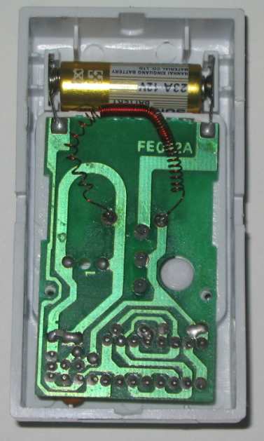
The oscillator coil is also the radiator of the signal and the 1.5uH
inductor on the "centre tap" of the coil can be as high as
10uH or as low as 1.5uH, with little difference in output.
The frequency may have to be adjusted slightly if the inductor is
changed.
We changed it for a 40 turn air-would coil using .25mm wire on
a 2mm former. This increased the range by 1 metre.
A 60 turn coil increased the range a further 3 metres and when it was
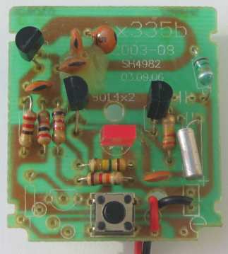
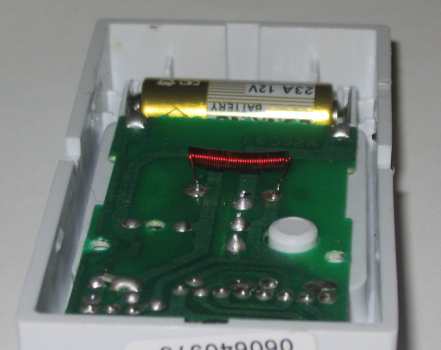
spread out it added to the effect of the antenna. The two photos below
show the placement of these air-inductors.
303MHz RECEIVER
This circuit is almost identical to the Wireless Doorbell article, only
the pin numbering has been changed to suit the layout on the PC board. I suppose, when you are onto a good
circuit, stick to it!
This doorbell cost less than $8.00 and you cannot buy the components
individually for less than that.
This type of circuit makes an ideal basis for experimentation. You can
experiment with the RF side of the circuit as well as the high impedance
sections. Each gate is capable of providing a very high gain and by
putting a 1M from output to input the gate is kept in a state of
excitement, oscillating at approx 500kHz, if no other components
surround the gate to control the frequency. This is designed to keep the
gate active so that the smallest signal will be processed.
In the case of the gate between pins 13 and 12, the 1n capacitor between
the input and ground will reduce the frequency enormously, as well as
the effect of the 2n2 and 5k6 resistor.
The second and third gates simply increase the amplitude of the signal
and do not provide any form of removal of unwanted signals.
The end result is a full amplitude signal at the left-side of the
crystal with all sorts of hash and background noise, but unless the
signal has a 32kHz component, it will not start to oscillate and the
right side will have no signal. The crystal is the component that does
most of the "detection work" and prevents
false triggering as it magically picks out the 32kHz signal from the
"hash" and delivers a very clean signal to the transistor for further amplification.
This signal is amplified further to full rail and charges an
electrolytic to activate a sound chip.
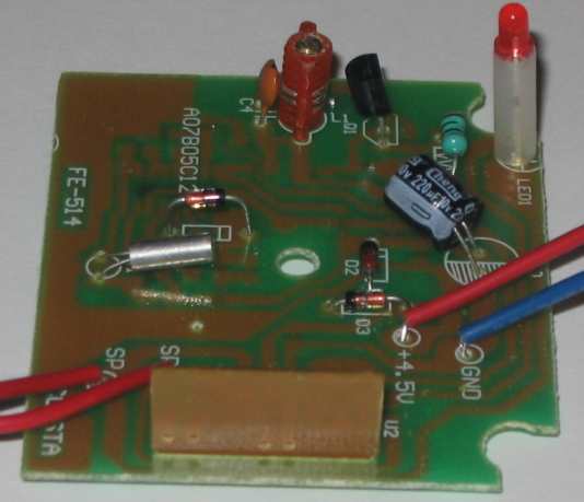
Receiver circuit topside with sound module
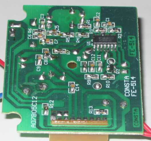
Receiver circuit underside
DETECTING OUTPUT POWER
The output of a 303MHz transmitter can be detected using Field Strength Meter MkII from Talking Electronics.
It needs to be modified to detect this frequency.
The 47p in series with the 4 - 40p air trimmer is replaced with 10p.
The PC coil on the board is cut as shown (to remove it from circuit).
A loop of tinned copper wire is fitted from the negative rail to the 10p land on the board.
This loop now becomes the "pick-up" for the signal and the 47p is turned until the LEDs illuminate to a maximum.
Since none of the transmitters have the frequency set via a crystal,
you will need to use a transmitter with a known frequency to calibrate
the Field Strength Meter. Once this is done you can use it to check the
frequency and output of other transmitters.
Place the loop near the transmitter and adjust the air trimmer for a
maximum.
The position of the pointer will indicate if the transmitter is near the
required frequency.
Since the range of these transmitters is fairly short, the only real way to set the exact frequency is to do a "field test."
Take the transmitter say 20 metres and press the transmit button. Keep moving away and remember the maximum range.
Adjust the coil on the receiver and re-test. If the range increases, you are peaking the coil in the right direction. If the range decreases, turn the slug in the opposite direction.
It will take only a few degrees of adjustment to peak the receiving frequency.
In this way you can compare one transmitter with another.