|
4 CHANNEL REMOTE CONTROL |
|
|
Why re-invent the
wheel?
TRANSMITTER / RECEIVER
SPECIFICATIONS
Transmitter: The transmitter is a
fob-sized case with four buttons.
CONSTRUCTION
4
Channel
9/4/2015
Why design a project from the start when
there are many modules available on the web that can get a project
finished in half the time.
One such module is a 4-Channel remote control.
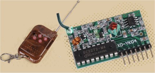
The Transmitter plus the
Receiver costs $5.00
The range is about 30 metres.
1.Operating voltage:
DC12v (27A/12v battery)
2.Operating Current: 10mA @ 12v
3.Radiated power: 10mw @ 12v
4.Modulation mode: ASK (Amplitude Modulation)
5.Transmitting frequency: 315MHz
6.Transmission distance 50-100M (Open field, receiver sensitivity
-100dbm)
7.Encoder types: fixed code
Receiver Board
Operating voltage DC 5v, receiver sensitivity -98db. VT, D3, D2, D1,
D0, +5v, GND.
VT is a valid signal high output pin. Upon receiving a valid signal,
this pin goes HIGH. Can be used to drive a relay.
D3, D2, D1, D0
are the 4 outputs. One of the outputs goes HIGH when a valid
signal is detected.
These buttons can be labelled A, B, C, D or D, C, B, A depending on the
manufacturer and the software has to be written for each type of
transmitter.
The receiver is a very small PC board with the output via a set of pins.
But the transmitter/receiver set-up needs additional circuitry to take the 4 outputs to
control various devices.
It needs either a set of relays or buffer (DRIVER) transistors.
That's what this project does.
It takes the 4 outputs and connects them to a set of 4 driver transistor.
But an additional feature is provided by the microcontroller.
It turns each of the outputs ON or OFF each time the button is pressed.
This project is ideal for so many applications.
You may have a large train layout and you will be able to control 4
items at a distance without the need for wiring.
Or you can open and close gates or animal feeders or watering devices.
You can turn on displays or alarms or anything that needs activation.
The transmitter will work up to about 30 metres and operates at 315MHz
via a transmitting module contained in a 3-leaded metal can, soldered
next to the transmitting coil.
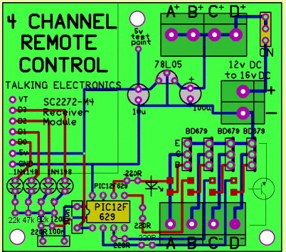
The CIRCUIT
4 channel
remote control circuit
The components
fir on a small PC board and all parts are through-hole, except for the surface-mount
LEDs.
The
PROGRAM
The program only performs a very simple task but doing this with
discrete devices will take at least 6 chips.
You need to detect a long or short tone from 4 channels and provide a
latching circuit.
Rather than sit down and design the necessary circuit, you can use a
microcontroller.
It's just a very convenient way of solving your circuit-designing
problems.
The outputs of the receiver are fed to a 100n capacitor via
different-value resistors.
The diodes are needed because the outputs go low and the resistors not
being used would be taken to 0v and have the effect of reducing the line
that is HIGH.
If the 120k line is HIGH and all the others are LOW, a
voltage-dividing situation would result in a very small voltage on the
100n.
With our arrangement, the voltage on the 100n will be 5v, but the time
taken to reach 5v will be different for each line as the value of the
charging resistor is different.
The micro discharges the 100n via the 220R and then waits to see how
long it takes to charge the 100n.
It then discharges the 100n and waits again.
It keeps doing this to determine if a button has been pushed for a
short period of time or long period of time.
This arrangement has been done because we only have 6 in-out lines on
the PIC12F629 microcontroller chip and 4 lines have been allocated for
the outputs.
The fifth line is INPUT ONLY and does not have the capability of
discharging the 100n.
That means we only have one line available to detect the 4 input lines
(as we need to have a line that can be configured as input and
output).
Many of the sub-routines for this project have already been written and
you can look through previous projects for the instructions.
The micro will be mainly looping around the input. This is called
"polling" the input and it simply discharges the 100n and waits for a
long period of time to see if it has charged. This period of time
represent the time taken for the 120k to charge the 100n. It is only a
few milliseconds, but in computer time this is considerable.
When the 100n is detected as being charged, the micro goes to a
sub-routine to determine which line is HIGH.
The program then toggles the corresponding output.
MORE
For more details on modifying the program and burning the PIC chip, see
Talking
Electronics website and click on
Elektor,EPE,Silicon Chip
in the index.
You can find details of:
PICkit-2 and Adapter connected for In-Circuit Programming
at this link.
Here is the file you will need for "burning" your chip and/or
modifying the program. It comes as .asm, .txt and .hex for using as a
file to modify, or to read, or to burn a new chip:
4Ch-303MHz.asm
4Ch-303MHz.txt
4Ch-303MHz.hex
The kit comes with a pre-programmed PIC chip, see parts
list below.
;****************************************************************
;Started 18/4/2015
;4-Channel 303MHz (313MHz)- Press one of 4 buttons for
;a short time and the corresponding output will toggle.

;****************************************************************
	list	p=12F629
	radix	dec
	include	"p12f629.inc"

	errorlevel -302	; Don't complain about
                     BANK 1 Registers during assembly

	__CONFIG _MCLRE_OFF & _CP_OFF & _WDT_OFF
                   & _INTRC_OSC_NOCLKOUT  ;Internal osc.

;_MCLRE_OFF - master clear must be off for gp3 to work as input pin

;****************************************************************
; variables - names and files
;****************************************************************

temp1	equ 20h	;
temp2	equ 21h	;
temp3	equ 22h	;
temp4	equ 23h	;
_flash	equ 26h ;for flashing the LED


;****************************************************************
;Equates
;****************************************************************
status	equ	0x03
rp1	equ	0x06
rp0	equ	0x05
GPIO 	equ     0x05


status	equ	03h
option_reg	equ 81h


	; bits on GPIO

pin7	equ	0	;GP0  Input from 303MHz module
pin6	equ	1	;GP1  Output A
pin5	equ	2	;GP2  Output B
pin4	equ	3	;GP3  not used
pin3	equ	4	;GP4  Output C
pin2	equ	5	;GP5  Output D


	;bits

rp0	equ	5	;bit 5 of the status register

;****************************************************************
;Beginning of program
;****************************************************************
	org	0x00
	nop
	nop
	nop
	nop
	nop
SetUp	bsf	status, rp0 	;Bank 1
       	movlw	b'11001001'	;Set TRIS  GP1,2,4,5 out GP0,input
	movwf	TRISIO	   	;
	bcf	status, rp0	;bank 0
	movlw   07h         	;turn off Comparator ports
        movwf   CMCON       	;must be placed in bank 0
        clrf    _flash
	clrf 	GPIO       	;Clear GPIO of junk
	goto 	Main

;*********************
;* delays			*
;*********************


	;approx 16uS  delay

_10uS	goto 	$+1
        goto 	$+1
	goto 	$+1
        goto 	$+1
        goto 	$+1
        goto 	$+1
        goto 	$+1
	retlw 	00


_XuS	movlw	.100
	movwf	temp1
_2	nop
	decfsz 	temp1,f
	goto 	_2
	retlw 	00


_1mS	movlw	.2
	movwf	temp2
_1	nop
	decfsz 	temp1,f
	goto 	_1
	decfsz 	temp2,f
	goto 	_1
	retlw 	00


_100mS	movlw	.100
	movwf	temp2
_100	nop
	decfsz 	temp1,f
	goto 	_100
	decfsz 	temp2,f
	goto 	_100
	retlw 	00


_500mS	movlw	0FFh
	movwf	temp2
_500	goto	$+1
	goto	$+1
	decfsz 	temp1,f
	goto 	_500
	decfsz 	temp2,f
	goto 	_500
	retlw 	00


;****************************
;* Sub Routines 			*
;****************************

LED     bsf  	 gpio,1
        call	 _500mS
	bcf  	 gpio,1
        call	 _100mS
        decfsz   _flash,1
        goto     LED
        call	 _500mS
        call	 _500mS
        call	 _500mS
        call	 _500mS
	goto     Main


Toggle	decfsz  _flash,1
        goto    $+4
        movlw 	02
	xorwf	gpio,1	;pin6 button A (1)
	goto    M2
	decfsz  _flash,1
        goto    $+4
        movlw 	02
	xorwf	gpio,1	;pin6 button A (2)
	goto    M2
	decfsz  _flash,1
        goto    $+4
        movlw 	04
	xorwf	gpio,1	;pin5 button B (3)
        goto    M2
	decfsz  _flash,1
        goto    $+4
        movlw 	04
		xorwf	gpio,1	;pin5 button B (4)
        goto    M2
        decfsz  _flash,1
        goto    $+4
        movlw 	04
	xorwf	gpio,1	;pin5 button B (5)
        goto    M2
        decfsz  _flash,1
        goto    $+4
        movlw 	10h
	xorwf	gpio,1	;pin3 button C (6)
	goto    M2
	decfsz  _flash,1
        goto    $+4
        movlw 	10h
	xorwf	gpio,1	;pin3 button C (7)
	goto    M2
        decfsz  _flash,1
        goto    $+4
        movlw 	10h
	xorwf	gpio,1	;pin3 button C (8)
	goto    M2

        decfsz  _flash,1
	goto    $+4
	movlw 	20h
	xorwf	gpio,1  ;pin2 button D (9)
        goto    M2
	decfsz  _flash,1
        goto    $+4
        movlw 	20h
	xorwf	gpio,1  ;pin2 button D (10)
	goto    M2

	decfsz  _flash,1
        goto    M2
        movlw 	20h
	xorwf	gpio,1  ;pin2 button D (11)
	goto    M2


;****************************************************************
;* Main 							*
;****************************************************************

Main	bsf	status, rp0 	;Bank 1
       	bcf 	TRISIO,0        ;make pin7 output
	bcf	status, rp0	;bank 0

	bcf	gpio,0     	;make pin7 low to discharge 100n
        call	_1mS    	;discharge 100n

        bsf	status, rp0 	;Bank 1
       	bsf 	TRISIO,0        ;make pin7 input
	bcf	status, rp0	;bank 0
	nop
	btfss  	gpio,0
	goto    $-2
	bsf	status, rp0 	;Bank 1
       	bcf 	TRISIO,0        ;make pin7 output
	bcf	status, rp0	;bank 0

	bcf	gpio,0     	;make pin7 low to discharge 100n
        call	_1mS    	;discharge 100n
        clrf    _flash
        bsf	status, rp0 	;Bank 1
       	bsf 	TRISIO,0        ;make pin7 input
	bcf	status, rp0	;bank 0

	btfsc  	gpio,0
	goto    Toggle
	incf    _flash,1
	call    _XuS
	goto    $-4

	;switch debounce:

M2      bsf	status, rp0 	;Bank 1
       	bcf 	TRISIO,0        ;make pin7 output
	bcf	status, rp0	;bank 0

	bcf	gpio,0     	;make pin7 low to discharge 100n
        call	_1mS    	;discharge 100n

        bsf	status, rp0 	;Bank 1
       	bsf 	TRISIO,0        ;make pin7 input
	bcf	status, rp0	;bank 0
	call	_1mS
	call	_1mS
	btfsc  	gpio,0
	goto    M2
        goto    Main

	END
Remote Control
Parts List
Cost:$15.00 for the PCB and
components plus $5.00 for the
transmitter/receiver modules
plus $6.50 postage.
Kits
are available
4 -
220R
resistor
1 - 22k
resistor
1 - 47k
resistor
1 - 82k resistor
1 - 120k resistor
2 - 100n monoblock capacitors
1 - 10u 16v electrolytic
1 - 100u 16v electrolytic
4 - 1N4148 diode
4 - SM red LEDs
1 - 78L05 regulator
4 - BD679 transistors
1 - SPDT mini slide switch
1 - 8 pin IC socket
1 - 7-pin socket for
receiver module
5 - 2-pin screw terminals
1 - PIC12F629 chip (with
4Ch routine)
2 - machine pins for logic
probe
1 - 20cm 0.5mm enamelled
wire for antenna
20cm - very fine solder
1 - 4 button remote control
1 - SC2272 Receiver module
1 - 4 Channel PC board
JUST THE MICRO:
Pre-programmed PIC16F629 micro with
4 Channel routine
$5.00 plus $4.50 post