|
Page
10:

THE
TRANSISTOR
Click to see a
table of pinouts
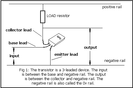
The
transistor is a 3-leaded electronic device. The three leads are given
the names: COLLECTOR, BASE and EMITTER.
In simple terms the input lead is the BASE and the output is the
COLLECTOR.
The EMITTER is connected to the negative rail (for an NPN
type) and is common to the
input and output.
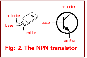
A
typical transistor is shown in Fig: 2 with the equivalent circuit
symbol:
The
transistor is an amplifying device. It has a very close analogy to the
water transistor show in Fig. 3.
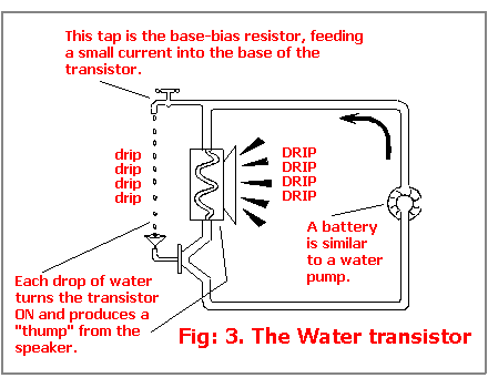
Each
drop of water that enters the base "turns" the
transistor on and causes a larger amount of water to flow through the
speaker to produce a loud "thud" or "click."
This is why the transistor is called an amplifying device.
The only unusual feature with a transistor is the base must be fed
with a small amount of voltage (.6v) before the transistor will allow
current to flow.
This can be equated to putting a few drops of water into the funnel
and then further drops will create a thud.
In general, we can consider the transistor is capable of amplifying
100 times. In other words, if 1mA is fed into the base, 100 milliamps
will flow in the collector-emitter circuit.
Transistors are also capable of amplifying very small currents. If
1/1,000th of a milliamp is fed into the base, the current flow in the
collector will be 1/10th of a milliamp.
PNP AND
NPN TRANSISTORS
There are two types of small-signal transistors. One is called NPN and
the other is PNP. These names are derived from the type of material
used in the manufacture of the junctions.
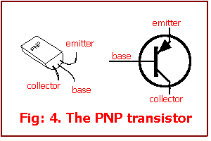
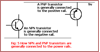
The
PNP type is a mirror image of the NPN type and you will see that the
NPN type is generally connected with its emitter lead to the negative
rail while the PNP has its emitter connected on or near the positive
rail as shown in fig. 5.
It
is very important not to mix up PNP types with NPN types as NPN types
will not work in place of a PNP type and vice versa.
IDENTIFYING
THE TRANSISTORS IN THE KIT
Because this e-book is available world-wide on the web, the type of
transistors you can purchase locally may be different from those we
have described. If you buy a kit locally, the transistors
supplied may be substitutes.
They will work exactly as discussed
but the pinout may not be included in the kit. Click
HERE to see a table of transistor
pinouts. Contact us if the pinout is not included and we will add it
to the table.
We have concentrated on the fact that one of the transistors
is a PNP type and the other is NPN. The circuits we have described are
not critical in operation and will accept almost any type of small
signal transistor - providing they are PNP or NPN.
For a beginner it is not nice to be given an unbranded component or
one with a coloured dot on it but in our case the circuits are so
flexible that the most common types in each country will work
perfectly ok.
In the parts list and on the circuit symbols page we have given a list
of transistors for each type and the first thing you should do is mark
the top of the PNP transistors with red nail polish and the NPN
transistors with white-out. This will keep them separated as it is
very easy to make a mistake and fit the wrong type of transistor.
If we have supplied a transistor not included on the list, we will
have already marked it with a white dot for NPN and red dot for PNP so
that a mistake cannot be made.
WHY WILL
ANY TRANSISTOR WORK?
Almost any transistor will work in our circuits because we are using
them in a non-critical way, on a low voltage and not expecting an
impressive performance. When transistors are manufactured, they are
made in very large batches. They are then tested for collector-emitter breakdown voltage, current gain as well as a number of other
parameters. Every device is then given a type-number and even those
that are left over from the "batching" process are ok for
the circuits in this book. Sometimes you can get unbranded transistors
in junk packs and these will also be suitable.
If you are using parts from your parts-box, the only thing to remember
is to find 4 NPN transistors and 2 PNP transistors. You will also need
to know the pin-out of the leads.
Click
HERE to see a table of transistor
pinouts.
TRANSISTOR
PIN-OUTS
Fortunately transistors have only three leads however there are 6
different ways of naming these three leads and that's exactly what
different manufacturers have done.
Most of the time the pin-out is a result of the way the transistor has been
fabricated however it is important to know the pin out of the devices
you are using as it will take a lot of soldering and desoldering to
try all the different combinations.
We have provided diagrams for the most common devices and a
pin out will be included with any devices used in our kits if they are
not on the list.
BIASING A
TRANSISTOR
There are two resistors that must be connected to a transistor so that
it will work. These are the base-bias resistor and load resistor. For
an NPN transistor, fig 6 shows the placement of the two resistors:
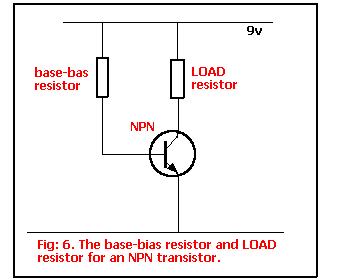
In
Project 1, the base-bias resistor for the NPN transistor is the touch
plate (plus the 47k) and the load resistor is 1k.
The base bias resistor is a very high value so that only a very small
current flows into the base. This is all the transistor needs as it
amplifies the base current at least 100 times and allows the higher
current to flow through the LOAD resistor.
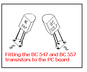
FITTING A
TRANSISTOR
The overlay on the PC Board has a "D" shape showing where
each transistor is placed. The transistors we will
be supplying in the kits will fit exactly over this shape and the
leads will fit down the three holes. The diagrams below show how the
transistors fit down the holes. If you have transistors other than BC
547 or BC 557, the shape of the transistor will be slightly different
and the leads will be in a different position. Refer to the notes
contained in your kit.
|