|
Page
17:
A
great project to teach . . .

FIBRE
OPTICS
This
project uses the "Flip Flop" circuit to create a flashing fibre optic sign
This is
Project #4 on the PC board in "5-PROJECTS"
The display
section of this project is built on a separate PC board contained in
the 5 PROJECTS kit. It has a matrix of very fine holes, 7 holes by 10 holes to take plastic optical fibre, also contained in the kit.
The electronics to drive the display board is the Flip Flop
project built in Project #3 or the single flashing LED from
Project #2.
It all depends if you want a single flashing effect or a dual
flashing effect.
The PC board is shown in the photo below:
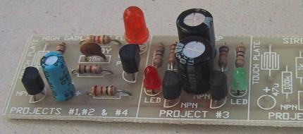
The Fibre Optic project uses the
Flip Flop circuit created in Project #2 or #3
Fibre Optics is the communication medium of the future and its presence will grow with the enormous demand in personal communications. The
advantage of optical fibre is its lightness, small size and it is cheaper than copper. But the biggest advantage is the bandwidth it offers. A single fibre can carry many television channels at the same time, all with perfect digital clarity.
The biggest demand will come from home entertainment; for interactive television, video phone, and global computer networking. The explosion
will be likened to the growth of the home computer industry, some 20 years ago. The Information
Superhighway as they call
it, will be here very soon and the only way to meet the demand for information to every household will be via fibre optic cable.
Basically the cable will take the place of the telephone line and allow television, video and computer channels to enter the home.
In this project we create a very simple fibre optic channel to convey light from a source to a destination.
The type of fibre we are using looks like ordinary fishing line but fishing line will not work. Fibre optic cable is very special in its
construction and the diagram below shows how it works. It is a miniature light guide.
It is not simply a length of plastic line but it has a very thin coating over a clear plastic polymer so that the light entering one end of
the fibre will appear at the other.
MAKING
A FIBRE OPTIC SIGN
The "5 PROJECTS" kit comes with a length of fibre optic cable and a
miniature PC board so you can make a FIBRE OPTIC SIGN suitable for a
model train layout. As shown in the diagram, the fibres are pushed into a
drinking straw or plastic tubing so the light from a LED can can be used to
illuminate the sign.
The reason why the light passes down the fibre and doesn't disappear
out the sides, is due to a phenomenon called total internal reflection.
This is where the light hits the side of the cable and is reflected back into the cable with very little of it escaping to the outside.
The diagram shows one ray of light and the path it takes as it passes down the fibre. The cladding on the outside of the fibre need only
be very thin and it must have a lower refractive index than the main fibre to create internal reflection.
The light hits the side of the cable many times as it passes down the fibre and a very small amount is lost each time it is reflected.
This is why the cable has a limit of about 10 metres before the light is reduced to a level that makes it unusable.
The fibre optic cable we have supplied in the kit is called "plastic." You can also purchase much better quality cable manufactured from
glass but it is extremely brittle and could not be used in this project without breaking.
|
PARTS
LIST: |
|
1
- Flip Flop project #3
1 - 7x10 matrix board (0.7mm holes)
1 - 3m (10ft) plastic fibre optic cable
1 - drinking straw to put over LED |
Optical fibre produces a very small point of light and is ideal for
making a miniature sign for a model layout etc.
The board with 7x10 matrix of holes provided in the kit will allow you to make almost any type of sign and you can create your own designs
on the blank layouts provided and transfer them to the board.
This project allows a wide range of designing and experimenting. The
7x10 matrix can be turned around to a 10x7 arrangement and the sample diagrams give you some idea of the patterns and designs that can
be created.
You can take the ends of the fibres to a single LED or any of the three LEDs on the PC board.
You can also change the LED on the LED Flasher to a HIGH BRIGHT orange LED to create a 3 colour sign.
You will really appreciate the effectiveness of this project if you have a model railway as the most difficult thing to achieve on a layout
is a realistic sign to match the size of the surroundings.
You can create blinking lights around a shop window by running each consecutive fibre to a different LED.
The diagram
above shows how the fibres are placed through the holes in the board and bundled together to fit into a piece of plastic
drinking straw. You can make one, two or three bundles, depending on how complex and colourful you want the sign to be. These bundles then fit over the LEDs on the PC board. Since they flash at different rates and are of different colours, the effect you will create will
be quite interesting.
To keep the fibres in place on the matrix board, the ends are lightly touched with the barrel of a soldering iron. This will make them swell
and prevent them pulling back through the holes. You can then hold the fibres in place with a small amount of glue at the back of the
sign but make sure the glue does not melt them!
To get the best light transfer between the LED and the ends of the fibres, they should all be cut to the same length and the top of the
LED can be flattened and polished.
The 7x10 pattern can be used to create letters or words for a miniature display. In place of the LEDs, a bright lamp can be used to create
an effect that can be seen in daylight.
|