|
5x7 Display
Experiments
Page1

The experiments
start very simple and gradually become more complex. You can use the 5x7
Display Project fully
assembled or only with the PIC chip and one row of LEDs. Both versions will
work for the first 6 experiments.
If you have fitted only the first column of LEDs, you will have to solder a
jumper wire between the collector and emitter of the first transistor so
that the column of LEDs will illuminate when the outputs of the PIC chip go
HIGH.
Only the first column of LEDs are activated in the first 6 experiments and
the "Start" instructions in the program set up the display so that only
these LEDs are activated.
After experiment 6 you will need to completely assemble the project to use the full 5x7 matrix.
These are the items you need:
- the 5x7 Display Project with the first row of LEDs (or fully
built),
- a 6v battery,
- an interface cable
(the components come with the kit)
- a computer.
The 5x7 Display Project comes with a PIC chip containing a test
program. This program tests all the features of the project such as the
LEDs, the 4017 scan chip and the three push buttons.
As soon as you re-program the chip with the code for the first experiment,
you will lose this test program, so you can either use a new chip for the
experiments or down-load the test program again, if you need it.
Don't do any programming unless you you feel you are ready.
Talking Electronics has hundreds of pages of text and projects, both on the
web (and in books and magazines) to get you up to the "ready
state."
If you don't know anything, you can go to our course for beginners, Basic
Electronics Course (BEC Theory. From there you will be shown
links to our books, magazines and kits.
So, if you are ready, here's the start of the programming course:
Before doing any of the experiments, the project can be tested by going to the test pages:
Testing_page1,
Testing_page2,
Testing_page3.
Don't forget, these test experiments are quite complex, so if you want to
start at the beginning, you must start with experiment-1 below:
EXPERIMENT-1 TURN
ON A LED
[If the 4017 chip
and transistors have not been fitted, a jumper will be required between the
collector and emitter of the first transistor as shown in the circuit below]
The first experiment turns on the bottom LED of the first column. That's all
it does. The aim of this experiment is to show you the minimum number of
lines of code required to get the PIC microcontroller to do something.
Firstly there are some set-up instructions we have called Start. The first
instruction tells the assembler to place the program at the
beginning of memory. The second line allows us to access a completely different set of
files to the programming files. Programming instructions are placed at
page0, but in Start or Set-up, at the beginning of a program, we go to
page1 where we find a number of files including files called 05 and
06. These are actually files 85 and 86 and they determine if each pin on port
A and B will be input or output. When a bit in file 85 is 1 the
line corresponding to the bit in port A will be Input and when the bit is 0 the line will be Output.
We cannot load directly into any file and must firstly put a number (called a
literal) into W and
then load W into the file. If W is loaded with 00, and then into 85h and
86h,
all the lines of port A and port B will be made output.
The sixth instruction
closes off this feature and allows programming instructions to be written at
page0.
Instructions 7 and 8 make line RA1 HIGH to reset the 4017 and keep it in reset
for this experiment. Line RA1 is the second lowest line
of "A" port and when it delivers a HIGH to the 4017, the first output
of the chip will be HIGH and this will be delivered to the base
of the first transistor to turn it ON. The result is the cathodes of the
first column of LEDs will be connected to the negative rail so they
will turn on when the outputs of the PIC chip go HIGH.
This means the actual program to turn on a LED consists of 3 lines. The
first line in the LED_ON routine puts 01 into W. The second line moves the
value in W to Port6. This port is the output port (actually an input/output
port) and when the first line of the PIC micro goes HIGH, the bottom LED
(the first LED) will illuminate. The third line loops the program, as
the micro must be incrementing through the program AT ALL TIMES.
To learn more about the instructions we have covered, go to our
PIC
Theory section.
The circuit for the first 6 experiments is shown below:
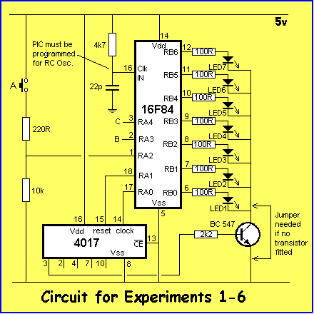
The circuit above
consists of a PIC16F84 microcontroller, a4017 counter chip and a few
additional components. The counter chip starts with pin 3 HIGH when the
reset line is taken HIGH-to-LOW. When the clock line is taken HIGH-to-LOW,
the first output goes LOW and the second output goes HIGH. Each of the first
5 outputs is taken to a "sinking" transistor for the
columns.
Port B of the PIC microcontroller has an LED connected to the first seven
lines and the 8th line is taken to a transistor and piezo diaphragm (not
shown).
The operation of the circuit relies on a program and this program is
contained in the chip. When power is applied, the micro starts at the first
location in memory and executes the program.
The program must be "burnt" into the micro during programming and
at the same time a number of oscillator choices are available. RC osc
(Resistor/Capacitor oscillator) must be selected and the chip is ready to
drive the circuit.
The chip can be programmed and re-programmed over 1,000 times and this makes
it ideal for experimenting.
7 LEDs are available to be turned on in a variety of combinations and the
experiments below are examples of programs to do this:
|
Experiment-1
for "5x7
Display" Project
;PIC16F84 and only F84 chip
;Turns ON bottom left-hand LED
(LED1)
Start ORG 0x00
BSF 03,5
;Go to page1 to set the ports
MOVLW 00h ;Put 00 into W
MOVWF 05h ;Make all RA lines
output
MOVWF 06h ;Make all RB lines output
BCF 03,5
;Go to Page0 for programming
MOVLW 02h ;Put 02 into W to
MOVWF 05h
; Reset the 4017
LED_ON MOVLW 01h ;Put 1 into
W to
MOVWF 06h ; turn on first LED
GOTO LED_ON ;Loop the routine
END
|

Note: The LED turns
on and stays ON.
|
|
|
| The block of numbers
below is the HEX file for Experiment-1. Copy and paste it into a
text program such as TEXTPAD or NOTEPAD and call it:
Expt-1.hex
|
|
|
:10000000831600308500860083120230850001309F
:040010008600072837
:00000001FF
|
You can download
all the .hex files. Click
5x7hex files.
You will also need to download the programming program IC-Prog.
You should also go to the section "Burning
a Chip." This section explains how to load the PIC chip with a .hex
file.
EXPERIMENT-2
FLASH A LED
This experiment flashes the lower left-hand LED and introduces the concept of a DELAY routine.
The microcontroller advances through the program
all the time. It NEVER
stops. For a PIC16F84 with a 4MHz crystal (or 4MHz Resistor/Capacitor
network), the micro advances through one
million instructions per second. (Most instructions take 1 micro-second, but
some - like GOTO and RETURN - take 2micro-seconds).
Between turning on a LED and turning it off again, the micro
needs to carry out about 250,000 instructions called "Do-Nothing"
instructions so that the on/off is slow enough for us to see. The instruction-set has a do-nothing instruction called NOP
(No Operation) but we only have 1,000 memory location, so we cannot fit
250,000 NOP's in a chip. The solution is to create a DELAY ROUTINE. This is
a "do-nothing" or "waiting" routine that takes up computer time until we
want the micro to do the next task. The secret of a Delay routine is the
micro loops around a small number of instructions called an INNER LOOP and
then jumps out to another loop where it carries out a single loop of
instructions that sends it back to the inner loop. Each loop contains a
file that is DECREMENTED and it takes 256 decrements to make a file equal
to zero. It's all simply too complex to describe, so see how it's done in "Chapter
1
The main part of the program is the Flash sub-routine. It puts 1 into W,
then outputs the value to the port where the LEDs are connected. The micro
then goes to the delay routine so that the LED is illuminated. The micro
then goes back to the second half of Flash and puts 00 into W and outputs
zero to turn off the LED. The delay routines is then executed so that the we
can see the LED in the off state. The program then repeats the
operation.
|
Experiment-2
for "5x7 Display" Project
;PIC16F84 and only F84 chip
;Bottom left-hand LED flashes at 2Hz
Start ORG 0x00
BSF 03,5
;Go to page1 for setting-up the ports
MOVLW 00h ;Put 00 into W
MOVWF 05h ;Make all RA lines
output
MOVWF 06h ;Make all RB lines output
BCF 03,5
;Go to Page0 for programming
MOVLW 02h ;Put 02 into W to
MOVWF 05h
; Reset the 4017
Flash MOVLW 01h
;Put 1 into W
MOVWF 06h ; and output to turn on LED
CALL Delay ;Call
Delay
MOVLW 00 ;Put 00 into W
MOVWF 06h ;To turn off LED
CALL Delay ;Call
Delay
GOTO Flash ;Repeat cycle
Delay MOVLW 03
MOVWF 1Ah
Delay1 DECFSZ 1Bh,1
GOTO Delay1
DECFSZ 1Ch,1
GOTO Delay1
DECFSZ 1Ah,1
GOTO Delay1
RETURN
END
|

|
|
|
| The block below is the HEX file for Experiment-2. Copy and paste it into a
text program such as TEXTPAD or NOTEPAD and call it: Expt-2.hex |
|
|
:10000000831600308500860083120230850001309F
:1000100086000E20003086000E20072803309A004C
:0E0020009B0B10289C0B10289A0B1028080030
:00000001FF
|

EXPERIMENT-3 SCAN
UP
The third experiment runs a LED up the first column of LEDs and repeats the
effect. This is done by putting 01 in the output file (file 06h).
This puts a HIGH on the lowest bit and thus the first LED in the column will be
illuminated. The bit is then shifted to the left by a RLF instruction and this
turns on the next LED in the column. It is important to clear the carry flag
before a Rotate instruction is performed as the carry may be HIGH when the
micro is turned on. This will cause two LEDs to travel up the screen - and this
is not wanted!
|
Experiment-3
for "5x7 Display" Project
;PIC16F84 and only F84 chip
;First column of LEDs scan from bottom to top at 2Hz.
Start ORG 0x00
BSF 03,5
;Go to page1 for setting-up the ports
MOVLW 00h ;Put 00 into W
MOVWF 05h ;Make all RA lines
output
MOVWF 06h ;Make all RB lines output
BCF 03,5
;Go to Page0 for programming
MOVLW 02h ;Put 02 into W to
MOVWF 05h
; Reset the 4017
Scan BCF 03h,0
;clear the carry flag
MOVLW 01h
MOVWF 06h
Scan1 CALL Delay
RLF 06h,1
GOTO Scan1
Delay
MOVLW 03
MOVWF 1Ah
Delay1 DECFSZ 1Bh,1
GOTO Delay1
DECFSZ 1Ch,1
GOTO Delay1
DECFSZ 1Ah,1
GOTO Delay1
RETURN
END
|

|
|
|
| The block of numbers
below is the HEX file for Experiment-3. Copy and paste it into a
text program such as TEXTPAD or NOTEPAD and call it: Expt-3.hex |
|
|
:1000000083160030850086008312023085000310BD
:10001000013086000D20860D0A2803309A009B0BC4
:0C0020000F289C0B0F289A0B0F280800DB
:00000001FF
|
EXPERIMENT-4 SCAN
UP & DOWN
The fourth experiment moves the LED up and down the display. It's an
extension of experiment-3 but this time we detect when the HIGH is bit6 (the
top LED turned ON), to reverse the shift and when the HIGH is bit0 to repeat
the cycle.
|
Experiment-4
for "5x7
Display" Project
;PIC16F84 and only F84 chip
;LEDs scan up and down at 2Hz.
Start ORG 0x00
BSF 03,5
;Go to page1 for setting-up the ports
MOVLW 00h ;Put 00 into W
MOVWF 05h ;Make all RA lines
output
MOVWF 06h ;Make all RB lines output
BCF 03,5
;Go to Page0 for programming
MOVLW 02h ;Put 02 into W to
MOVWF 05h
; Reset the 4017
UpDown
BCF 03h,0
;Clear the carry flag
MOVLW 01h ;Turn
on the bottom LED
MOVWF 06h
; and output a HIGH
CALL Delay
UpDown1 RLF 06h,1
;Shift the HIGH up the column
CALL Delay
BTFSS 06h,6 ;Has it reached the top?
GOTO UpDown1 ;NO
UpDown2 RRF 06h,1
;YES. Shift the HIGH down
CALL Delay
BTFSS 06h,0 ;Has it
reached the bottom?
GOTO UpDown2 ;NO.
GOTO UpDown1 ;YES. Repeat the cycle
Delay
MOVLW 03
MOVWF 1Ah
Delay1 DECFSZ 1Bh,1
GOTO Delay1
DECFSZ 1Ch,1
GOTO Delay1
DECFSZ 1Ah,1
GOTO Delay1
RETURN
END
|

|
|
|
| The block of numbers
below is the HEX file for Experiment-4. Copy and paste it into a
text program such as TEXTPAD or NOTEPAD and call it:
Expt-4.hex
|
|
|
:1000000083160030850086008312023085000310BD
:10001000013086001420860D1420061F0B28860C44
:100020001420061C0F280B2803309A009B0B16285F
:0A0030009C0B16289A0B16280800F6
:00000001FF
|
EXPERIMENTS-5A&B
SWITCH DEBOUNCE
This experiment consists of two parts. The first program
"Experiment-5A" toggles a LED on and off via button A but it contains
a very poor DEBOUNCE routine having a short delay. Reduce the Delay routine and
the LED will be very difficult
to control.
|
Experiment-5A
for "5x7
Display" Project
;PIC16F84 and only F84 chip
;Toggling a LED (no de-bounce)
Start ORG 0x00
BSF 03,5
;Go to page1 for setting-up the ports
MOVLW 04h ;Load W with 04
MOVWF 05h ;Make RA2 input for button A
MOVLW 00h ;Put 00 into W
MOVWF 06h ;Make all RB lines output
BCF 03,5
;Go to Page0 for programming
MOVLW 02h ;Put 02 into W to
MOVWF 05h
; Reset the 4017
SwLoop1 BTFSC
05,2
;Is switch A pressed?
GOTO SwLoop1 ;YES. Go to SwLoop1
CALL Delay
SwLoop2 BTFSS 05,2
;Is switch A pressed?
GOTO SwLoop2 ;NO. Go to SwLoop2
MOVLW 01
;YES.
XORWF 06,1
;Toggle the LED
CALL Delay
GOTO SwLoop1
Delay DECFSZ 1Bh,1
GOTO Delay
DECFSZ 1Ch,1
GOTO Delay
RETURN
END
|
|
|
| The block of numbers
below is the HEX file for Experiment-5a. Copy and paste it into a
text program such as TEXTPAD or NOTEPAD and call it:
Expt-5a.hex
|
|
|
:10000000831604308500003086008312003086009D
:1000100002308500051D0A2805190C2801308606C6
:0C0020000A289B0B11289C0B11280800DB
:00000001FF
|
Experiment-5B has an improved de-bounce routine and you will find the LED turns ON or OFF
every time the button is pressed. Fully de-bouncing a push-button is essential
for reliable operation of a project.
The advantage of the program in Experiment 5B is the absence of a delay
routine to cover switch bounce. In any project it is essential to have the
program looping as quickly as possible so that short-duration input pulses
can be detected. If the program is tied up executing a delay routine for
switch-bounce, the input pulse may be missed.
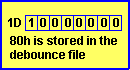
This routine CALLs the Switch routine and it causes very little delay to the
overall running of the program. The 80h loops for debounce (in file 1Dh) creates
reliable operation. Try putting 10h loops into the program and notice the
unreliable operation. The LED turns on and off randomly if the switch is pressed
slowly.
|
Experiment-5B
for "5x7
Display" Project
;PIC16F84 and only F84 chip
;Toggling a LED (with de-bounce)
Start ORG 0x00
BSF 03,5
;Go to page1 for setting-up the ports
MOVLW 04h ;Load W with 04
MOVWF 05h ;Make RA2 input for button A
MOVLW 00h ;Put 00 into W
MOVWF 06h ;Make all RB lines output
BCF 03,5
;Go to Page0 for programming
MOVLW 02h ;Put 02 into W to
MOVWF 05h
; Reset the 4017
MOVLW 00
MOVWF 06h ;Zero the output port
GOTO Main
Switch BTFSC 05,2
;Is switch A pushed?
GOTO Switch2 ;YES.
MOVF 1Dh,0 ;NO. Copy 1Dh into W
XORLW 00
;XOR W with 00
BTFSS 03,2
;Is file 1Dh=0?
GOTO Switch1 ;NO.
RETURN
;YES.
Switch1 DECF 1Dh,1
;Decrement the debounce file
RETURN
Switch2 MOVF 1Dh,0
;1Dh is the debounce file
XORLW 00
BTFSS 03,2
;Is file 1Dh=0?
RETURN
;NO.
MOVLW 01
;YES. LED is on line0 of port6
XORWF 06,1 ;Toggle the LED
MOVLW 80h ;Load W with 80h loops
MOVWF 1Dh ;Put 80h into debounce file
RETURN
Main NOP
;This is a short Main routine to introduce
CALL Switch
; the concept of a CALL from the
NOP
; Main routine
NOP
GOTO Main
END
|
|
|
|
| The block of numbers
below is the HEX file for Experiment-5b. Copy and paste it into a
text program such as TEXTPAD or NOTEPAD and call it:
Expt-5b.hex
|
|
|
:10000000831604308500003086008312023085009C
:10001000003086001E28051D15281D08003A031D06
:10002000122808009D0B000008001D08003A031D5F
:1000300008000130860680309D00080000000B207B
:06004000000000001E2874
:00000001FF
|
EXPERIMENT-6
REACTION GAME
This experiment is actually a GAME. It's a game of skill. The LEDs rise up and
down column 1 and each LED is ON for a short period of time. The middle LED is
the target LED. You have to determine EXACTLY when it is
ON for
HALF ITS DURATION. You have
about 1/20th second to press Button A and no presses
outside this time-frame are accepted. If you press at exactly the right
time, the LED goes out and the game starts again. This game incorporates all the
routines we have covered so far.
There is one fault with the program. It's fairly technical but
"Target" is called from two different locations and if button A
is pushed correctly, the program has a "GOTO Game" instruction. A call
routine should not have a GOTO instruction at the end of the routine as this will upset the stack.
"Target" should be incorporated into the main program in two
places and this is an exercise for you to complete. The second
"target block" should be labelled "Target 4, 5 and 6."
The program has a delay for each LED made up of a half-delay (called Delay)
at the bottom of the program, a very short delay (called Target) where the
program looks for a key-press then another half-delay. During
"Target," the program looks to see if the middle LED is lit, then
checks to see if button A is pressed, then checks to see if button A has
been pressed before the target was lit. If all these decisions are met, the
LED goes off and the game starts again.
Flag file 1Dh, bit 5 is SET when Button A is pushed, and cleared at the
end of each run.
.
|
Experiment-6
for "5x7
Display" Project
;PIC16F84 and only F84 chip
;REACTION GAME - Press button A
Start ORG 0x00
BSF 03,5
;Go to page1 for setting-up the ports
MOVLW 04h ;Load W with 04
MOVWF 05h ;Make RA2 input
MOVLW 00h ;Put 00 into W
MOVWF 06h ;Make all RB lines output
BCF 03,5
;Go to Page0 for programming
MOVLW 02h ;Put 02 into W to
MOVWF 05h ; Reset the 4017
BCF 03h,0
;clear the carry flag
Game MOVLW 01h
;Turn on the bottom LED
MOVWF 06h ; and output a HIGH to LED
CALL Delay
CALL Delay
Game1 BCF 1E,5
;Reset the flag bit for button A
Game2 RLF 06h,1
;Shift the HIGH up the column
CALL Delay
CALL Target
CALL Delay
BTFSS 06h,6
;Has it reached the top?
GOTO Game2
;NO.
Game3 BCF 1E,5
;Reset the flag bit for button A
RRF 06h,1
;Shift the HIGH down
CALL Delay
CALL Target
CALL Delay
BTFSS 06h,0
;Has it reached the bottom?
GOTO Game3
;NO.
GOTO Game1
;YES. Repeat the cycle
Target MOVLW 80h
;This value determines "window" for target
MOVWF 1Ch
Target1 DECFSZ 1B,1
GOTO Target1
BTFSS 06h,3
;Is target LED lit?
GOTO Target2 ;NO.
BTFSC 05h,2 ;Is button A pressed?
GOTO Target3
;YES.
Target2 DECFSZ 1Ch,1 ;NO.
GOTO Target1
RETURN
Target3 BTFSC 1Eh,5
;Has button A been pushed incorrectly?
GOTO Target2 ;YES.
GOTO Game
Delay MOVLW 01h
MOVWF 1Ah
Delay1 DECFSZ 1Bh,1
GOTO Delay1
BTFSC 05h,2 ;Is buttonA
pressed?
BSF 1Eh,5
;Yes. Set flag for button A
DECFSZ 1Ch,1
GOTO Delay1
DECFSZ 1Ah,1
GOTO Delay1
RETURN
END
|
Hit the middle
LED
|
|
|
| The block of numbers
below is the HEX file for Experiment-6. Copy and paste it into a
text program such as TEXTPAD or NOTEPAD and call it:
Expt-6.hex
|
|
|
:10000000831604308500003086008312023085009C
:100010000310013086002A202A209E12860D2A20F5
:100020001C202A20061F0E289E12860C2A201C2027
:100030002A20061C14280D2880309C009B0B1E28AB
:10004000861D2428051927289C0B1E2808009E1AA7
:100050002428092801309A009B0B2C2805199E168C
:0A0060009C0B2C289A0B2C2808009A
:00000001FF
|
The rest of the experiments require the full display of LEDs to be fitted to the project. Fit all the
LEDs, 4017 IC and the "sinking" transistors, as well as the buffer
resistors.
When the project is fully
built and tested, you can continue the experiments.
Go to:
5x7
EXPERIMENTS: Page-2
|