
See TALKING ELECTRONICS WEBSITE
email Colin Mitchell:
talking@tpg.com.au
Save 70 Interesting Circuits as: zip (520kB) or .doc (600kB) or .pdf (600kB) (26-6-2012)
For our other free eBooks:
50 - 555
Circuits
1 -
100 Transistor Circuits
101 -
200 Transistor Circuits
100 IC Circuits
For a list of every electronic symbol, see:
Circuit Symbols.
For more articles and projects to suit the hobbyist: see TALKING ELECTRONICS WEBSITE
| INTRODUCTION This e-book covers a number of interesting circuits. They have been presented for a reason. The original circuits come from an Indian Electronics Magazine and most of them had faults. Either they were over-designed, poorly designed or contained a fault. In the process of bringing these faults and corrections to you, we have created this eBook of 70 Interesting Circuits. You can lean a lot from other peoples mistakes. Not only will you remember not to make the same mistake but the corrections and improvements generally require less components. The art of designing a circuit is to make it as simple as possible and use the least number of components. But before you put a design into production, get someone else to look at it. Another "set of eyes" will see things differently and maybe simplify or improve the design. We have already presented a set of pages called "Spot The Mistake," showing dozens of faulty circuits and how to check and test things before releasing them. It is surprising that a magazine with a readership of over 1,000,000 could publish items with glaring faults. The faulty projects in this collection have a revised circuit included in the article and you can compare the two designs. It only takes a minute to see a circuit will not work and a few more minutes to create a improved design. This is what we are teaching in this section . . . how to look at a circuit with a "critical eye" then design an improvement. This is called REVERSE ENGINEERING and involves the highest level of technical skill. But it is also the fastest way to test a persons skill and the fastest way to learn. That's why I consider it to be the most important approach to learning. Colin Mitchell TALKING ELECTRONICS. talking@tpg.com.au |
|
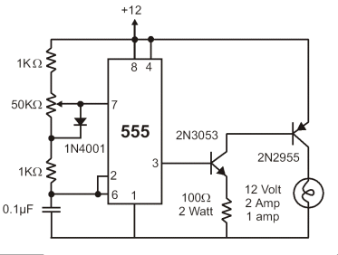
10 OUTPUT LED SEQUENCER Here is 10 output LED sequencer. After the last LED is illuminated, the circuit is reset. This circuit is build around readily available, low cost components - a 555 and decade counter CD4O1 7. The timer IC NE555 is wired as an astable multivibrator that produces 6Hz clock at its output pin 3. The 4017 is a CMOS decade counter with 10 outputs. Inputs include a CLOCK (Pin 1 4), a RESET (Pin 15), and a CLOCK INHIBIT (Pin 13). The clock input connects to a Schmitt trigger for pulse shaping and allows slow clock rise and fall times (not needed in our case). The counter advances one output at the rising edge of the clock signal if the CLOCK INHIBIT line is low. A high RESET signal resets the counter to the zero output. The circuit may be configured for counts less than 10 by connecting RESET to an output pin (one after the desired count). Thus, a five stage sequencer can be made by connecting pin 15 to pin 1. A CARRY-OUT signal (pin 12) can be used to clock subsequent stages in a multi-device counting chain. The output from 1C2 pin 3 is connected to clock pin (pin 14) of the IC3 for sequencing operations. NPN transistors Q1- Q10 are used to increase the output current for the LEDs which is set by the common 150 ohm resistor. In the circuit, only one of the outputs is HIGH at any one time and the output advances by one count with every clock pulse.  But the circuit above is poorly designed. It does not need the voltage regulator as both chips can work up to 15v. The 4017 can supply 10mA to a LED on a 12v supply so that none of the transistors are needed. The circuit below shows the necessary components. The secret to designing a circuit is to look at the final design and ask: "is this component necessary?" Try removing a component and see if the circuit still works. Keep doing this with all the components. The circuit above was published in an Indian magazine with over 1,000,000 readers. The faults were obvious. How these faults passed an editorial committee is beyond me. They are showing very poor design-leadership in allowing this oversight to be published. The faults are technical but are obvious to anyone who has constructed the circuit and experimented with it. Obviously the circuit has never been assembled with anyone with technical expertise. 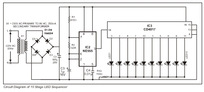 |
|
12v LAMP DIMMER
|
|
16-LED NIGHT RIDER
|
|
555 SCHMITT
|
|
CONSTANT CURRENT SOURCE In the following circuit an LED is used to give a fixed reference voltage to a transistor. The output constant current I out is given by: 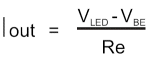 The LED lights up only when a load is connected at the output. Thus it indicates when the circuit is operating.
|
|
AC DETECTOR This circuit will detect AC line currents of about 250mA or more without making any electrical connections to the line. Current is detected by passing on of the AC lines through an inductive pickup (L1) made with a 1 inch diameter U-bolt wound with 800 turns of #35 magnet wire. The pickup can be made from other iron type rings or transformer cores that allows enough space to pass one of the AC lines through the center. Only one of the current carrying lines, either the line or the neutral should be put through the center of the pickup to avoid the fields cancelling. This is most important is very difficult to achieve. The best method is to make a short extension cord with the three conductors separated from each other. If you make a 3-turn loop with say the active line, and pass a straight rod such as a metal bolt, containing 400 or more turns through the centre of the 3-turns, you will produce a very sensitive pick-up. The magnetic pickup produces about 4 millivolts for AC line current of 250mA, or AC load of around 30 watts. The signal from the pickup is increased about 200 times at the output of the op-amp pin 7 which is then peak detected by the capacitor and diode connected to pin 7. The second op-amp is used as a comparator which detects a voltage rise greater than the diode drop. The minimum signal needed to cause the comparator stage output to switch positive is around 800mV which corresponds to about a 30 watt load on the AC line. The output of the 1458 op-amp will only swing within a couple volts of ground so a voltage divider (1k/470) is used to reduce the no signal voltage to about 0.7 volts. An additional diode is added in series with the transistor base to ensure it turns off when the op-amp voltage is 2 volts. You may get a little bit of relay chatter if the AC load is close to the switching point so a larger load of 50 watts or more is recommended. The sensitivity can be increased by adding more turns to the pickup. 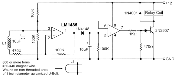 |
|
AUTO CUTOUT A 12v relay is connected across the 12v supply. When the output is shorted, the 12v falls to 0v and the relay drops-out. The contacts open the 12v is reapplied to the relay and it will "chatter" if the short is not removed. This circuit will simply not work and the relay will simply become a "Buzzer."  In the following circuit, the transistor will only turn on if the output voltage is above 0.6v.
|
|
DOOR WATCHER Three reed switches are at the heart of the circuit, one fitted to each door. They close when a door is opened. An associated LED lights when a door is opened. The remainder of the circuit is powered by either D1, D2 or D3. However the 555 is not enabled until pin 4 goes high and this requires the output of either IC1a or IC1b to go high. In turn, this requires either pin 1 ,2 or 4 go high and this happens when a door opens. Because the high on each pin is only momentary (i.e. about 1/3 second, while C1 ,C2 or C3 is charging) there is only a short burst of buzzer activity (two brief beeps) at each door opening, after which it goes mute again. So the beep calls attention to the fact that a door has opened and the LED indicates which door, staying lit until [i door is closed. If another door opens before the first door is closed, there is another beep and another LED lights. 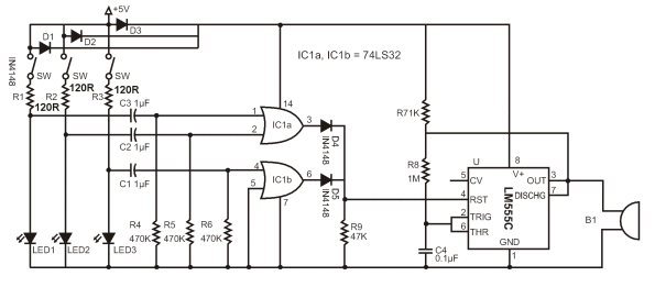 The circuit above is too complex. It is very poorly designed. The 3 signals diodes are doing NOTHING. The are simply across each other!! One diode could be placed in the supply line to the 555 if it is needed for the reset line to work correctly. R7 is not needed as the output is taken to the pins 2&6 and the 74LS32 chip can be replaced by 3 x 470u electrolytics. It can be simplified to this: 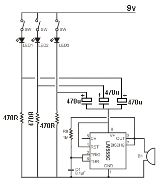 |
|
EMERGENCY LIGHT Here is a circuit of an emergency light. As long as the power supply is present, transistor Q1 conducts. Since the base of the transistor Q2 is connected to the collector of Q1, transistor Q2 and Q3 do not conduct and hence the lamp remains off. LED glows as long as the supply is present. When the power supply fails, the base drive to Q1 disappears. Thus Q1 stops conducting and its collector voltage jumps to battery voltage and starts conducting, switching on the lamp instantly. The load current is supplied by the battery. Whenever the power supply is restored, Q1 starts conducting turning Q2 & Q3 off and the lamp is switched off. Transistor Q2 conducts and provides sufficient base drive to transistor Q3. 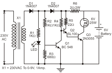 The circuit above is too complex. The first diode is not needed and the rest of the circuit can be re-arranged. The 2R2 will overcharge the battery and dry it out in a few months. It can be simplified to this:  The 100R gives 40mA charging with a 12v battery and 12v DC plug pack. |
|
INCREASING THE INPUT IMPEDANCE The input impedance of a low cost analogue multimeter can be improved using this circuit. The approximate impedance increase will be about 250. The LED provides a fixed reference voltage for zero setting of the multimeter via VR1. 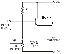 |
|
BATTERY MONITOR This circuit makes it possible to monitor the charging process of a battery. After constructing the circuit, final adjustments are simple and the only thing needed is a digital voltmeter for the necessary accuracy. Connect an input voltage of 12.65 volt between the positive and negative connections of the circuit and adjust the VR1 (10K trimmer) until Led 10 lights up. Lower the voltage and in sequence all other LEDs will light up. Check that Led 1 lights up at approximately 11.85 volts. At 12.65 volt and higher the battery is fully charged, and at 11.85 is considered to be at its lowest state. LED 8, 9 and 10 indicate the battery capacity is more than 50%, LED 4 to LED 7 indicate a capacity of 30% - 50% and LED 1 to LED 3 indicate less that 30%. This circuit, with the components shown, uses less than 10mA. Of course you can adapt it to your own needs by making small modifications. This circuit is set for DOT mode, meaning only one LED at a time will be lit. If you wish to use the BAR mode, connect pin 9 to the positive supply rail, but obviously with increased current consumption. The LED brightness can be adjusted by choosing a different value for the 5k6 resistor connected at pin 6 and 7. The diode 1N4007 was included to protect the circuit from a wrong polarity connection. 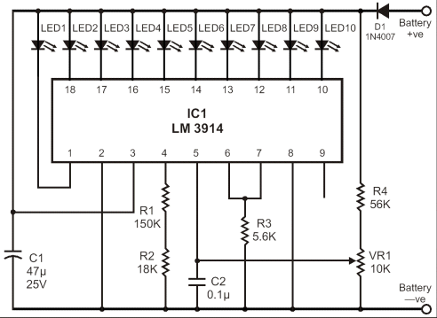 |
|
CAPACITANCE BEEPER Here is a circuit of capacitance beeper which uses a two-transistor flasher in conjunction with a Darlington transistor. When the probe is touched to a capacitor, the project beeps at a frequency that varies with capacitance. The frequency change is so noticeable that small capacitors can be precisely matched or an exact fixed value can be selected to replace a trimmer in a prototype. When the beeper is properly adjusted it draws only 10uA with nothing touching the probe excluding the LED current. This design is optimized for capacitors less than about 100n. Large capacitors give a low frequency clicking sound and small capacitors sound a tone that increases as the capacitance decreases. Many decades of frequency change occur over the beepers range. The probe should be built into a metal box so that one hand makes good contact to 0v. The resistor values are selected to barely turn on the transistors to conserve battery power. The transistors must have very high gain and good low current properties. The MPS-A18 is a very high gain transistor with excellent gain at very low currents. The capacitors are not particularly critical but the trimmer might require a little care. The trimmer is adjusted until the beeping just stops and only a very weak squeal is heard when a 2.2p is touched to the probe. 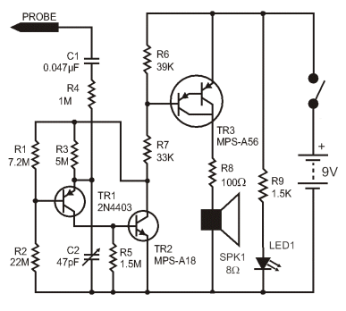 |
|
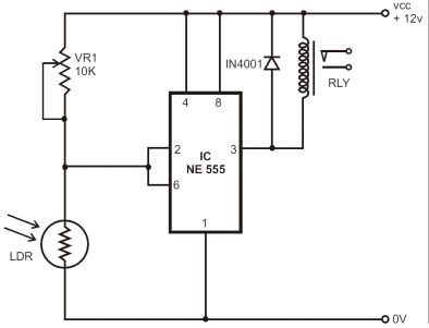
LIGHT CONTROLLED LAMP Here is a circuit of light controlled lamp. This is basically a Schmitt Trigger which receives input from a cadmium sulfide photo cell and controls a relay that can be used to switch a lamp on and off at dawn and dusk. The photo cell should be shielded from the lamp to prevent feedback so the lamp light does not strike the photo cell and switch off the lamp. The photo cell is wired in series with a potentiometer VR1, so the voltage at the base of transistor Q1 can be adjusted to about half the supply, at the desired ambient light level. The two PNP transistors are connected with a common emitter resistor to produce a gap between the on and off voltages - called the HYSTERESIS GAP. Under dark conditions, the photo cell resistance will be high producing a voltage on the base of Q1 that is higher than the base voltage on Q2. This causes Q2 to conduct and activate the relay. The switching points are about 8 volts and 4 volts using the resistor values shown but could be brought closer together by using a lower value for R3. A value of 3k3 would move the levels to about 3.5v and 5.5v. 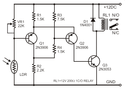 |
|
ELECTRONIC SIREN The 741 is a versatile chip and it can be used in the design of a wide variety of sound-effect generators. This circuit produces a siren that can be used in conjunction with other circuits. You can also use an LM358 dual op-amp chip. The operation of the op-amp was not discussed correctly in the original article, so a full explanation has been provided: The principle of an op-amp is to provide a very high gain. This means a small change in either input produces an almost full rail swing on the output. The circuit starts to work like this. As soon as you put a slight voltage on the "+" input, the output goes full HIGH. The two 100k resistors on the "+" makes the output go full HIGH. Now we connect a resistor from the output to "+" and this makes no difference. The output remains full HIGH. Now we put a resistor from output to "-." If the "-" input is slightly higher than "+" the output goes LOW. This is what happens. The output voltage drops until the "-" input is slightly lower than the "+" input and that's why the output falls until its voltage is equal to the "+" input. Now we connect a capacitor to the "-" input. It does not matter if we add the capacitor later or turn the circuit on with the capacitor fitted. The voltage on the "-" input will be lower than the "+" input and this will start the circuit oscillating. This is how it oscillates: Because the "-" input is lower than the "+" input, the output rises towards the positive rail and this begins to charge the capacitor. The voltage on the "-" input can rise higher than the "+" input and when it is about 15mV higher, the output drops towards the 0v rail. This reduces the voltage on the "+"input and the capacitor has to discharge a considerable amount before it is lower than the "+" rail. (Actually before the "+" input is higher than the "-" input). The voltage on the "+" input is rising and falling by about 30% of rail voltage and this is the amount the capacitor has to charge and discharge for the circuit to work. 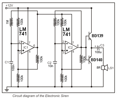
|
|
LIGHTENING DETECTOR Clouds can carry such huge electric charges that may to cause lightning flashes of thousands of volts. It is really a fascinating phenomenon. When a lightning flash takes place a broad spectrum of radio-frequencies is generated. In this broad spectrum there is special intense emissions of the VLF (Very Low Frequency) band. This project will allow you to build a receiver to pick up a band near 300 KHz. An LED will flash to indicate the lightning flashes. THE CIRCUIT The radio-signal generated by the lightning flash is picked up by the telescopic antenna with the help of a 10mH choke. The choke L1 resonates with the antenna and allows current to flow into the receiver circuit. The L2 of 330uH in parallel with the 680pF capacitor C1 forms a tuned circuit for 300KHz. This parallel-tuned tank circuit is coupled to the base of Q1 via D2. The amplified radio signal is again coupled into the base of Q2. Transistors Q2 and Q3 form an LED flasher circuit. Transistor Q4 is the LED driver. The flasher is biased so that when VR1 is carefully adjusted the LED flashes only when a radio burst appears at the input due to a lightning flash. Positive feedback ensures the LED to be full on. The circuit quickly resets by charging C4 capacitor through diode D1. The circuit draws only about 100uA in idle state. Therefore it can run on two cells for many hours. 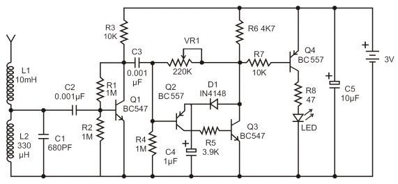 |
|
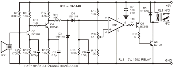
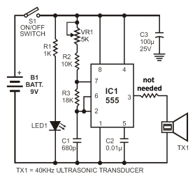
ULTRASONIC REMOTE CONTROL Here is a low cost, wireless switch controller. It uses ultrasonic sound waves for remote control of a switch. As with any other remote control, the system basically comprises a transmitter and a receiver circuit. Frequencies up to 20kHz are audible. Frequencies above 20kHz are not audible. The transmitter circuit generates an ultrasonic frequency between 40-50kHz. The receiver senses the ultrasonic sound and switches on a relay. The transmitter uses a 555 astable multivibrator. It oscillates at a frequency of 40-50kHz. An ultrasonic transducer is used to transmit the frequency. The transmitter runs on a 9v battery. The ultrasonic receiver uses a receiver transducer to sense ultrasonic signals. It uses a two-stage amplifier, a rectifier stage and an operational amplifier in inverting mode. Output of the operational amplifier is connected to a relay through a driver stage. A 9v adapter can be used to power the receiver circuit. When switch S1 is pressed, it generates ultrasonic sound. The receiver amplifies the received signal via transistors Q3 and Q4. The amplified signal are then rectified and filtered. The filtered DC voltage is given to the inverting pin of operational amplifier 1C2. The non-inverting pin of 1C2 is connected to a DC voltage through VR2 that determines the threshold value of the signal received, for operation of relay RL1. The inverted output of 1C2 is used to bias transistor Q5. When transistor Q5 conducts, it supplies base bias to transistor Q6. When transistor Q6 conducts, it energises the relay RL1 . The relay can be used to control any electrical or electronic appliance. Frequency of the circuit can be varied by adjusting VR1. Adjust it for maximum performance. Ultrasonic sounds are highly directional. So when you are using the transmitter, the receiver should face towards the transmitter. The receiver is always kept on. 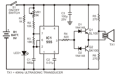
|
|
MOVING LEDs Here is another disastrous circuit. As each output goes high it pulls the previous output high to turn on two, three, four LEDs etc. But any output that is not high is PULLED LOW by the chip and this circuit is pulling the outputs HIGH against the drivers inside the chip. This could lead to failure and certainly will heat up the chip. This circuit is a bad design and is not recommended. 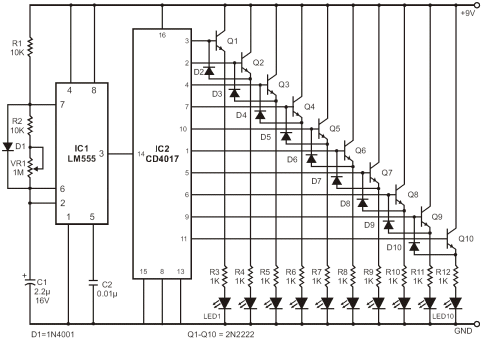 |
|
ON-OFF SWITCH Here's how industrial equipment is started and stopped using momentary pushbuttons. The circuit is called a "locked-out relay." It uses an ordinary relay and the ON switch activates the relay to close the terminals. When the switch is released, the relay remains activated and the load is powered via the contacts of the relay. When the OFF switch is pressed, the relay is de-energised and the contacts open. This removes power to the load. 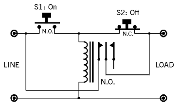 |
|
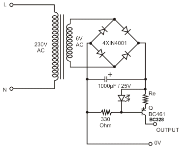
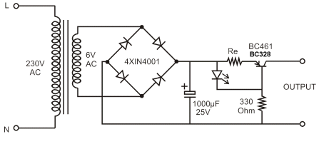
6v and 12v FROM TRANSFORMER It is not a good idea to connect a single diode to the output of a transformer to produce a power supply as this will only take one-half of the energy from the winding (transformer) and the other half of the cycle will create magnetic flux in the core of the transformer that is not removed. When the next cycle is delivered to the transformer the core is already nearly saturated and it will become over-saturated and the transformer will heat up. You need to use a bridge rectifier. Here are 3 circuits. Note the clever design using a centre-tapped 6v - 0v - 6v transformer to produce two outputs. If a transformer is rated at 1A, this is an AC rating and must be de-rated to 707mA for your power supply. This means you only have a total 700mA for the 5v and 12v lines COMBINED. 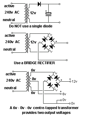 |
|
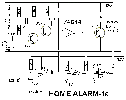
HOME ALARM-1 Here is a Home Alarm using 555 IC's.  The Home Alarm-1 circuit above can be simplified by
using a single 74C14 IC. This IC is also known by the following
numbers:
40106, 40014, and 74HC14. These are CMOS chips and are
characterised by low current consumption, high input impedance and a
supply voltage from 5v to 15v. (Do not substitute 7414 or
74LS14. They are TTL chips and operate on 4.5v to 5.5v and have low
impedance inputs.)
The Home Alarm-1 circuit above can be simplified by
using a single 74C14 IC. This IC is also known by the following
numbers:
40106, 40014, and 74HC14. These are CMOS chips and are
characterised by low current consumption, high input impedance and a
supply voltage from 5v to 15v. (Do not substitute 7414 or
74LS14. They are TTL chips and operate on 4.5v to 5.5v and have low
impedance inputs.)The 74C14 contains 6 Schmitt Trigger gates and 4 of these gates (Schmitt Inverters) are used in this circuit. The circuit consists of a number of "building blocks" and the first consists of two transistors in a very clever "bootstrap" arrangement. The first transistor is turned on via the 3M3 and 47k. The second transistor is not turned on and the output is HIGH. A small signal from the electret microphone will consist of positive and negative excursions and the negative excursion will turn the first transistor OFF. This will turn the second transistor ON and the left lead of the 100n will be pulled towards the 0v rail. The 100n is uncharged and the right lead will also be pulled towards the 0v rail and the input of the 74C14 will see a LOW. This will make the output HIGH and turn on the BC547 transistor. When the second transistor turns ON, it also pulls the 2u2 down and this removes the "turn-on" voltage to the first transistor. The two transistors remain in this state for a few seconds while the 2u2 discharges and the voltage on the base of the first transistor rises. When this happens, the two transistors change state and the 2u2 charges. When the circuit is waiting to detect audio, the 2u2 is charged via the 47k on the base of the first transistor and 47k collector resistor of the second transistor (plus the base-emitter voltage drop of the first transistor). To exit the property, the EXIT button is pressed and this puts a HIGH on pin 1 of the IC so that any signal from the electret mic is not passed to the siren. The EXIT delay is determined by the value of the 100u and 2M2. Normally-open and normally-closed switches will also send a LOW to trigger the siren.
|
|
BENCH POWER SUPPLY Here is a regulated power supply for your bench. The 100n capacitors are needed across the input and output of the regulator IC's to prevent high-frequency instability. The transformer is only 500mA so the maximum you can deliver from the power supply is 300mA TOTAL. 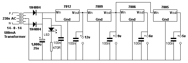 |
|
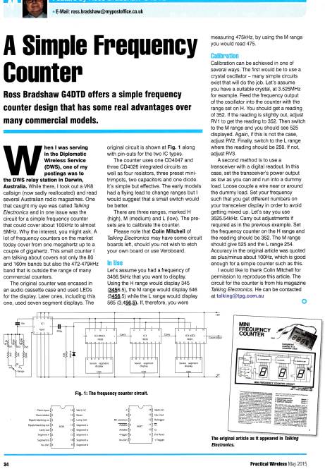
Mini Frequency Counter A kit for this project is available from Talking Electronics. Email Colin Mitchell for details. Click on the project for larger image.
|
|
EM Here is a The circuit |
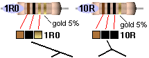 If 3rd band is gold, Divide by 10 If 3rd band is silver, Divide by 100 (to get 0.22ohms etc) 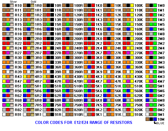 |