|
BEE COUNTER |
|
|
The design for the
project comes from a University research scientist.
Two sets of Infrared photo-detectors were set up so movement from one end of the tube could be counted when the bee returns to the opposite end of the tube. It's a simple flip-flop or toggle requirement.
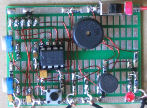
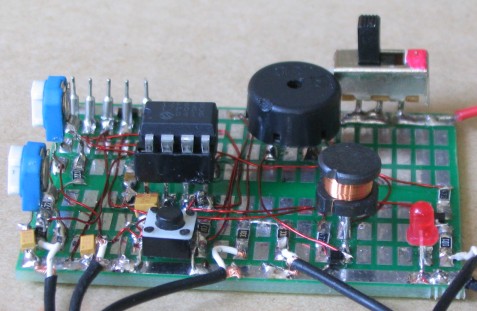
Bee Counter on
experimenter board
Bee
Counter
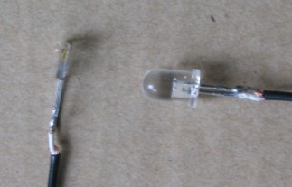
IR
Receiver and IR LED (Transmitter)
|
INSTRUCTIONS FOR USE Set-up the two IR detectors and two IR LEDs (transmitters) so the circuit produces a low-pitched beep when the left detector is interrupted and a high-pitched beep when the right detector is interrupted. |
The CIRCUIT
The circuit is very simple. It is
just 2 IR LEDs, two IR receivers a switch to listen to the count
(low-tone beeps represent 10's and high-pitched beeps represent 1's) and a piezo diaphragm. All the work is done by the micro.
It is powered by 4 AAA cells.
CONSTRUCTION
You can build the circuit on matrix board.
The kit of components comes with all the parts you need to get the
project working, including a pre-programmed chip and the matrix
board.
To modify the program you will need a PICkit-2 programmer and this comes
with 2 CD's containing all the software needed for In-Circuit
Programming.
You will also need a lead (comes with PICkit-2) to connect the programmer to your lap top via
the USB port and an adapter we call 6pin to 5 pin
Adapter to connect
the PICkit-2 to your project.
PROGRAMMING THE
CHIP
The
PROGRAM
Bee Counter
9/1/2012
The kit comes with a pre-programmed PIC chip but if you want to program
your own chip or modify the program, the .hex file is available as well
as the assembly file, so you can see how the program has been written
and view the comments for each line of code.
The PIC12F629 is one of the smallest micros in the range but you will be
surprised how much can be achieved with such a tiny micro.
The program contains sub-routines to produce delays, sequences on the
display and both read and write EEPROM; jobs that require accurate code
- including a special sequence - called a handshaking sequence that
prevents the EEPROM being written due to glitches.
Even a program as simple as this is not easy to put together and to
assist in this area, we have provided a whole raft of support material.
Not only do we provide a number of programs with full documentation but
our approach to programming is simple.
It involves a method of "copy and paste" whereby sub-routines
are taken from previously written code and copied into your program. Any modifications are
made in very small steps so that each can be tested before adding more
code.
This is exactly how we produce a complex project. Each step is written
and tested before adding the next step.
This saves a lot of frustration as it is very easy to add a line
of code that is incorrect and get an unsuspected result.
If you follow our suggestions you will buy a programmer ("burner")
called a PICkit-2 if you are using a laptop. It is the cheapest and best on the market
and comes with
a USB
cable and 2 CD's containing the programs needed to "burn" the chip.
If you are using a desk-top and/or tower with a serial port, you can use
a cheaper programmer called MultiChip Programmer from Talking
Electronics. You
will also need NotePad2 to write your .asm program. This can be
downloaded from Talking Electronics website. You will use
BeeCounter.asm or
BeeCounter-asm.txt as a
basis and it is best to change only a few lines at a time to see what
effect is created. You will also need a 6 pin to 5 pin connector that fits between the burner
and the project. This is also available on Talking Electronics website.
As we said before, this project is for medium-to-advanced programmers as
it is very compact and does not have in-circuit programming pins.
To be able to modify the chip you will need a programming socket and
this can be obtained from one of our other projects that contains the 5
pins for in-circuit programming. Or you can build a programming socket
by adding a socket to a surface-mount PC board and solder 5 pins to one
edge and connect the socket to the pins.
You can then put the chip into the socket and program it.
PROGRAMMING LANGUAGE
There are a number of kits, programs and
courses on the market that claim and suggest they teach PIC Programming.
Most of these modules and courses use a PIC microcontroller as the chip carrying out
the processes, but the actual programming is done by a proprietary
language invented by the designer of the course.
Although these courses are wonderful to get you into "Programming
Microcontrollers" they do not use any of the terms or codes that apply
to the PIC microcontroller family.
All our projects use the 33 instructions that come with the PIC
Microcontroller and these are very easy to learn.
We use the full capability of the micro and our pre-programmed chip is
less than the cost of doing it any other way.
In addition, anything designed via our method can be instantly
transferred to a PIC die and mass produced. And we use all the input
pins and all the memory of the chip. The other approaches
use less than 25% of the capability of the memory and one of the pins is not available.
In fact it would be difficult to reproduce this project via any of the opposition
methods. It would require a larger chip and more expense.
You can use our method or the opposition. Just be aware that the two are
not interchangeable.
Ours is classified as the lowest "form" (level) of programming - commonly called
machine code - invented in the early days of microprocessors - and now
called mnemonic programming as each line of code is made up of
letters of a set of words. The opposition uses a higher level language
where one instruction can carry out an operation similar to a
sub-routine.
But you have to learn the "higher level language" in order to create a
program. And this requires a fair amount of skill and capability.
It sounds great and it is a good idea. But if you want to learn PIC
programming, it does not assist you. It is "a step removed" from
learning PIC language. The other disadvantage of the opposition is the
"overhead." The 1,000 spaces allocated for your program is filled with
pre-written sub-routines. You may require only 10 of these sub-routines but ALL
of them are loaded in the memory space. And they take up all the memory.
You have no room for your own program.
To get around this the opposition uses the 128 bytes in EEPROM to deliver
instructions on how to apply the sub-routines. This provides about 30 powerful instructions using their
language called BASIC (or a similar language).
It's a bit like selling a diary filled with all the paragraphs you need
to express yourself, and leaving a few blank pages at the back for you
to write single lines such as: see page 24, paragraph 7, see page 63
paragraph 4, to create your diary entries.
It depends on how much you want to be in charge of writing a program. Using
our method is like writing your own auto-biography. Using the opposition
is like getting a "ghost writer."
When using a higher level language to create a program, you have absolutely no
idea how the code is generated for the micro.
In some of the developmental kits, the code is "locked away" and you are
NEVER able to access it.
Everything runs smoothly until a fault appears. With our method you can
see the code. With the other methods, you cannot see the code - it's
like doing key-hole surgery without the advantage of an
illuminated endoscope to see what you are doing.
Everything has its place and our method of hand-assembly is only
suitable for very small micros and you will eventually need to "learn a
high level language." The PIC12F629 has over 1,000 locations for code
and this equates to more than 20 pages when printed, so this is about
the limit to doing things by hand.
But our drive is to show how much can be done with the simplest devices
on the market, at the lowest cost.
Anyone can show you high-technology at a high price but this is not
where you start and this is not where you get enthusiasm.
We provide the things to get you started. That's the difference.
The program starts in a loop
to detect when the left IR detector is interrupted. It then goes to a
second loop to detect when the right IR detector is interrupted. When an
IR detector is interrupted, the output goes HIGH. The sensitivity can be adjusted by moving the IR LED closer to the receiver.
A 10k pot is also included to adjust the sensitivity.
When the right IR detector is interrupted, a "count file" is incremented
and a 10mS output is produced via a PNP transistor. A 100R on the output
protects the transistor from any short-circuits.
A LED indicates the output has been sent.
The project keeps a tally of the number of "cycles" and this can be
"read" by pressing the switch.
The count is recorded by listening to low-pitched beeps to represent
10's and high-pitched beeps to represent 1's.
Here are the files you will need:
BeeCounter.asm
BeeCounter-asm.txt
BeeCounter.hex
;*************************************************************
;;Bee Counter.asm
;*************************************************************
;Left IR detects then increments count on right-side detection
;   12F629.asm
;  8-1-2012


	list	p=12F629
	radix	dec
	include	"p12f629.inc"

	errorlevel -302	; Don't complain about BANK 1 registers

	__CONFIG _MCLRE_OFF & _CP_OFF
           & _WDT_OFF & _INTRC_OSC_NOCLKOUT  ;Internal osc.


temp1	  equ 20h	;
temp2	  equ 21h	;
temp3	  equ 22h	;
units	  equ	23h	;
tens	  equ	24h	;
del_x     equ	28h
del_y     equ	29h
tempunits   equ	2Ah
temptens    equ	2Bh

;****************************************************************
;Equates
;****************************************************************
status	equ	0x03
rp1	equ	0x06
rp0	equ	0x05
GPIO 	equ     0x05


status		equ 03h
option_reg	equ 81h


	; bits on GPIO

pin7	equ	0	;GP0  left IR detector - input
pin6	equ	1	;GP1  goes low to produce HIGH signal - output
pin5	equ	2	;GP2  Sw input  sends count to beeper - input
pin4	equ	3	;GP3  right IR detector - input
pin3	equ	4	;GP4  beeper  - output
pin2	equ	5	;GP5


	;bits

rp0	equ	5	;bit 5 of the status register


;****************************************************************
;Beginning of program
;****************************************************************
Start	org	0x00	;reset vector address
	nop
	nop
	nop
	nop	;NOPs to get past reset vector address
	nop
	nop     ;set up to allow counting from external oscillator

SetUp	bsf	status, rp0 	;Bank 1
       	movlw	b'11001001'	;Set TRIS
	movwf	TRISIO
	bcf	status, rp0	;bank 0
	movlw   07h         	;Set up W to turn off Comparator ports
        movwf   CMCON       	;must be placed in bank 0
	clrf 	GPIO       	;Clear GPIO of junk
	clrf	flags
	clrf	units	    	;initialise count = 0
	clrf	tens     	;initialise count = 0
	goto 	Main


;****************************************************************
;* Delays
;****************************************************************


_10mS	movlw	0Ah
	movwf	temp2
D_a	nop
	decfsz  temp1,1
	goto    D_a
	decfsz temp2,1
	goto    D_a
	retlw   00


	;Delay 0.25 sec

D_250mS	movlw 	01h
	movwf 	temp3
DelX	decfsz 	temp1,1
	goto 	DelX
	decfsz 	temp2,1
	goto 	DelX
	decfsz 	temp3,1
	goto 	DelX
	retlw 	00

;****************************
;* Sub-routines		*
;****************************

    ;output produces long beeps for tens
    ;and short beeps for units to signify count.

output	movf	units,0
	movwf   tempunits
	movf	tens,0
	movwf   temptens
	movf	temptens,1   ;check for zero
	btfsc	status,2	;zero flag Will be set if file is zero
	goto    $+4
	call    tensbeep
	decfsz	temptens,1
	goto	$-2
	call	D_250mS
	call	D_250mS
	call	D_250mS
	call	D_250mS
	movf	tempunits,1   ;check for zero
	btfsc	status,2	;zero flag Will be set if file is zero
	retlw	00
	call    unitsbeep
	decfsz	tempunits,1
	goto	$-2
	retlw	00


	;produces "beep" to indicate bee has moved and outputs to output.

shortbeep
	movlw	0ffh
	movwf	del_y
	movlw	.45
	movwf	del_x
	nop
	decfsz	del_x,1
	goto	$-2
	movlw	b'00010000'
	xorwf	gpio,1		;toggle GP4
	decfsz	del_y,1
	goto	$-8
	call	D_250mS
	retlw	00


	;short beep to indicate units

unitsbeep
	movlw	80h
	movwf	del_y
	movlw	.45
	movwf	del_x
	nop
	decfsz	del_x,1
	goto	$-2
	movlw	b'00010000'
	xorwf	gpio,1		;toggle GP4
	decfsz	del_y,1
	goto	$-8
	call	D_250mS
	call	D_250mS
	retlw	00


leftbeep
	movlw	80h
	movwf	del_y
	movlw	.45
	movwf	del_x
	nop
	decfsz	del_x,1
	goto	$-2
	movlw	b'00010000'
	xorwf	gpio,1		;toggle GP4
	decfsz	del_y,1
	goto	$-8
	call	D_250mS
	call	D_250mS
	retlw	00


		;long beep to indicate tens

tensbeep
	movlw	0ffh
	movwf	del_y
	movlw	0ffh
	movwf	del_x
	nop
	decfsz	del_x,1
	goto	$-2
	movlw	b'00010000'
	xorwf	gpio,1		;toggle GP4
	decfsz	del_y,1
	goto	$-8
	call	D_250mS
	call	D_250mS
	retlw	00


rightbeep
	movlw	0ffh
	movwf	del_y
	movlw	0ffh
	movwf	del_x
	nop
	decfsz	del_x,1
	goto	$-2
	movlw	b'00010000'
	xorwf	gpio,1		;toggle GP4
	decfsz	del_y,1
	goto	$-8
	call	D_250mS
	call	D_250mS
	retlw	00


Up	incf	units,1
	movlw	0Ah		;put 10 into w
	xorwf	units,0		;compare units file with 10
	btfss	status,2	;zero flag will be set if units is 10
	retlw	00
	clrf	units
	incf	tens,1
	movlw	0Ah		;put 10 into w
	xorwf	tens,0		;compare units file with 10
	btfss	status,2	;zero flag will be set if tens is 10
	retlw	00
	clrf	tens
	retlw	00


;****************************************************************
;* Main 							*
;****************************************************************


Main	bsf	status, rp0 	;Bank 1
       	movlw	b'11101101'	;switch and IR receivers GP0 GP2 GP3
	movwf	TRISIO
	bcf	status, rp0	;bank 0
	bsf     GPIO,1		;turn off output LED

	call	D_250mS
	btfss	GPIO,2	        ;input will be LOW when sw pressed
	call    output
	nop
	btfss	GPIO,0	        ;input will be HIGH when bee detected
	goto	$-5 		;Left IR not detecting
	call    leftbeep
	call	D_250mS
	btfss	GPIO,2	        ;input will be LOW when sw pressed
	call    output
	nop
	btfss	GPIO,3	        ;input will be HIGH when bee detected
	goto	$-5 		;right IR not detecting
	call    Up		;increment count
	call    rightbeep
	bcf		gpio,1
	call    _10mS
	bsf		gpio,1
	goto	$-18

	end
Parts List
Cost:
au$20.00
plus postage
Kits
are available
2
- 100R
SM resistors
2 - 330R
SM resistors
2 - 1k
SM resistors
3 - 2k2
SM resistors
2 - 4k7
SM resistors
1 - 10k
SM resistor
2 - 10k mini trim pots
1 - 100n SM capacitor
2 - 1u SM electrolytics
2 - 10u SM electrolytics
1 - BC847 SM
transistor
1 - BC857 SM
transistor
1 - 1N4004 SM diode
2 - IR LEDs (supplied in
kit)
2 - IR transistors (supplied
in kit)
1 - 3mm red LED
1 - SPDT mini slide switch
1 - mini tactile switch
1 - 8 pin IC socket
1 - PIC12F629 chip (Bee routine)
1 - piezo diaphragm
1 - 10mH choke
5 - machine pins for
in-circuit-programming
1 - 4 AAA cell battery
holder
1 - 30cm fine enamelled wire
3m fine screened lead
20cm very fine solder
1 - Experimenter PC board