|
Beetle Mk III |
Connect your Guitar to the airwaves
It has a number of features, with a volume control to adjust the input level and a small, neat box to make it easier to attach to a guitar. The volume control is positioned at the end and when turned up fully, the transmitter provides fuzz (distortion).
|
SUMMARY OF |
|
Range: 20 - 50 metres Supply: 3v Current consumption: 7mA Battery life: approx 50 hours Tuning range: 80 -110MHz (by stretching or compressing the oscillator coil) Fine tune by adjusting the air trimmer (5MHz adjustment) Stability: good. Antenna length - 60 cm |
|
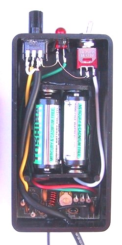
The Beetle Mk III fitted into
a PP12 box. All the |
|
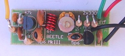
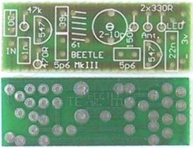
A close-up of the completed PCB |
|
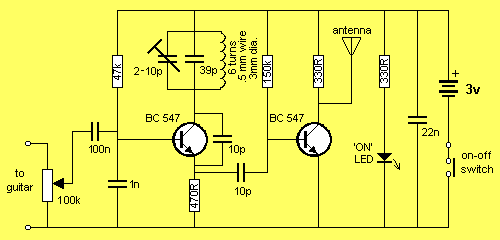
The Beetle MkIII Circuit |
HOW THE CIRCUIT WORKS
The circuit takes the signal from a guitar, radio or tape-recorder and injects it into an oscillator operating at 90MHz. This produces a carrier frequency - also called a Radio Frequency (RF).
This frequency is capable of being radiated to the surroundings and picked up by an FM radio.
But the signal produced by the oscillator stage is not very "powerful" so we pass it to an amplifying stage called a BUFFER or OUTPUT STAGE to increase the amplitude.
We can now connect an antenna to the output stage so the signal can be radiated.
The circuit can also be connected to an acoustic guitar by connecting a conducting microphone to the body of the guitar.
One of the best microphones for this purpose is a piezo diaphragm.
It is attached to the guitar with Blu-Tack and the two leads connected across the 100k input pot. The attenuation (volume control) can be adjusted to give the required signal level.
|
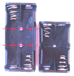
The Beetle MkIII kit also includes a battery holder |
|
PARTS LIST |
|
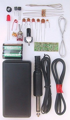
2 - 330R 1 - 470R 1 - 47k 1 - 150k 1 - 100k mini pot with shaft 2 - 10p ceramics 1 - 39p ceramic 1 - 1n ceramic 1 - 22n ceramics 1 - 100n mono-block (monolithic) 1 - Air trimmer 2p-10p 2 - BC 547 transistors 1 - 6 turn coil .5mm enamelled wire 1 - 5mm red LED 1 - LED mount 1 - 6.4mm mono plug 1 - SPDT mini toggle switch 1 - 30cm shielded wire 5 - 10cm hook-up wire 1 - 15cm tinned copper wire 1 - 30cm fine solder 2 - "N" cells 1 - "AAA" cell holder 1 - 60cm antenna wire 1 - PP12 box 1 - BEETLE - Mk III PC BOARD |
|
Beetle MkIII Printed Circuit Board |
|
Due to non-availability of "N"
cell holders in Australia, we have had to include a AAA cell holder into
the Kit, but with the use of a Hax saw the holder can be cut in two
places as shown in the
picture. The middle part is removed and the two ends jointed to become a "N" cell holder. |
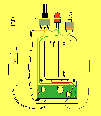
CONSTRUCTION
All the components fit on a PC board 14mm x 35mm. The pot, LED and volume control fit at one end of the box and are connected to the board with short leads.
The position of each component is marked on the PC board and you should have no difficulty constructing the project if you have made some of our other projects.
When all the parts have been fitted, three holes are drilled in one end of the box to take the switch, LED and volume control.
|
Wiring layout for the Beetle MkIII |
SETTING UP
Tune across the FM and select a spot that is free of other transmissions, preferably at the low end of the band.
Switch the project ON and the LED will indicate power is applied.
Adjust the coil by expanding or compressing the turns until the radio goes silent.
This indicates the carrier from the transmitter is being picked up by the radio.
Now move the project away and fine tune the oscillator via the air trimmer to get the transmitter and radio on exactly the same frequency.
Fit the lid to the box and attach it to your guitar with Blu-Tack or Velcro. Insert the 6.4mm plug into the guitar and the project is complete.
Adjust the volume control to get the desired level. The volume can be increased to get a FUZZ effect.
SELECTING THE FREQUENCY
Beetle MkIII is designed to transmit at about 88-92MHz with the 6 turn coil provided in the kit.
This is at the lower end of the commercial (88MHz to 108MHz) band. If you want to transmit below the band (86-88MHz) you will have to either compress the turns of the coil or add one more turn.
The best thing to do is add one more turn (there is enough wire provided in the kit for you to do this) so you can space the 7 turns neatly.
With a 7turn coil you will be able to go to 86MHz and tune the exact frequency you require with the aid of the air trimmer.
You must have a radio or tuner that will pick up the 86MHz band. If you don't, you can detune a radio by turning the trimmer capacitors on the back of the tuning gang so that the radio stations move up the dial and produce a space at the bottom of the band.
If you want to transmit above the commercial band, you can remove one of the turns of the coil and adjust the frequency with the trimmer capacitor. The transmitter may not have the same range at 108MHz as the transistors are operating at their maximum capability and the output power may be less at 108MHz.
IF IT DOESN'T WORK
The first thing to do is remove the 10p capacitor on the base of the output transistor and connect the LED Power Meter to the collector of the oscillator transistor.
At this point in time you should not have anything connected to the input of the project as it may upset the oscillator circuit. Also, the supply must be a set of 2 cells with short leads as anything else will also upset the performance of the circuit.
Turn the project ON and watch the needle on the multimeter. A reading will indicate the oscillator is working. The magnitude of the reading is not important at this stage, all we need to get is a reading.
The short lead to the LED Power Meter will act as an antenna so you can bring an FM radio near the project and tune across the dial to pick up the carrier. This will be detected as clean spot or "dead" spot on the dial. If this is not detected, the problem might be the oscillator is operating below the band. Try spreading the turns of the oscillator coil to raise the frequency.
If no reading is detected on the LED Power Meter, the oscillator section will be faulty. This consists of the oscillator transistor, 6 turn coil, air trimmer and 39p, 470R emitter resistor, 10p feedback capacitor. (make sure you have not removed the wrong 10p capacitor), 1n capacitor on the base, 47k base bias resistor and 22n across the power rails. Remove the output transistor and measure the supply current. It should be about 4 - 6mA.
If you think the trimmer has shorted, remove the coil and measure across the trimmer. Only if the reading is zero ohms, will the trimmer be damaged.
You cannot really measure the base or emitter voltage as any meter probe will act an antenna and draw off energy from the oscillator and prevent it from operating.
All you can do is replace the transistor and the 4 capacitors mentioned previously. Ceramic capacitors can go open circuit during soldering as the leads are soldered to the substrate and
this can crack or melt during soldering or when the component is fitted to the board - it all depends on the quality of the capacitor. If they are not damaged during soldering, they are a very reliable component.
This project has been used by some constructors as the basis of a very successful business, supplying FM transmitters to music groups.
Each transmitter can be tuned to a different frequency and mixed at the console. This gives the players freedom to move around the stage without tripping over wiring and leads.