|
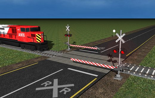
Boom Gates |
|
|
| This project is an "ADD-ON" to
Crossing Sound
MkII. It
controls the
raising and lowering of BOOM GATES. The servo is slowed down to produce a realistic operation. (Crossing Sound and Boom Gates requires 2 micros. Thus the need for 2 PCB's) |
This is a project you will want to add to your layout.
It activates a set of Boom Gates to produce a very realistic effect by
slowing down the output of a servo.
It is added to Crossing Sound project that provides Crossing
Lights and Bell.
detects a train and produces a pulse to alter the points to alternately divert the train to the siding or allow it to travel ahead.
This project
controls the raising and lowering of 2 Boom Gates via two SERVOs.
A SERVO is a motor and gearbox with an output that rotates up to 270
degrees.
By adding an arm (or crank) to the output, we can get linear motion via
a "push-rod" to
change a set of points.
This project does not operate Peco solenoid points or Tortoise Controllers. It
only controls a SERVO.
Don't get confused with a SERVO and STEPPER MOTOR.
A Stepper Motor produces accurate rotation by means of a directly
applied signal to poles (coils) surrounding an armature and by pulsing
the coils in the correct sequence, the armature rotates a few degrees on
each impulse. It has no internal electronics and generally produces
continual rotational movement. A Servo produces up to 270 degrees of
rotation and then it generally reverses direction.
•
• Output to relay to power frog rails
These features are contained in our simple design and can be built in an evening. A kit of components is available from Talking Electronics as well as a pre-programmed microcontroller.
Using a SERVO is the cheapest way to automate a set of points and
produces fully automatic operation for approx. $25.00
A SERVO is the
cheapest way to control a set of Boom Gates.
This project operates the servo slowly to get the effect of a TORTOISE
CONTROLLER with the advantage of placing the servo next to the track so
you don't have to cut a hole in the layout or any other awkward
installation. It is also much cheaper than any other controller.
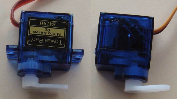
This is one of the servo's we tested. We call it MEDIUM SIZE. The LARGE
servos are too big for this application.
SOUND-BELL-BOOM
GATES
Here is the full circuit for the project. You must build the
SOUND and BELL section first.
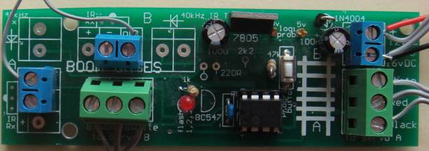
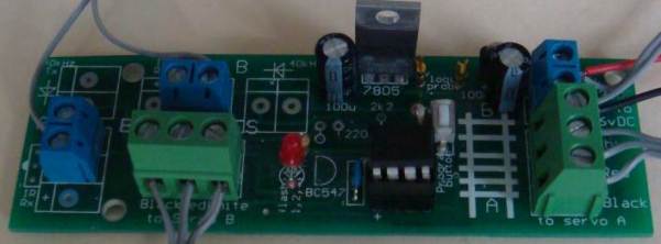
The Boom Gates section is built on the BOOM GATES PC board.
The two infra-red LEDs and two 38kHz receivers are not added to the
board as they are on the Lights and Bell PC board.
Here is a photo of the components added to the BOOM GATES PC board and
the wiring to the sensors.
Only one of the terminals is used on each of the two blue input terminal
blocks.
The Crossing Sound PCB is connected to the Boom Gates PCB with 4 wires as shown in the following diagram:

A very SMALL SERVO uses a micro motor. A Micro Motor is
designed "INSIDE-OUT."
The armature is wound on a former and the turns are GLUED TOGETHER with
resin.
The former is then removed and the armature mounted over a strong
cylindrical magnet that has a North and South pole, with the North on top and South
on the bottom. There are 3 sets of windings, just like a 3-pole motor
and the ends are terminated at 3 copper segments called a commentator.
This commutator can surround the shaft or be located at then end of the
winding. Two brushes touch the commutator segments to deliver current to
the windings.
A coreless motor can produce twice the torque of a conventional motor
because the armature does not have any iron. The iron absorbs magnetic
flux and gets hot.
The armature is also further away from the centre of rotation and this
produces more torque for the applied current.
Micro Motors are also known as PAGER MOTORS, where they come with a
weight connected to one side of the shaft (called an eccentric weight -
not centric). When the shaft rotates, the
motor vibrates (as in a mobile phone).
This type of motor can be produced with a case or body having a very small diameter and a
short overall length and this allows a SMALL servo to be produced.
The servo in the kit is the MEDIUM SIZE and comes with a set of HORNS. These are commonly
called CRANKS or ARMS or LEVERS and connect to the output shaft with a splined connection (grooved) to prevent the arm slipping on the shaft.
Some come with a screw to hold the arm in place.
Make sure you get a SERVO with a bag of horns.
Single Horn or Arm
Star or Cross
Double Horn or Arm
SLOW-MOTION
The secret to making the servo operate slowly is a program in the micro.
It creates a "MARK" (the length of time the control-line is HIGH) that
tells the servo to advance (rotate) the output shaft a few degrees. The
program then creates a Mark to advance the shaft a few more degrees.
This produces a slow, jerky movement, of the output. Each value is
outputted a number of times and this creates the slow motion. You
can use an R/C servo or Linear Actuator.
CONNECTING THE SERVO
Connecting a servo to a boom gates is done using an arm and a
push-rod (pull-rod).
The arm and rod turn the rotary motion of the servo into linear motion
and the distance traveled by the rod is the greatest when the output of
the servo rotates 180°.
The distance is called the
"THROW" and a number of holes on the arm (also called the "CRANK")
selects the throw to suit the distance needed for the Boom Gate.
The arm and rod is called the "LINKAGE" and this needs to be designed so
that the rail sits with a small amount of pressure to keep it in place.
The project is designed to produce about 90
degrees of rotation for the servo. This produces enough "throw" to
fully raise and lower the Boom Gate.
Most servos will rotate up to 180° and some will rotate to nearly 270°. Our project only needs about 90 degrees rotation to produce a THROW of about 14mm when a push-rod is connected to the correct hole.
WIRING THE SERVO
Servos come with different colours on the 3-pin connector:
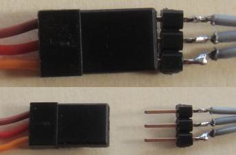
Solder the 3-pin connector in the kit to the 3-wire lead
THE CONTROL LINE
The control line is called the "signal Line" and requires a waveform that is classified as a DIGITAL SIGNAL. This means it must rise to about 5v and down to about 0v to for the circuit inside the servo to respond.
The time when the signal is high is called the MARK and the low time is called the SPACE.
The width of the MARK determines the position of the output and it only takes a few cycles for the servo to respond and drive the motor to the angular location where the received signal matches the signal from the input potentiometer.
The signal on the control line is called PULSE CODED MODULATION and the HIGH will vary from 0.5mS to 2.5mS.
The LOW time needs to b e about 20mS.
This means the coded signal arrives at about 50 cycles per second (50Hz).
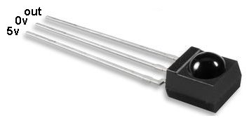
IR RECEIVER
The Infra red receiver is not just a LED or transistor detector. It is an integrated circuit circuit containing a circuit that detects the Infrared light and only output a signal when the frequency is either 36kHz or 38kHz.
There are two different detectors (such as TSOP4136 and TSOP4138) and the numbering refers to the frequency at which they operate.
Our project transmits at 38kHz and the other detector will not work.
TWO MICRO'S
The project needs two micros because two things have to be done
at the same time.
The sound is activated during the time when the boom barriers are
lowered.
Although the servos do not take up the whole of the micro's time when
lowering, it would be very difficult interleaving the mark-space-ratio
for the servo with the sound and lights program.
That's because the servo program consists of 15uS delays and the sound
sub-routine consists of short delays.
Two small micro's are cheaper than one large micro and so we have a
situation of a master-micro and a slave-micro.
The master micro is on the Crossing Sound MkII PC board and since all
the outputs are used, we have to take two control lines from the lights
section and use them as inputs for the Boom Gates PC board.
Normally, only one of the lights is active at a time so we can look for
the first line being LOW and pulse the second line LOW to deliver the
activation signal.
These pulses are so brief that the second LED will flash very quickly
and not be noticed.
MOUNTING THE SERVO'S

The Platelayers packaging
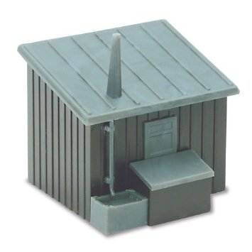
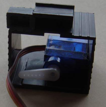
The hut fully built
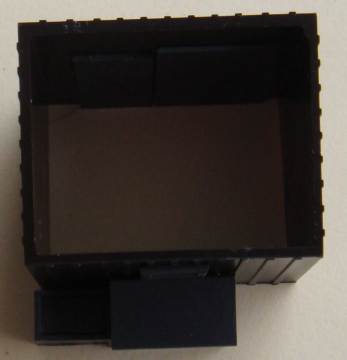
Looking inside the hut
![]()
Place a shim next to the door so the servo can be glued in position
Remove the flanges with side-cutters
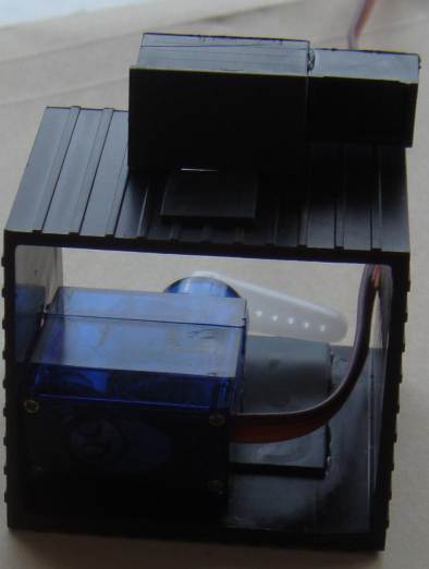
Glue the servo in position so it does not touch the roof.
Cut a slit in the side of the hut for the push-rod and
a wider slit for the wires to the servo.
The arm needs to be 2mm from the ground and
when the push-rod is fitted into the hole on the arm and
the hut placed on the layout, the push-rod
will stay in place.
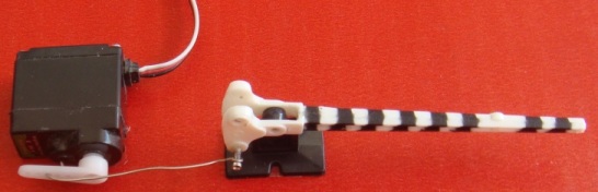
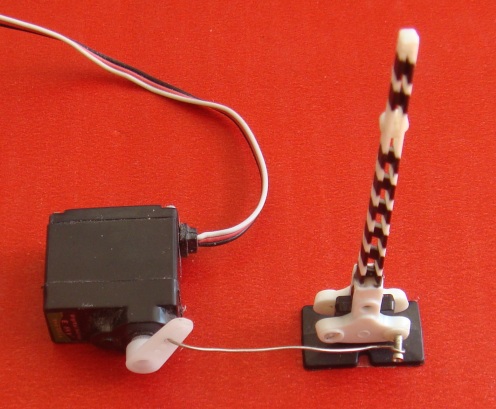
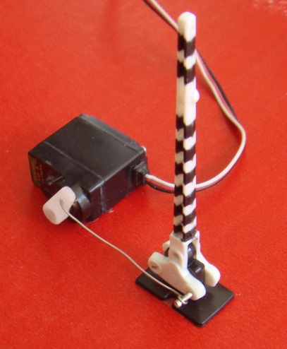
Here are three images to show how the servo is connected to the
boom gate. You will need to press the pin into the plastic arm of
the boom gate by holding it with a pair of snips and heating it up with
a soldering iron so it pushes into the boom gate AND STAYS THERE.
The thick copper wire is included in the kit and will need to be longer
than shown to reach from the Plate Layers hut to the boom gate.
|
|
|
25/6/2016