|
CROSSING SOUND |
|
Kits:
Crossing
Sound MkII
|
|
We also have a kit to detect the presence
of IR from the IR diodes. |
|
We also have a
LED TESTER kit
|
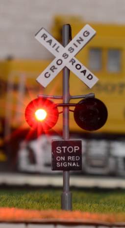
This project is designed for a model railway layout.
It provides flashing lights as well as a boom gate bell-sound.
And it is AUTOMATIC.
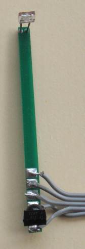
It is activated by an Infrared Beam and receiver IC that has been placed on a small, narrow PC board fitted between the tracks at a distance from the crossing. Another is fitted at the other side of th crossing about 1 -2 metres from the crossing. The front of the train breaks the beam and activates the circuit. A train in either direction will activate the project.
The circuit waits for a beam to be broken and this produces a HIGH on the input to the microcontroller via an "OR" gate in the circuit. The outputs of the IR detectors are LOW when detecting a beam and when a beam is cut, the output goes HIGH. The diodes in the circuit allow this to take place. In other words th circuit is an "active HIGH" OR-gate.
When the loco passes the other beam it is broken by the front of the train and the sound stops.
The project is then reset and is ready for a train in either direction. All this is done by the microcontroller.
Talking Electronics also has a project to operate a set of boom gates via a slow-acting motor and gearbox to give reality to the activation. The project does not have sound. See BOOM GATES project HERE.
TIMING
The project works on TIMING.
The project waits for a beam to be broken and the SOUND AND LIGHTS are
activated.
The project produces LIGHT AND SOUND for 5 seconds and then looks to see
if the full length of the train has passed the beam. LIGHT AND SOUND
continues to be emitted.
The circuit then looks for a second "broken beam" to stop SOUND AND
LIGHTS.
This is how the circuit determines the train has passed from one beam to
the other.
If you stop the train or delay it or run 2 trains in succession, the timing
may not respond correctly.
PRODUCING A TONE
Producing a decaying note with
resonance is not an easy task with a microcontroller. We have produced
the basics of the tone with a program and used two transistor stages to
get the decay.
This results in a ding-ding-ding-ding-ding.
At the same time the two LED flash alternately at a low rate.
We have used IR detectors
because the level of light varies from one layout to another and
sometimes sunlight enters the room.
This changes the ambient light conditions enormously and fluorescent
tubes have an effect on normal light sensing devices.
Adding 38kHz coding to the
Infrared transmission eliminates any interference and makes the project
very reliable.
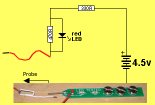
IR DETECTOR KIT
A project is available to detect
the presence of signal from the IR diodes
IR Detector.
You can detect the presence by looking at the diodes with a digital camera,
but this will not let you know if the LED is pulsing at 38kHz.
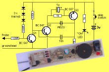
The IR DETECTOR kit has two circuits and by moving the detector
closer to the IR LED, you can see if the emission is bright enough to be
detected by the CROSSING SOUND MkII Project. We don't want the
LED to be too bright as the wrong receiver will pick up the signal. And
we don't want the LED to be too dull or the project will not work.
That's why we have used fairly weak LEDs and put a cover over them to
concentrate the beam to only be picked up by the closest receiver.
FLASHING LEDs
The red LEDs in the kit are low bright as super bright LEDs are too
bright for the plastic model.
The 4 dummy red lens are removed and the 3mm LEDs fit very neatly.
The shorter cathode leads are at the bottom and one anode lead is bent
over to touch the other anode lead.
Both the leads are cut very short and soldered very quickly to prevent them
being damaged.
The two cathode leads are also cut very short.
0.2mm enamelled wire is included in the kit and the end is tinned by
firstly scraping off the enamel or using the iron to burn off the
enamel.
Tin one cathode lead very quickly and solder the wire to it.
Do the same with the other cathode lead.
The third enamel wire is soldered to the middle of the anodes and the
three enamel wires are then taken down the back of the pole and taped
with sticky-tap to hide them from view.
These three wires can be extended to the project with hook-up wire.
The other crossing light is wired exactly the same and the 3 enamel
wires are are joined to the hook-up wire to make a parallel connecting
with the first crossing light.
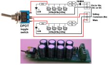
The following two diagrams will help you with the wiring:
Easy-to-understand circuit
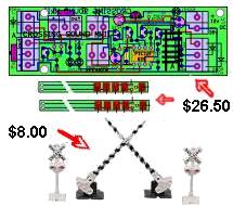
Connecting the sensors to the PC board
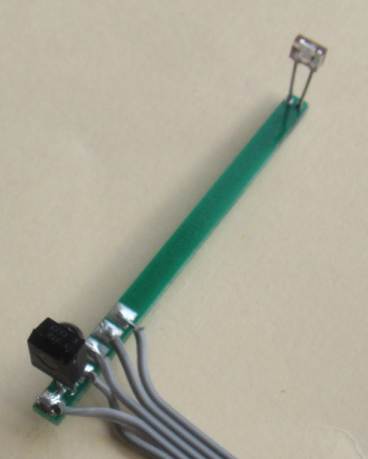
The bottom 2 wires of the flat ribbon cross over.
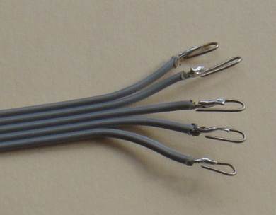
Prepare the ends with tinned copper wire before fitting to terminal
blocks
The bottom 2 wires of the flat ribbon cross over.
CONNECTING THE SENSORS:
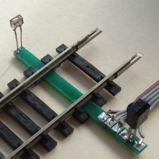
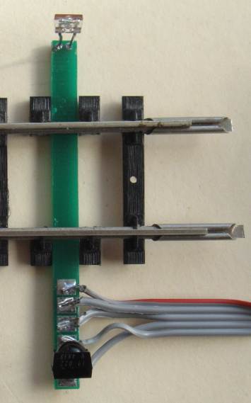
Note: wires 4 and 5 are crossed-over
The kit contains black sleeve. Cut 5mm and glue over the
LED to prevent the signal spreading.
Here is the normal price:
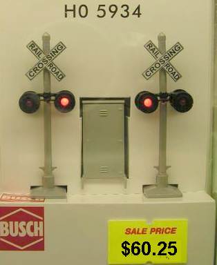
Two Bachmann HO crossing signals are included in the kit
WIRING THE CROSSING SIGNALS LEDs:
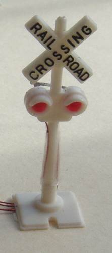

Wiring the 3mm LEDs
BOOM GATES
THE PRINTED
CIRCUIT BOARD:
The kit contains 2 boom gates because
the Crossing Signals from Bachmann comes in a pair with 2 Boom Gates.
You will be able to use the Boom Gates at the same crossing as the
Signals by using Talking Electronics Boom Gates
project.
Solder a short length 0.5mm tinned copper wire to the ends of the
ribbon cable before fitting into the terminal blocks to hold the
wire in place.
It is best to use a DC supply but an AC supply up to 16v can be used
as the single power diode will provide half-wave rectification and
the regulator will just manage to deliver a smooth 5v at 50mA load.
PARTS
LIST |
|
|
2 - 220R 2 - 330R 1 - 1k5 5 - 2k2 1 - 2k7 1 - 22k 1 - 1k mini trim pot (some PCB's will have a pot to adjust the LED brightness) 1 - 100n monoblock 1 - 10u electrolytic 2 - 100u electrolytics 2 - 1N4148 signal diode 1 - 1N4004 power diode 4 - low bright 3mm red LEDs 2 - IR LEDs (transmitters) 2 - V4838 38kHz receivers 5 - BC547 transistors 1 - 78L05 3-terminal regulator (100mA) 1 - PIC12F629 with "Xing" 1 - 8 pin IC socket 2 - component header pins for test points
4 - 2-way terminal block 3 - 3-way terminal block 1 - metre 5-wire flat ribbon 2 - Bachmann Crossing Signals 2 - Bachmann Boom Gates (use in Boom Gates project) 2 - 10cm 0.6mm wire for boom push rod 1cm black sleeve to cover IR Tx LEDs. 3metre 0.2mm enamelled wire (for LEDs on Crossing Signals) 20cm 0.5mm tinned copper wire (for ends of ribbon cable into terminal blocks to make the screw grip the wire) 1 - 8R mini speaker 20cm very fine solder 1 - Crossing Sound MkII PCB 2 - Sensor Connector PCB's |
TEST EQUIPMENT
Talking Electronics has a number of pieces of TEST EQUIPMENT to help in the design and testing of projects.
Of course you can use a multimeter for most of the testing but some of the "tricky" faults need a special piece of equipment.
You may only need a LOGIC PROBE once a month, but the project you are designing will come to a stand-still if you can't locate a problem.
We designed all these projects because we needed them ourselves.
Add one of them to each order you place with Talking Electronics and eventually you will have the whole range.
|
LED TESTER Tests LEDs. $1.50 plus $4.00 post (buy a number of kits and pay only one postage) |
 |
|
CONTINUITY TESTER Only responds to resistance less than 50 ohms. Ideal for digital projects as it tests connections very quickly. $12.50 plus $6.50 post (buy a number of kits and pay only one postage) |
 |
|
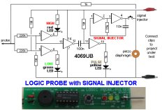
LOGIC PROBE with PULSER
- slimline Detects HIGH and LOW signals on both TTL and CMOS circuits. The piezo allows you to hear low frequency signals and the signal injector (Pulser) will over-ride clock signals to make a circuit operate at a reduced frequency. $8.00 plus $6.50 post |
 |
|
SUPER PROBE 20 different functions. See article for the complete list of functions. $18.00 plus $6.50 post |
 |
|
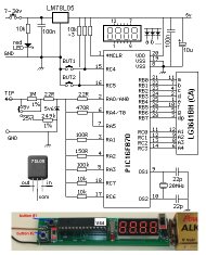
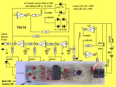
COMBO-2
TRANSISTOR TESTER Tests transistors and shows the gain of the transistor. Also has Signal Injector probe. $21.50 plus $6.50 post |
 |
|
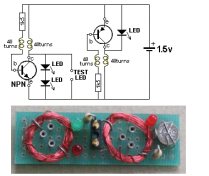
Simple
Transistor and LED Tester - 3 Tests PNP and NPN transistors and LEDs. Also teaches the amazing property of an air-cored coil in producing a high fly-back voltage. $4.00 plus $3.00 postage. (buy a number of kits and pay only one postage) |
 |
|
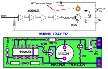
MAINS TRACER Detects 240v AC mains hidden in walls etc. Will also pick up RF signals from a keyboard to show you where Electromagnetic Radiation is coming from and giving you a headache. $10.00 plus $4.50 post |
 |
|
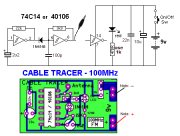
CABLE TRACER
- 100MHz Traces cables when the power is OFF. Uses an FM radio to pickup beeps. $10.00 plus $4.50 postage.
(buy a number of kits and pay |
 |
|
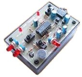
OP-AMP TRAINER and TESTER Teaches how an op-amp works by using pots to control the voltages on the two inputs. $24.50 plus $6.50 post (comes with instructions) |
 |
|
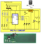
PIC Fx-1 MICRO (8 pin) PROGRAM DEVELOPER and TESTER Learn to program PIC chips. Comes with a pre-programmed PIC12F629 chip with 3 routines. $12.00 plus $6.50 post |
 |
|
model railway
POINT MOTOR CONTROLLER and TESTER
CDU-Inline The cheapest CDU project you can get. $8.50 plus $6.50 post |
 |
1/6/2016