|
LOGIC PROBE |
|
|
We have 2 versions of this project. Version 1 uses one-eighth watt through-hole resistors and version 2 uses surface-mount components.
You can decide which version you want to build and either one will be an experience.
And the boards now have a mechanical buzzer that produces a much-louder output.
These are all improvements and reflect the availability of components.
The project works the same as before. But the piezo diaphragms are hard to get and very expensive.
A LOGIC PROBE is just one piece of equipment to help with designing/testing and diagnosing a project.
And for $9.00 or $8.80 you can't pass it up.
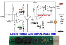
It has two features above other Logic Probes. A pulser to produce a waveform that can be injected into a circuit to produce "clocking" or into audio circuits to determine the relative amplification of a stage. And a mechanical buzzer to hear the presence of waveforms.
You won't be able to listen to very high frequency signals but many signals in a project consist of scanning data and these can be detected as audio.
This project forms part of our overall aim to get you into designing circuits using a microcontroller.
It teaches you how to use a Probe and Pulser and adds to your understanding and analysis of circuits.
You don't need a Logic Probe until a project DOES NOT WORK.
That's when you reach for it.
And it is based on a very simple circuit.
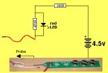
It provides all the features you need and will detect HIGH/LOW voltages on 3v to 15v circuits because the power for the Probe comes from the leads clipped to the power rails of the circuit you are testing.
This provides automatic adjustment for HIGH and LOW values to equate to approx 50% of rail-voltage.
The project also has a Pulse LED to show when a single pulse is detected. This is actually a "pulse extender" and is handy for the time when you are waiting for a single pulse to arrive to activate a circuit.
The piezo also monitors the input and you can hear the activity on the line and compare one line with another.
The PULSER mode delivers a low frequency waveform and this will override some of the waveforms in a circuit to slow-down the activation of a circuit to see what is happening.
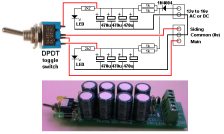
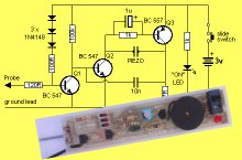
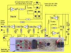
The latest
PCB's use a mechanical buzzer (it contains a transistor
and metal diaphragm and
must be connected to the board around the correct way).
It is
shown in the circuit above and the images below. It is
driven in a very clever
way by a transistor that is AC coupled to the input-line
(from the probe). It takes 1k to
discharge the 100n quickly so the transistor reacts to
the signal.
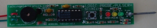
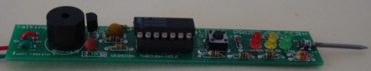
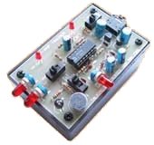
This is the Logic Probe using one-eighth watt
resistors.
It is available as a kit for $8.80. (the cheapest Logic
Probe kit on the market)
No display on the Super Probe MkII project.
The clock pin was injected with the pulser and the Super Probe MkII showed segments on the display at a very low clock-rate to prove the microcontroller was working The problem was one of the 20Mhz crystal leads connected to 0v.
The 8x8 Module did not produce a display. The data and clock lines were probed and it was found the data line was not connected.
The Logic Probe also helped with the input of the Point Controller project to show when the photo transistor changed from LOW to HIGH.
The Logic Probe helped to solve a problem with the Hourglass Timer project. A track was missing !
You don't realise how many times you use a Logic Probe until you keep a list of the incidents.
The illumination of the LEDs on the Logic Probe tell you a lot of things. They show if a line is predominantly HIGH or LOW and the piezo will let you hear the activity on a low-frequency line. This has helped with the display section of the Stroop and NIM projects.
It won't solve all your problems, but it will quickly find open tracks (traces) and let you see the signal on each side of components, such as LEDs, that are not connected to the 0v rail (in a multiplexing or Charlieplexing arrangement).
|
|
|
WHY TWO VERSIONS?
We mentioned to a sales outlet that
we had a new Logic Probe kit and said it used
surface-mount components. He wanted a
through-hole version for beginners.
So we have two versions.
The PC board is very small so we had to use very
small resistors. The project goes together very
easily and if you want to advance to soldering
surface-mount, this is the ideal time to start.
You just need a pair of tweezers and a fine
tipped soldering iron.
Once you try surface-mount you will be hooked.
They are faster to fit and make a much neater
result.
USING THE LOGIC PROBE
Connect the red and black alligator clips to the
project you are testing.
This will automatically allow the Logic Probe to
recognise a HIGH and LOW and a change between
these two values.
It is the voltage-level at which the Logic Probe
changes from HIGH to LOW or LOW to HIGH that is
very important.
It must be very close to 50% of rail voltage.
Suppose you connect the Logic Probe to a 12v
supply and work on a 5v microcontroller project.
When the Probe detects a 5v signal, this will
only be 5/12 = 40% of the input voltage for the
IC on the Probe and it will detect this as a LOW
!
That's why the Probe is always connected to the
project being tested.
Use the probe on lots of working projects to see
how the LEDs illuminate and the piezo responds
to the signals.
This is the only way to find out what to expect.
You must compare your observations with a
circuit diagram as this will be your "library of
resources" for future diagnosis.
When you are working on a faulty project, you
will see the red and orange LEDs brightly lit
and the green LED very dull. This indicates the
line is mainly HIGH.
If the frequency of the pulses are between 50Hz
and 10kHz, you will hear them in the piezo.
USING THE PULSER
The project produces an output waveform of
approx 330Hz when the button is pressed.
This can be injected into a circuit to produce
lots of different effects.
The waveform is called a PULSER, CLOCK,
INJECTOR, OSCILLATOR or SIGNAL INJECTOR,
depending on the type of circuit being analysed
(and how you want to call it).
It is especially handy when trouble-shooting
audio circuits to detect the gain through a
stage. Audio stages are very difficult to
trouble-shoot, especially when three or more
sections are DC coupled. A signal injector
will let you know if a signal is getting through
as some sections are current amplifiers and the
amplitude of the waveform does not increase.
CONSTRUCTION
All the parts fit on a slim-line PC
board with surface-mount components used to
reduce the size and make to the project appear
very simple.
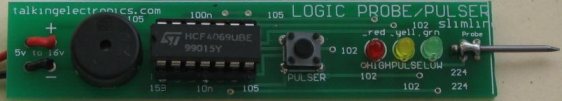
The latest PCB's use a mechanical buzzer as
shown on the two photo's using through-hole
components. The piezo diaphragms became
unavailable.
Two more SM parts are on the new PCB to drive
the mechanical buzzer.
(They are not shown in this version of the PC
board)
All the values of the surface-mount components are identified on the top (silk-screen) and the 10n is the same size as the 100n so don't get them mixed-up.
|
|
|
(buy a number of kits and pay
LED TESTER
Tests LEDs.
$1.50 plus $4.00 post
CONTINUITY TESTER
Only responds
to resistance less than 50 ohms.
Ideal for digital projects as it tests connections
very quickly.
$12.50 plus $6.50 post
(buy a number of kits and pay
only one postage)
LOGIC PROBE with PULSER
- slimline
Detects HIGH and LOW
signals on both TTL and CMOS circuits.
The piezo allows you to hear low frequency signals
and the signal injector (Pulser) will over-ride
clock signals to make a circuit operate at a reduced
frequency.
$9.00 plus $4.50 post for surface mount version
$8.80 plus $4.50 post for through-hole version
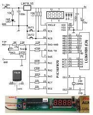
SUPER PROBE
20 different functions.
See article for the complete list of functions.
$18.00 plus $6.50 post
COMBO-2
TRANSISTOR TESTER
Tests transistors and shows the
gain of the transistor.
Also has Signal Injector probe.
$21.50 plus $6.50 post
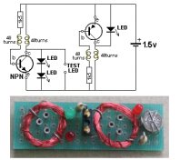
Simple
Transistor and LED Tester - 3
Tests PNP and NPN transistors and LEDs.
Also teaches the amazing property of an air-cored
coil in producing a high fly-back voltage.
$4.00 plus $3.00 postage.
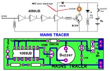
MAINS TRACER
Detects 240v AC mains hidden in walls etc.
Will also pick up RF signals from a keyboard to show you where
Electromagnetic Radiation is coming from and giving you a headache.
$10.00 plus $4.50 post
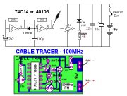
CABLE TRACER
- 100MHz
Traces cables when the power is OFF.
Uses an FM radio to pickup beeps.
$10.00 plus $4.50 postage.
only one postage)
OP-AMP TRAINER and TESTER
Teaches how an op-amp works by using pots to control
the voltages on the two inputs.
$24.50 plus $6.50 post
(comes with instructions)
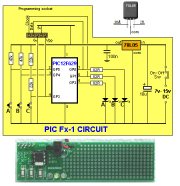
PIC Fx-1 MICRO (8 pin) PROGRAM DEVELOPER and TESTER
Learn to program PIC chips.
Comes with a pre-programmed PIC12F629 chip with 3 routines.
$12.00 plus $6.50 post
model railway
POINT MOTOR CONTROLLER and TESTER
CDU-Inline
The cheapest CDU project you can get.
$8.50 plus $6.50 post