|
WIRING |
The first thing you will do
as an electrician is WIRING. Running the cables for power and light -
often called "roughing-in."
This involves pulling cables through holes drilled in the studs and
noggins of a
partially completed house.
The brackets for the switches and power points are firstly nailed to the
studs at 500mm for power points and 1,000mm for wall and architrave
switches
It's easy to tell the 6-amp lighting cable from the 10-amp power cable.
These cables are commonly called lighting cable and power cable.
Lighting cable is 1.5mm and power cable is 2.5mm This is actually
circular mills but we will not be involved with the complexity of
actually measuring the cable.
Australian cables will handle much more current than the ratings above,
but the regulations specify almost no temperature-rise when maximum
current is flowing and this means the cables will never get stressed,
even when positioned in the roof-space on a very hot day.
You can also purchase 15-amp power points that take plugs (plug-tops)
with a large earth pin. These need to be wired with 4mm cable.
The lighting cable has conductors (active and neutral) with a cross-sectional area of 1sq mm
(for each conductor) and the power cable has a cross-sectional area of
2.5mm (for each conductor).
These cables will handle much more than 6-amps and 15 amps as the
upgrading was done about 20 year ago when a limit of 12 to 15 power points per
run was increased to an open quantity.
However no run will deliver more than about 16 to 20 amps as each is now
terminated by a 16 amp circuit breaker for power and 10 amps for
lighting.
Houses need a separate run to the oven (if electric), the
kitchen and the laundry. These can all be 2.5mm cable. The oven needs to
be 2400 watts maximum for a "10-amp" cable.
The remainder of the house can have one run to the rest of the rooms
downstairs and one run the the all rooms upstairs.
Air-conditioners need a separate run to each unit.
Make sure every "power" device is less than 2,400 watts. This allows the
standard "10-amp" cable to be used (2.5mm). (Ovens, heaters,
tumble-dryers, air-conditioner, welders, etc)
Both the lighting and power cables are "flat cables" and are commonly called
twin and earth.
They are also called TPS cables, referring to Thermoplastic Sheathed
Cable or PVC plastic sheathing. This is also referred to "Tough Plastic
Sheathed."
The Active is always red, the Neutral is black and the Earth is green or
yellow/green striped. Earth is always in the centre.
Active is called LIVE in some countries or HOT.
Neutral is always called Neutral.
Earth is sometimes called GROUND.
Some oven cables use the new standard:
Brown - Red = Live
Blue - Black = Neutral
Yellow/green = Earth
If you can't remember the new colour-coding, try this: When you
get cold you go BLUE WITH THE COLD. Cold = Neutral
Neutral = black Blue = Black
Lighting cable is 1.5mm - twin and
earth approx $65 per 100m
Power cable is 2.5mm - twin and earth approx $100 per 100m
4mm Power cable - twin and earth approx $230 to $260 per
100m
Appliances over 2,400 watts require 4mm cable. This cable can supply up
to 32 amps.
(you have to spend $230 to make a single run - for 100m roll).
Some wholesalers will sell 4mm cable by the metre.
WIRING A HOUSE -
called "Roughing-in."
Two different-sized cables are used to wire a house.
The smaller-size is commonly called 6-amp LIGHTING and
the thicker cable is commonly called 10-amp POWER
Each "circuit" is commonly called a RUN and is terminated at the FUSE
BOX with a CIRCUIT BREAKER.
A small dwelling will require 1 lighting circuit and 1 power circuit.
A wall oven will require a separate circuit.
It is advisable to provide a separate run to the KITCHEN and
1 run to the LAUNDRY.
For larger dwellings add:
1 power-run to UPSTAIRS and
1 lighting-run to UPSTAIRS.
Plus
1 run to each air conditioner
If you know bedrooms will use fan-radiators, allow a separate run to
each bedroom.
Fortunately, cable-colours are RED, BLACK and GREEN/YELLOW.
However cables from a wall oven are BROWN, BLUE and GREEN/YELLOW and
must be connected inside a JUNCTION BOX using 3 x 30amp double-screw
connectors.
Use the following diagram to match the colours:
IDENTIFYING THE CABLES
It is essential to produce a wiring diagram
either before or during the time when running the cables.
On top of this you MUST identify each of the cables at EVERY
switch-point.
Generally, you will have "Active-IN," "Active-OUT" and "Switched."
Mark "Active-IN" with a marker pen with "A" at a point about 150mm from
the end.
Mark the switched wire by nipping a small portion of the sheath with the
pliers at about 150mm.
The other cable is obviously "Active-OUT."
"POWER"
runs - to power points
SCREW CONNECTORS
In most cases, the wiring at a SWITCH POINT
will consist of:
will consist of:
Start each run at the fuse box and drill 20mm holes in the studs with a
spade-bit or auger drill. An auger drill has a spiral to remove the
shavings from the hole.
It is best to run the cable along the top-plate of a a stud wall and drop
it down at the
location above the power-point, as this makes it easy to trace and replace
the cable if a fault occurs as you are not trying to pull it through
holes in the studs.
Terminate the wires though the bracket, leaving at least 300mm for easy
connection.
Continue the run by pulling the cable through a new
set of holes to the next location.
Terminate the cable with a 300mm "tail" and wrap the two ends together
with tape.
Do this with each "loop" and make a plan of what you have done in case
one or more of the wires cannot be found after the plastering.
To save cable, drill though the studs at 600mm from one outlet to the
next and run the cable inside the stud wall at 600mm.
Before each sheet of plaster is fitted, the position of the wiring should be noted
and a hole cut in the sheet and the wires pulled through by the
plasterer.
If this is not done, you will have to refer to your wiring diagram
and/or use one of our cable detectors. See
Fronitce Page for details of
these projects.
FITTING OFF
- connecting the switches,
power points etc to the cables
Fitting-off involves connecting
the switch mechanisms, power points, fluorescent light fittings, smoke
alarms and bayonet (ceiling) fittings after the plaster has been
completed.
Another section covers locating the wires and now you need to learn the
art of preparing the wires for insertion into the various terminals.
All the wires are stranded and this makes it easy to twist two or more
together and put them into a screw-terminal.
STRIPPING -
the art of removing the insulation
There are various methods of removing the PVC sheath.
It is very soft and easy to "tear up the middle" as the grooves in the
side of the cable allow this to be done.
Don't remove any more sheath than you have to, as the max allowable
exposure of
the coloured wires is 35mm for light fittings and 75mm for power points.
You can bite the end of the cable with pliers and remove a small
piece. This will allow you to tear open the sheath (along one of the
side-grooves) to about 100mm.
Or you can use a "Stanley knife" (box cutter) to cut lightly along the
groove on the side of the cable and this will allow you to open up the
cable to 100mm. Remove the sheath completely by folding-over and cutting
with a box cutter or the side-cutter section of your pliers.
The insulation on each conductor can be removed by putting the wire in
the SIDE CUTTER section of the pliers and biting down until the pliers
just hold the wire. By pulling the wire, the end will be removed. This
is called STRIPPING. If you
bite-down too hard, you will cut the wires. If you don't bite down
hard-enough the wire will simply "pull-through" the cutters and not get
stripped.
If you find this difficult to do, you can get another pair of pointed
nose pliers and hold the cable with them and lever your side-cutting
pliers against the long nose pliers to remove the end of the wire.
Make sure you do not cut any of the strands.
You can also use WIRE STRIPPERS. Make sure they are set correctly for
the size of wire you are stripping, so the strands of wire are not cut.
The actual length of the bare copper wires will depend on the terminal
you are connecting to.
Some terminals will only allow direct insertion and you have to work out the
length of the copper to expose by looking at how much wire is in the jaws of the
pliers and how much protrudes from the side of the pliers.
This is your gauge for direct insertion.
If two or more wires are to be twisted together, add a small extra
length, because the length of the copper wire will be reduced due to
twisting two wires together..
If a single wire is to be inserted into a light fitting or power point,
the strands are to be twisted together by holding the pliers on the end
of the strands and rotating the pliers. You will need to do this 4 to 6
times.
Then grip the pliers at about half-way up the copper and bend to 90
degrees. Then get the side of the pliers and bend the end over another
90 degrees.
Squash the wires together so that no strands are protruding.
It is VERY IMPORTANT that no strands are left "floating" outside the
connection.
After finishing the connection, you should not be able to see ANY of the
copper wires.
This is what makes you a perfectionist.
The connection must be TIGHT, NEAT, CLEAN and TIDY.
You cannot allow and of the copper wires to be seen where they enter the
terminal. You MUST NOT cut the insulation and expose the wire at any point along
the cable.
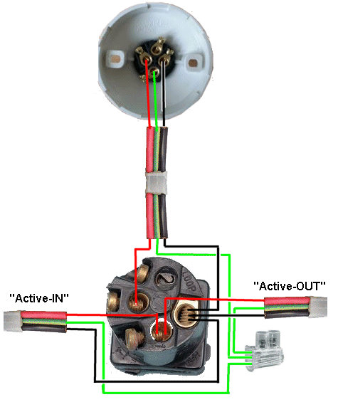
When wiring a switch mechanism, you will be able to connect the
"Neutral-IN" and "Neutral-OUT" to the LOOP terminal on the switch.
You can solder and tape the earth wires but it is quicker to fit them
into a 30-amp connector.
The connector must then be taped to the cables, before screwing
the switch-plate to the wall bracket.
Any wires that are not screwed into a
switch mechanism are joined (connected) via the
"loop" terminal on a switch mechanism.
When more than two wires need to be connected, you MUST use a screw
connector.
The most suitable connector is called a DOUBLE-SCREW 30 AMP OR 40 AMP
CONNECTOR. See image: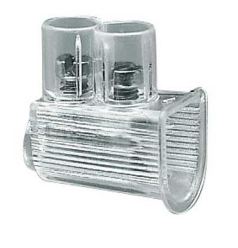
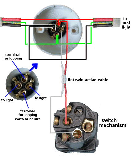
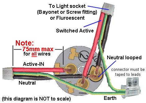
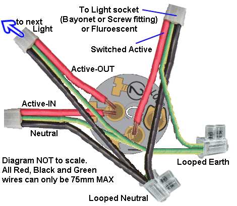
6-AMP cable entering the SWITCH POINT containing ACTIVE-IN, NEUTRAL and
EARTH.
6-AMP cable exiting the SWITCH POINT - called ACTIVE OUT or LOOP to next
switch point.
6-AMP cable exiting the SWITCH POINT to the light fitting - containing
"Switched Active", NEUTRAL and EARTH.
This will require 2 x 30amp screw connectors for the "loop wiring"
(looped Neutral and looped earth).
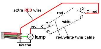
LIGHTING - Method 1: loop
at light
There are two ways to run the lighting wiring.
The first method uses the loop terminal at the light.
This method uses less wire, plus the cheaper red/white "Intermediate"
cable.
(called loops through the ceiling)
with twin red/white
cable to each switch
LIGHTING - Method 2: loop at switch:
The lighting cable loops from one
switch to the next
with lighting cable to each light
MORE LIGHTING information:
Each light is controlled by a
switch, commonly known as a SWITCH MECHANISM. These click into a SWITCH
PLATE so the "10A" cannot be seen.
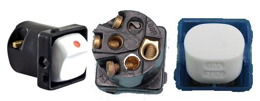
The switch mechanism sometimes has a red dot on top of the rocker.
All
mechanisms have 10Amp printed on the bottom.
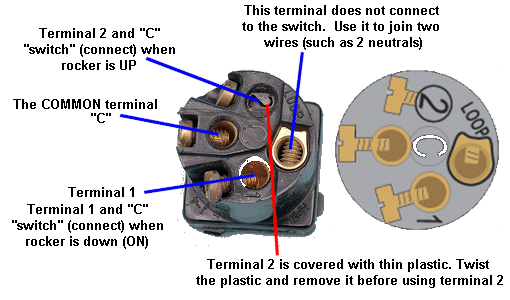
The SWITCH MECHANISM is actually a SINGLE
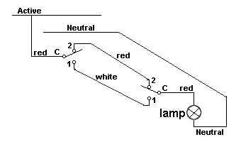
POLE CHANGE-OVER SWITCH, shown in the diagram below:
Wiring diagram for switch and
batten holder
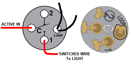
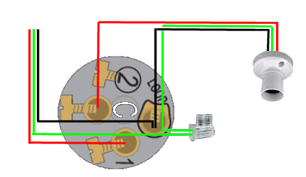
Normally, a switch will be wired in a LOOP SITUATION where the lighting cable will enter the SWITCH-POINT as ACTIVE-IN and will exit as ACTIVE-OUT. Another lighting cable will exit as SWITCHED-ACTIVE to the light fitting. Here is the wiring for LOOP SITUATION:
Wiring a BATTEN HOLDER
(globe holder)
LIGHTING -
two-way switching
Wiring a switch
mechanism (LOOP SITUATION)
Note the comments in the diagram above - 75mm leads MAX and
connectors must be taped to wiring before placing in wall cavity.
A Batten Holder fits to a ceiling to hold a
globe. The globe can screw-in (called ES - Edison Screw) or "Click-In -
called BC - Bayonet Connection or Bayonet Cap.
The earth wire must go into the terminal marked "E", even though it does not
connect to any part of the globe.
The TPS sheathing (the white PVC outer sheathing) must be removed to
allow a maximum of 35mm for the red, black and earth wires.
Unscrew the 4 screws and you will see through 2 of holes while the other
terminals align with the pins connecting to the globe. The pins to the
globe can be wired as Active or Neutral, depending on the way the cable
is fitted. ;
Here is the Batten Holder wiring: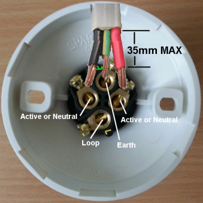
The first thing you have to
remember is the circuit for two-way switching.
Two-way switching allows a light to be turned ON via two different
switches. The position of the rocker on the switch does not represent ON
of OFF as the other switch may have turned the light ON. turned the light ON.
Here is the circuit:
Remember this:
The power (the active) comes from the first switch.
Connect the first switch to the second via red/white cable.
The Common terminal of the second switch goes to the light and the
Neutral goes to the light. 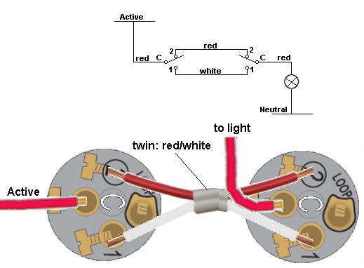
CONNECTING TO THE SWITCH MECHANISMS
SPECIAL NOTE:
The STAIR LIGHT can be controlled from the downstairs circuit:
THREE-WAY SWITCHING
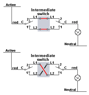
The intermediate switch action:
The Intermediate switch has numbers: 1,1,2,2 or letters:L1, L1,
L2, L2.
2/5/2014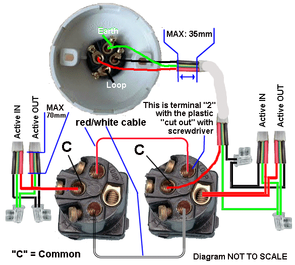
TWO-WAY WIRING
At the first switch, active-IN and Active-OUT are joined and only the active
wire is needed.
Red/white cable is taken to the second switch.
At the second switch, the switch-wire is picked-up from "C" and
the Neutral, plus earth is taken to the batten holder.
When wiring a TWO-WAY on stairs, one of the switches will be downstairs
and one switch will be upstairs.
A double-storey house will have two lighting circuits, one for
DOWNSTAIRS and one for UPSTAIRS.
These will be on two separate RCD's (Residual Current Detectors) and the
stair-light MUST be connected to either the upstairs lighting circuit or
downstairs lighting circuit.
As you can see in the diagram above, it looks like you can take
the active from up-stairs and the neutral from downstairs.
But this will cause both the upstairs RCD to trip and the downstairs RCD
to trip as the upstairs RCD will see current in the active line and NO
CURRENT in the neutral. The downstairs RCD will see current in the
neutral and NO CURRENT in the active.
You must take the NEUTRAL from upstairs to downstairs as shown in the
following diagram:
note: All the circuit (the power) for the STAIR LIGHT is taken from the
upstairs WIRING.
The downstairs wiring is NOT touched.
All the circuit (the power) for the STAIR LIGHT is taken from the
downstairs WIRING.
The upstairs wiring is NOT touched.
Three-way switching is just an extension of two-way switching with an
INTERMEDIATE SWITCH in the middle.
The intermediate switch is an expensive item ($25.00 each at local
electrical wholesalers) or $8.00 on eBay (plus postage).
The Intermediate switch is placed in the middle of a TWO-WAY CIRCUIT: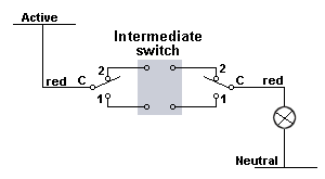
The INTERMEDIATE SWITCH has 4 terminals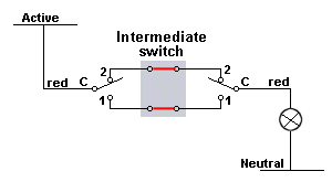
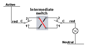
All the numbering and lettering can be confusing.
Get out your multimeter set to low ohms and hold the switch so
the action of the switch is EXACTLY as shown in the diagrams
above.
The switch will have to be turned 90 degrees when fitting into the
switch plate so the rocker action is correct.
Nothing will be damaged if you make a mistake as only the active line is
used for ALL the connections.
Here are the diagrams for intermediate switches marked with L1, L1, L2,
L2 and 1, 2, 3, 4: