|
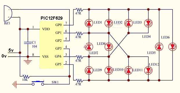
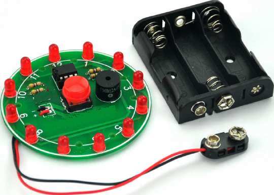
12 LED WHEEL |
|
|
This is a project from a reader. It is available on the web for $10.00 but you have to spend $30.00 minimum.
There is a lot to learn from this program. It is not easy to follow
because it does not have any structure.
1/9/2025
I have included the program so you can see how a reader has used his skill.
The arrangement of the
LEDs is called CHARLIEPLEXING.
The buzzer is an active buzzer that buzzes when connected to 5v supply.
see more discussion below.
Here are the files you will need:
12Wheel.asm
12Wheel.txt
12Wheel.hex
	12 LED Wheel
;
;PIC12F629
;*************************************

	list	p=12f629
	radix	dec
	include	"p12f629.inc"

	;__CONFIG
  ;_MCLRE_OFF & _CP_OFF & _WDT_OFF & _INTRC_OSC_NOCLKOUT  ;Internal osc.

 __config b'0000000111010100'

;*********General Purpose Registers***************

	cblock 20h
key_flag
key_delay_time
add1
add2
wait_flag
buzz_flag
buzz_time_count
time_count1
time_count2
random_data
random_data_buff
random_stop_flag
out_time_data_buff
out_data_buff
run_count
run_count_1
led_on_count
time_1ms_data_reg1
delay_1ms_flag
temp1
temp2
	endc
;***********I/O FUNCTION SET ****************
#define SET_SW GPIO,03
#define BUZZ GPIO,02
;*************TIME DATA SET ******************
#define BUZZ_TIME_DATA .5    ;determines shortness of the beep
#define KEY_LONG_PAUSE_TIME .20
#define key_delay_time_DATA  .39 ;no difference when changed

;*********** PROGRAM START *************
	ORG 000

	goto MAIN

;****************************************************
IO_directing

	movf add1,0
	addwf PCL,1
	NOP
	retlw B'00111000' ;LED1
	retlw B'00111000' ;LED2
	retlw B'00101010' ;LED3
	retlw B'00101010' ;LED4
	retlw B'00011010' ;LED5
	retlw B'00011010' ;LED6
	retlw B'00101001' ;LED7
	retlw B'00101001' ;LED8
	retlw B'00001011' ;LED9
	retlw B'00001011' ;LED10
	retlw B'00011001' ;LED11
	retlw B'00011001' ;LED12
LED_OUT_DATA

	movf add1,0
	addwf PCL,1
	NOP
	retlw B'00000110' ;LED1 ON
	retlw B'00000101' ;LED2 ON
	retlw B'00010100' ;LED3 ON
	retlw B'00000101' ;LED4 ON
	retlw B'00100100' ;LED5 ON
	retlw B'00000101' ;LED6 ON
	retlw B'00010100' ;LED7 ON
	retlw B'00000110' ;LED8 ON
	retlw B'00100100' ;LED9 ON
	retlw B'00010100' ;LED10 ON
	retlw B'00100100' ;LED11 ON
	retlw B'00000110' ;LED12 ON

LED_ON_TIME_DATA
;these values increase the LED ON-time and make the
"wheel" slower and slower. However the beep is the
same length.
	movf add2,0
	addwf PCL,1
	NOP
	dt .6,.6,.6,.6,.6,.6,.6,.6,.6,.6,.6,.6
	dt .7,.7,.7,.7,.7,.7,.7,.7,.7,.7,.7,.7
	dt .8,.8,.8,.8,.8,.8,.8,.8,.8,.8,.8,.8
	dt .10,.10,.10,.10,.10,.10,.10,.10,.10,.10,.10,.10
	dt .11,.11,.12,.12,.12,.13,.13,.13,.14,.14,.15,.16
	dt .17,.19,.21,.23,.25,.27,.29,.30,.31,.32,.33,.34

;*********************************************
MAIN
        NOP
	movlw B'00111111' ;make all pins input
	tris GPIO
	clrf GPIO   ;make all pins LOW  One LED will illuminate
	clrf key_flag
	clrf add1
	clrf add2
	movlw .12
	movwf add1
	movwf random_data
	movwf led_on_count

	;goto KEYSCAN

	bsf wait_flag,0
	bsf random_stop_flag,0
	bsf buzz_flag,0
	bsf buzz_flag,1
	bsf delay_1ms_flag,0

;**********KEYSCAN*********************
KEYSCAN

	btfss key_flag,0
	goto K1
	btfss SET_SW  ;skip if button not pressed
	goto $+3
	clrf key_flag
	goto OUTPUT1
	btfsc key_flag,3
	goto OUTPUT1
	movf add2,0
	xorlw KEY_LONG_PAUSE_TIME
	btfss STATUS,Z
	goto OUTPUT1
	clrf add2
	bsf key_flag,3
	goto OUTPUT1 ;
K1      btfsc SET_SW   ;skip if button pressed
	goto OUTPUT1
	btfsc key_flag,1
	goto $+4
	bsf key_flag,1
	movlw key_delay_time_DATA
	movwf key_delay_time
K2
	btfss delay_1ms_flag,0
	goto OUTPUT1
	decfsz key_delay_time,1
	goto OUTPUT1
	btfss SET_SW  ;skip if button not pressed
	goto K3
	clrf key_flag
	goto OUTPUT1
K3      bsf key_flag,0
	bsf key_flag,2
	clrf random_data
	clrf add2
	clrf run_count
	clrf run_count_1
	bcf random_stop_flag,0
	bcf wait_flag,0
	movf led_on_count,0
	xorlw .12
	btfss STATUS,Z
	goto $+4
	movlw 1
	movwf led_on_count
	goto $+2
	incf led_on_count,1

;********LED SCAN OUTPUT**************

OUTPUT1

	btfss delay_1ms_flag,0
	goto tim_1

;****led stop random data generator***

	incf random_data_buff,1
	movf random_data_buff,0
	xorlw .13
	btfss STATUS,Z
	goto $+3
	movlw 1
	movwf random_data_buff

;****LED SCAN DISPLAY*****************

	movlw 0FFH
	movwf GPIO
	call IO_directing
	tris GPIO
	movlw 0FFH
	movwf GPIO
	call LED_OUT_DATA
	movwf out_data_buff
	movf add1,0
	xorwf led_on_count,0
	btfsc STATUS,Z
	goto OUT2
	btfss buzz_flag,1
	goto $+4
	movlw B'00000100' ;this is buzzer output pin
	movwf GPIO
	goto $+3
	movlw B'00000000' ;turn ON buzzer
	movwf GPIO
	goto OUT3
OUT2    movf out_data_buff,0
	movwf GPIO
	btfsc buzz_flag,1
	goto OUT3
	bcf out_data_buff,2H
	movf out_data_buff,0
	movwf GPIO
OUT3    btfsc buzz_flag,0
	goto $+4
	bsf buzz_flag,0
	movlw BUZZ_TIME_DATA
	movwf buzz_time_count
	btfsc random_stop_flag,0
	goto $+2
	goto $+.10
	movf add1,0
	xorwf random_data,0
	btfss STATUS,Z
	goto $+.6
	movf led_on_count,0
	xorwf random_data,0
	btfss STATUS,Z
	goto $+2
	bsf wait_flag,0
        bcf delay_1ms_flag,0

;************1ms TIMER *************************


tim_1 	movlw	01h
	movwf	temp2
	nop
	decfsz 	temp1,f
	goto 	$-2
	decfsz 	temp2,f
	goto 	$-4
	bsf    delay_1ms_flag,0

;****************************************************

	incf run_count_1,1
	incf add1,1
	movlw .12   ;counts the 12 LEDs
	subwf add1,0
	btfsc STATUS,Z
	goto $+5
	btfss STATUS,C
	goto $+3
	movlw 1
	movwf add1
	movlw 8  ;speed of circling
	xorwf run_count_1,0
	btfss STATUS,Z
	goto KEYSCAN
	clrf run_count_1

;**********BUZZ OFF ***************************

	btfsc buzz_flag,1
	goto $+6
	decfsz buzz_time_count,1
	goto $+4
	bsf BUZZ  ;make pin2 HIGH = turn off buzzer
	bsf buzz_flag,1
	clrf buzz_time_count
        btfsc wait_flag,0
	goto KEYSCAN
	incf run_count,1
	call LED_ON_TIME_DATA
	xorwf run_count,0
	btfss STATUS,Z
	goto KEYSCAN
	clrf run_count
	clrf buzz_flag
	incf add2,1
	movf led_on_count,0
	xorlw .12  ;counts the 12 LEDs
	btfss STATUS,Z
	goto $+4
	movlw 1
	movwf led_on_count
	goto $+2
	incf led_on_count,1
	btfsc random_stop_flag,0
	goto KEYSCAN
	btfss key_flag,2H
	goto $+7
	movf add2,0
	xorlw .10   ;no effect
	btfss STATUS,Z
	goto KEYSCAN
	clrf add2
	goto KEYSCAN
	movf add2,0
	xorlw .60  ;max number of cycles  cannot be .65
	btfss STATUS,Z
	goto $+4
	movf random_data_buff,0
	movwf random_data
	bsf random_stop_flag,0

	goto KEYSCAN

	END
All the programs l produce have everything laid out in a particular
sequence so you know where all the sub-routines will be found in the
program. And each instruction is fully documented.
Each sub-routine performs a tiny operation and they are CALLed from the
main part of the program.
There are only two CALL instructions in this program and one goes to a
data table. This is a set of values and rather than write a line for
each value, with a retlw, the line can consist of 20 or more values.
This saves time and space. You can access any value at any time and it
is very convenient.
The main reason l have included this project is to show different
thinking and new ways to produce a program.
And this is the way to learn new skills.
Produce a prototype, as l have done, and go through the program from the
start and change the value of an instruction and see what happens. Give
each alteration a new file-name so you are sure you will not be re-burnt
as an
old version.
This way you can go back to an older version if things don’t work.
This way you can see what each section does and what each instruction
does, and you will remember it for
later, in a future project.
I have changed, removed and simplified the program to get it to this
stage and the next thing to do is create sub-routines so you can use
them later.
This will involve changing instructions to CALL, instead of GOTO.
You can change the program to make the LEDs cycle in the opposite direction
or turn them on randomly. This adds to your understanding.
I use all this understanding to produce other counting and display
projects including driving stepper motors, operating servo motors very
slowly and creating a speed display for model trains.
Of course you can use a higher-level language to produce the code but
the frustration comes when things don’t work.
I prefer to be in charge and do things slowly and simply and without
frustration.
Designing, manufacturing and inventing need to be a pleasurable
operation, as with designing Printed Circuit Boards and l still use the
first CAD package to be produced, some 50 years ago.
At the end of the day, they get the job done and nothing else was
available when the PIC chip first came out. It was a one-time
programmable chip and you had to use a very expensive erasable version
to produce the program. It was UV erasable with a glass window on top
and took 10 minutes or more to erase. You needed 5 or 10 of these chips
while you were developing a program and even then, you ran out of chips.
The aim is to be able to do everything yourself.
The most difficult part is completing a project. . . .. fixing mistakes and
getting it finished.
If you are reliant on programs that you don’t understand, chances are
you will be stuck at the end.
That’s why learning via our method is so important. It is simple and
relaible.