|
SURFACE MOUNT |
This page describes a PC board for a Surface Mount PIC12F629 with an In-Circuit Programming socket.
For more on soldering and using prototype boards, see the article: Prototyping.
For videos on soldering Surface Mount devices start HERE and see the site for lots more videos.
The board contains a number of LEDs and components so a simple program can be produced and tested. You can add more components if required.
The circuit to program the chip is shown below:
The programming socket is connected to 5 pins of the chip. Three pins, 2, 3 and 5 have been used as output pins for LEDs and a small piezo, for the experiments.
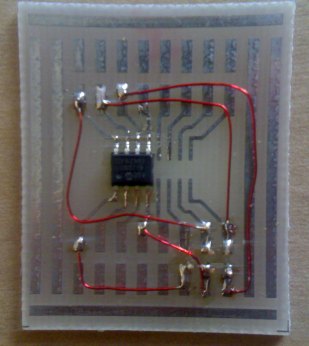
The photo shows the PIC chip soldered to
the board and 5 short tinned copper wires to create connectors for the
8-pin programming plug. The outline on the board shows where the female
socket aligns with the pins. The pins are made from 0.45mm tinned copper
wire, soldered to the board and cut to 5mm.
The photo below shows fine enamelled wire (0.2mm) connecting the programming pins to the chip.
The photo below shows the 5 pin socket mounted on the board and connected with very fine wire:
5 pin programming socket connected to the chip
Identifying the wiring to the 5 pin socket
The connector between the PICkit2 and prototyping board.
Use 6 pins from a 0.1inch header strip, bent to 90°
after soldering to the matrix board.
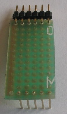
The top of the connector showing the 6 pins bent to 90°
The underside of the connector, showing the 5 fine wires:
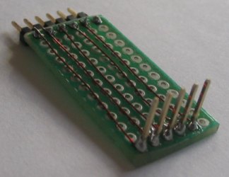
The underside of the connector
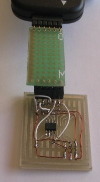
Photo of the connector joining the PICkit2 to the prototyping board:
If you want to program a through-hole 8-pin chip, here is the Programming Board:

8 pin programming board for
through hole chips
The photo below shows the LEDs and
resistors connected to the board and the supply leads for the chip, with
a 100n across the chip.
The chip is now ready to be programmed and tested.
THE NEXT STEP
Learn to program.
17/9/07