|
THE |
The H-Bridge is designed to drive a motor clockwise and anticlockwise.
To reverse a motor, the supply must be reversed and this is what the
H-Bridge does.
An H-Bridge can be made with SWITCHES, RELAYS, TRANSISTORS or MOSFETS.
Note: Some circuits are just demonstration circuits and need
"damper diodes" (protection diodes) to reduce spikes.
Do not make circuit "A." It can easily create a SHORT-CIRCUIT. It is
only a demonstration circuit.
Switch A and D will make the motor rotate clockwise.
Switch B and C will make the motor rotate anti-clockwise.
Switch A and B will create a BRAKE.
Do not close switch A and C at the same time.
Do not close switch B and D at the same time.
An improved design is shown in Circuit C. It does not create any
short-circuit:
H-Bridge with a relay:
The top diagram shows the underside
of a double-pole double-throw relay
The motor is active at all times. Push
the button to reverse the direction of rotation.
H-Bridge with 2 relays:
This circuit has an advantage. It
has FORWARD, OFF, REVERSE and BRAKE (off is BRAKE). The relays are single-pole change-over.
The first two circuits above are manual.
For a project such as a robot or car, we need an ELECTRONIC circuit -
one that is controlled by a "CONTROL CIRCUIT". The Control Circuit
outputs a signal (or a number of signals) to control an H-Bridge.
Here is a circuit of a Hex Bug. The Control Circuit consists of the
first 3 transistors. These amplify the signal from the electret
microphone and produce a signal that is able to charge a 47u
electrolytic. The next two transistors provide inverted signals to the
H-Bridge and are part of the Control Circuit. The H-Bridge consists of
the last 4 transistors.
THE MOTOR
The type of motor we will be powering is a 3-pole (or 5-pole) with
two brushes, similar to the following images:
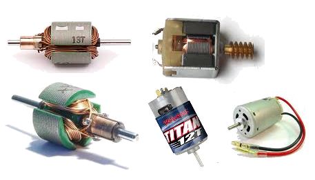
These motors come in
different shapes and sizes and have an output from 2,000RPM to
more than 16,000RPM.
They operate on less than 1v to more than 24v and the current they
require can be less than 100mA to more than 5 amps.
They all have some things in common:
1. They all have a permanent magnet called the FIELD MAGNET.
2. They all rotate in the opposite direction when the supply is
reversed.
3. They all take a high current when starting and a lower current when
rotating (spinning) at maximum RPM (Revolutions Per Second).
4. They all take a higher current when loaded - (the motor is
driving a load). A load may be placing your fingers on the output
shaft or driving through a gearbox and lifting a load or driving wheels
via a gearbox.
The torque (twisting ability of the output shaft) depends on the voltage
and current as well as the strength of the field magnet and the
quality of construction (the closeness of the field magnet to the
armature).
THREE THINGS
To drive a motor forward and reverse, the circuit must deliver a voltage in one direction, then in the
opposite direction.
It must also be able to deliver a "running current" (operating
current) (say up to 1 amp)
and a "starting current" (up to 5 amps), and a "loaded current"
(up to 5 amps). The transistors must be capable of passing a "stalled
current" without being destroyed.
The power supply must be capable of delivering a high current so the
motor will START-UP under load.
THE H-BRIDGE
The circuits we will discuss are called a transistor H-BRIDGE.
The active sections of the circuit create the letter "H" to
produce the
term "H-Bridge."
There are a number of different H-Bridge designs and the actual circuit
will depend on the number of transistors, the type of layout,
the number of control lines, the voltage of the bridge, and a number of
other factors.
That's why we have a number of different designs to cover these variations.
DESIGN 1
This design uses 4 transistors. Both inputs must NEVER be HIGH (this will
create a short-circuit and damage the transistors). However this circuit
is a good
design. The voltage on the H-Bridge can be any voltage and the control
voltage just needs to be higher than 1v. The circuit provides OFF
feature when both inputs are LOW but does not provide BRAKE feature.
DESIGN 2
This design uses 6 transistors to
do the same job as the circuit above. It does not have any advantages
over the circuit above
and simply uses extra components. The input voltage must be more than
1.5v for A and B must be higher than 4v to turn
off line B. When line B is less than 3.5v, it activates
the circuit. The timing of the inputs will prevent any "shoot through"
current.
DESIGN 3
This design requires the supply
voltage to the 74C14 to be the same as the voltage on the H-Bridge (5v
to 18v). The circuit provides BRAKE feature when the output of both
gates are the same (either HIGH or LOW). There is a "shoot
through" current during the time when the inverters change state
and this occurs as follows:
When the output of the gate is low, the bottom transistor is not turned
on but the top transistor is fully turned ON. When the output of the
inverter rises, the top transistor is ON and the lower transistor is
also turned on. When the inverter is HIGH, the top transistor is turned
OFF. During the time when the inverter is changing from LOW to HIGH,
both transistors are turned ON.
The HIGH on the motor will be
rail voltage minus the collector-emitter voltage (about 0.3v). The total
voltage-drop to the motor will be about 0.6v.
DESIGN 4
This circuit does not have the
"shoot through" current during the time when the inverters change state
but it does not have the same performance as the circuit above.
The voltage on the IC and H-Bridge must be the same. The transistors are
EMITTER FOLLOWERS and the voltage on the motor will be less than the
voltages on the circuit above because the HIGH on the motor will be
determined by the output voltage of the IC, minus the slight drop across
the 1k and the voltage drop across the base-emitter junction of the
transistor (a total of about 1v). The total voltage drop to the motor (due to both
sides of the bridge) will be about
2v.
The circuit is only suitable for a low-current motor as the 74C14 can
only supply 10mA and the 1k base resistors will limit the current
available through the transistors. The resistors can be reduced to 470R.
DESIGN 5
This circuit requires 4 inputs
and the HIGH inputs must be about 12v. The LOW inputs need to be as
close to 0v as possible. With correct timing of the
inputs, no "shoot-through" current will be produced.
DESIGN 6
This circuit uses a combination
of MOSFETs and transistors:
Input A HIGH, Input D HIGH - forward rotation
Input B HIGH, Input C HIGH - reverse rotation
Input A HIGH, Input B HIGH - not allowed
Input C HIGH, Input D HIGH - not allowed
DESIGN 7
This circuit controls the speed
of a 12v drill and drives a MOSFET. The H-Bridge is a reversing switch
(double-pole double-throw). The MOSFET will deliver up to 30Amps.
The frequency of the oscillator is in the range 550Hz to
about 6.5kHz, with an off period of about 2.6us.
PWM 12v CORDLESS DRILL MOTOR
CONTROLLER
DESIGN 8
This circuit uses 2 555 IC's to
provide forward and reverse motor-control. It does not have an "OFF"
position. When pins 2&6 are tied
together, the 555 becomes a Schmitt Trigger, detecting when the input is
above 2/3 of rail voltage and below 1/3 rail voltage.
The only problem with a 555 is the output voltage on pin 3. It does not
rise to rail voltage and does not fall to 0v. The HIGH can be about 1.5v
less than rail voltage and the LOW can be 0.7v above the 0v rail. The
actual HIGH and LOW from the chip will depend on the supply voltage and
the current taken by the load.
DESIGN 9
This circuit produces speed
control in forward and reverse direction. It does not have an "OFF"
position.
DESIGN 10
This circuit uses buffer
transistors on the output to deliver up to 4 amps to the motor. It does
not have an "OFF" position. As mentioned above, the output
from a 555 (pin 3) is less than rail voltage and since the BD679
transistors are "emitter followers" they will have at least 2v5 drop
across the collector-emitter terminals and thus need heatsinking. The
motor will not see more than 8v5. [This is not a very efficient
H-Bridge.] The most efficient H-Bridge use transistors in an arrangement
shown in Design 1-6 and 15. These arrangements have the lowest
voltage-drop across each of the transistors. This means the maximum
voltage will be delivered to the motor and thus the motor will produce
the maximum torque (power) and will take the maximum current when fully
loaded. Even a slight voltage drop to a motor will be noticeable when
the motor is under load, so it is important to have a power supply that
is capable of delivering a high current and a 'low-loss" H-Bridge.
DESIGN 11
This is a half-bridge circuit. It
is low-cost and effective. It requires a "split-supply." This is a 6v
battery tapped at 3v or two 3v batteries. The input voltage needs to be
about 1v. Both inputs must NOT be HIGH at the same time. The
circuit has: Forward, OFF, Reverse.
DESIGN 12
This circuit uses a half-bridge
to dive a motor in the forward/reverse direction. It does not have an
"OFF" position.
DESIGN 13
This circuit needs just one
input-line
from a microcontroller to produce forward/reverse. It does not
have "OFF" position. The input must be 0v for forward and 5v
for reverse.
When we say 0v on "A" we do not mean simply removing the 5v but taking
"A" directly to the 0v rail - in other words, "shorting A to 0v."
This is done via an output from a previous stage called a DIGITAL STAGE
that produces 5v when HIGH and 0v when LOW.
DESIGN 14
This circuit uses 4 x BD679
Darlington transistors to drive a motor: Forward - Off - Reverse. Two
inputs are needed and both must NOT be HIGH at the same time. It
does not have a BRAKE function.
![]()
DESIGN 15
This circuit is a SOLAR TRACKER.
It uses green LEDs to detect the sun and an H-Bridge to drive the motor.
A green LED produces nearly 1v but only a fraction of a milliamp when
sunlight is detected by the crystal inside the LED and this creates an
imbalance in the circuit to drive the motor either clockwise or
anticlockwise. The circuit will deliver about 300mA to the motor.
The circuit was designed by RedRok and kits for the Solar Tracker are available from:
http://www.redrok.com/electron.htm#tracker
This design is called:
LED5S5V Simplified LED low power
tracker.
![]()
To select the type of H-Bridge for your particular application, you need to match the H-Bridge inputs with the outputs from your circuit. Some H-Bridges need 1v to activate each leg of the bridge and others need slightly less than rail voltage to activate. In other words, they are active-LOW, but the voltage will need to rise to say 12v to turn the line off.
Some of these requirements are very difficult to achieve, so you should pick a simple design. Some H-Bridge circuits are over-designed - such as using an LM311 comparator to drive each side of the bridge. This can be replaced with a BC547 transistor on each side of the bridge.
In addition, some bridges drop (lose) 1v or more on each leg and this will reduce the power of the motor considerably. The answer is to supply the bridge with a higher voltage. You can supply a motor with a slightly higher voltage and get the maximum performance from the motor. The motor will run much faster on no-load, but you will get the power you need when it is loaded.
DESIGN 16
Bidirectional Analog Solar Tracker or Sensor
This circuit can be fund here: http://www.redrok.com/electron.htm#ledblue
The circuit uses N channel
IRF3708 MOSFETS in the low side and P channel
SPP18P06P in the high side.
The pair of BLUE
LEDs generate a differential voltage applied to the gates. The diodes
cause these voltages to always be above ground. If one side is higher
than the other, one
IRF3708 MOSFET turns on harder and and enables the
SPP18P06P MOSFET on the opposite corner to also turn on causing
the motor to turn. If the differential voltage is the other
way the motor reverses.
This circuit requires a small bias current be pulled out of the MOSFET gates to compensate for the leakage currents going into the gate from the positive supply which would could cause both MOSFETs to turn on; a bad thing. A pair of resistors could be connect from the gates to the emitters to absorb the approximately 20nA of leakage current. Or you can use diodes that have more leakage current than the MOSFET gates.
The 1N4148 universal high speed switching diode has about 20nA of leakage current; more as the temperature goes up. The reason normal 10MΩ resistors don't work is they consume more current than can be supplied by the BLUE LEDs. Low leakage diodes such as the BAS416 don't work in this circuit is because their leakage current is too low.
DESIGN 17
Change-over every 30 seconds
The following circuit pulses a latching relay every 30 seconds. The
circuit only consumes current during the 50mS latching period.
The values for the timing components have not been provided. These can
be worked out by experimentation.
DESIGN 18
High Current H-Bridge-1
This circuit will deliver 3 amps
to a 12v motor:
DESIGN 19
High Current H-Bridge-2
This circuit will deliver up to 3 amps
to a 6v motor. Use TIP100 (NPN) and TIP105 (PNP) for 8 amp
H-Bridge. Forward and reverse signals must not be applied at the same
time as this will create a SHORT-CIRCUIT. 1N4148 diodes will not
be suitable. Use 1N4004 diodes.
DESIGN 20
This circuit will operate from a
5v microcontroller and provide forward/reverse/brake. Use TIP31/32 and
BC547 transistors. The input transistors work in an unusual way. They
are emitter-followers but they have the load in both the collector and
emitter circuits.
DESIGN 21
DESIGN 22
This circuit does work however the
transistors in the bridge will not provide a high current.
The current-capability of the bridge comes from the ability of the
transistor to amplify the current entering their base. Let us
consider Q3.
The current entering the base of Q3 via the 1k resistor will only the
about 1mA and this means the collector-emitter current will be a maximum
of 300mA.
The current-capability of Q6 will be higher.
When Q2 is turned on via the 10k on the base, we will assume the control
voltage is 5v and 0.5mA will enter the base of Q2. This will allow 100mA
to flow through the collector-emitter terminals of Q2 and this will be
adequate to completely turn ON Q6.
The current capability of Q6 is 500mA.
You can see the limitation of the circuit is Q3 and a motor will draw
300mA or more when under load.
To make the circuit more reliable, POWER TRANSISTORS are needed in the
bridge.
DESIGN 24
This circuit looks very good until you realise the transistors are
DARLINGTON and they produce about 2v to 2.5v across the
collector-emitter terminals. This means you can lose up to 5v for a 12v
supply and the motor will have almost no strength.
In fact the supply can be 1v higher than the motor-voltage to allow for
the losses in the bridge and this will give the motor full strength. You
can even increase the supply by up to 3v to 5v to produce enormous
torque when needed and use PWM to control the speed of the motor (RPM -
and thus torque) for all other situations.
For this circuit you can increase the supply by 5v and then add another
3v to 5v to achieve the maximum from the motor.
The use of four opto-couplers allows a microcontroller to control the
bridge as all the control lines are completely isolated from the bridge.
http://www.mcmanis.com/chuck/robotics/tutorial/h-bridge/bjt-circuit.html
DESIGN 25
This circuit takes into account the maximum gate voltage of about 12v
for the MOSFETS used in this design. The two 4k7 are voltage dividers and the
resistors turn OFF the P-Channel
MOSFETs when the transistors are not activated. The input voltage can be as low as 2v but the circuit is
designed for 5v input from a PIC microcontroller. That's why
you need the transistors, because the 5v micro will not go high enough
to turn off the P-ch MOSFETs.
A03400 MOSFET - N-Channel SMD 5 cents on eBay
about 2-3amp about 100milliohms
A03401 MOSFET - P-Channel SMD 5 cents on eBay
about 2-3amp about 100milliohms
COMPARING TRANSISTORS WITH MOSFETS
The advantage of a MOSFET is obvious when you understand the voltage across the collector-emitter junction is about 0.5v to 0.7v and even 0.9v when the transistor is allowing a fairly high current to pass. This means you lose about 1.4v to 1.8v in a bridge-arrangement.
MOSFETS have a turn-on resistance between DRAIN and SOURCE (or SOURCE and DRAIN) of about 100 milliohms and this means a voltage drop of only 0.1v when 1 or 2 amp is flowing.
This produces a loss of only about 200millivolts but the important fact is the heat in each MOSFET will only be about 100milliwatts and the device can be quite small and not require a heatsink.
In many cases you will require and input voltage or more than 2v and maybe up to 5v to fully turn on the MOSFET and for this you will need a digital output from a microcontroller.
You must make sure the top and bottom FET in a totem-pole does not turn ON at the same time and this will create a short-circuit across the supply.
The program needs to have a long time-delay between the motor going clockwise and then going anticlockwise, because the motor will seem like an absolute SHORT-CIRCUIT when it changes direction.
DESIGNING AN
H-BRIDGE
To get a motor to start under load requires
at least three times the running current. In addition, a motor take 3
times the running current when it is loaded.
That's why an H-Bridge must be able to deliver a HIGH CURRENT.
To deliver a high current, the transistors must be fully SWITCHED ON. In
other words they must be fully SATURATED.
To fully saturate a transistor, the base current must be about 1/10 the
collector-emitter current.
Most transistors have a gain of about 100 but this only applies when the
transistor is passing about 10mA. To get a transistor to pass a high
current, the base current must be increased to about 10mA for every
100mA collector-emitter current.
Transistors are not linear devices and that's why this requirement is
rarely mentioned.
Most specification-sheets highlight the qualities of a transistor and
fail to mention the problems you will encounter.
That's why you have to drive the output transistors in an H-bridge via a
DRIVER TRANSISTOR.
The driver transistor will have a gain of about 50 so the input current
to the bridge will only be a few milliamps.
The other factor you have to take into consideration is the
VOLTAGE-DROPS across each leg of the bridge.
A saturated transistor will drop about 0.3v whereas a Darlington
transistor will drop about 1v and a MOSFET will drop only about 0.05v.
An emitter-follower will drop about 0.7v
You need to build a test-circuit and measure the voltage drops on each
leg before committing to a particular design. The performance of a motor
will fall considerably if it does not see full rated voltage.
You can increase the supply voltage to a bridge to account for the
voltage-drop across each leg. This will increase the no-load RPM but
allow the motor to produce maximum torque.
If you are using MOSFETs, the gate must be at least 0.6v higher than
the Source. This is the case with an IRF3708 as it has a very low
turn-on for the gate. However many MOSFETS need about 3v before they
will start to turn on.
Here is an example of what we mean. The maximum voltage seen by the
motor is 9v due to the fact that the top MOSFET needs 3v between the
gate and Source, for it to turn on. The Source will be 3v lower than the
gate:
CAUTION
There are many H-Bridge circuits on the web that do not work, so you
have to be careful.
See our
Spot The Mistake Page 11 for H-Bridge circuits that do not work.
Other circuits are over-designed, so compare your needs with the circuits
above.
2/1/2012