
|
|
TERMINOLOGY: A coil can be used as a "pick-up" to detect magnetic or metal objects. It can be called a TRANSDUCER, Inductive transducer, magnetic transducer, coil, pick-up, inductor, magnetic coil, pickup coil, inductive loop, inductive sensor, magnetic sensor, metal detector, comparator, gold detector, crack detector - to detect cracks in welds etc, head - as in a tape recorder. It can have a core made of iron or ferrite and be called an INDUCTOR. It can have a moving iron core and be called a SOLENOID. An inductor can be used to smooth the ripple in a supply, or it can be used to generate a voltage higher than the supply and it can be wound on "poles" to create a motor. It can have an adjacent winding and become a transformer, isolator or step-up device. It can be a current transformer, or even a linear motor. And there are possibly dozens more . . . |
THE INDUCTOR AS A "PICK-UP."
Now we come to an important feature of a coil when it is used as a SENSOR.
When a magnet passes a coil (this includes the action of moving towards or away from a coil), a voltage is generated in the turns in the form of a sinewave.
We use the term "sinewave" to indicate the approximate shape of the waveform to distinguish it from other shapes such as "square wave," "exponential" or "glitch." A sinewave is a continuing waveshape with a gradual rise and fall as shown in the following example:
The same type of waveform is produced if the magnet passes the end of the coil, into and
out of the end of the coil or if the magnet passes through the centre.
If the magnet is moved rapidly, the amplitude of the waveform INCREASES
(and there will be more "up's ad down's" in the same time-interval on
the diagram above).
The amplitude is also determined by the strength of the magnet.
There are three important points to note.
The first is the voltage produced by the coil as it
passes the end of the coil.
When the magnet is directly opposite the end of the coil, the change in
magnetic flux is zero and thus the voltage produced by the coil is zero.
The second point is the change in voltage produced by the coil.
The output voltage changes from positive to negative during the very
small portion of excursion when the magnet moves from a forward to
reverse direction as seen by the end of the coil.
The third point is the coil produces zero voltage when the
magnet is not moving.
If the magnet moves at a faster rate, the voltage produced by the coil
will be greater as shown by the animation below:
If two or more coils are placed in close proximity
with one or more coils providing a magnetic field, when a magnet or metal
object is passed through the field, the waveform produced by the
sensing coil is altered. The size and shape may be very small but amplifying stages
can produce amazing information.
This is the principle of a metal detector (gold detector) or a coin
detector in a vending machine.
The resulting waveform can discriminate between a coin and a "slug," an aluminium can, a
"pull ring" or a gold nugget.
This type of detector is beyond this discussion. We will only be
discussing how to detect the frequency of the pulses and the amplitude of
the voltage from a single coil.
For an inductive pick-up to be successful, the magnet passing the end of
the coil must be powerful and pass near to the end of the coil.
The output of a coil will generally be less than 700mV and must be AC
coupled to a transistor so that the voltage produced by coil will modify
the biasing of the transistor as shown in the diagram below:
In the diagram below, the magnet is passing the coil and when it is receding from the coil, the voltage produced by the coil turns the transistor OFF and the voltage on the collector rises.
![]()
The coil can be connected to a two-transistor arrangement to produce a square-wave output, suitable for circuits that require a noise-free signal:
A very simple circuit using a coil is shown in the diagram below. It is
our METAL DETECTOR -1.
It uses a 16 turn coil (approx 6" dia) to detect metal objects such as
coins etc. The circuit oscillates at approx 140kHz and the frequency
produced is picked up by an AM radio to produce a quiet spot on the dial.
When a piece of metal is placed near the coil, the frequency of the
circuit is altered and this is picked up by the radio as a low frequency
tone. The circuit is extremely sensitive and
a shift in frequency of as little as a few hertz will be clearly heard.
ROTATION
A motor is an example of a rotating inductor. Most small motors are 3-pole (the minimum number of poles for self-starting) and if a motor is used as a generator, the output will correspond to the speed of rotation.
For a 3-pole motor, three waveforms are produced for each revolution and the following diagram shows the type of waveform produced:
![]()
If the motor increases in RPM, the waveform changes:
![]()
A detecting circuit can be used to count the pulses and determine the
RPM.
By putting fan blades on the shaft of a motor, you can measure wind
velocity and the output of heating and cooling systems etc.
The output from the motor can be calibrated by placing the fan outside the window of
a car traveling at a known velocity.
THE INDUCTOR AS A FILTER - also known as a CHOKE
When an inductor is placed in a circuit and reduces the
ripple, as it does in the circuit below, it is also known as a CHOKE
- it "chokes off" the ripple. This is old terminology and is called
Jargon. (Jargon are words or sentences that are only understood by those
who work in the particular
field or "area" or job.)
We have already covered this feature at the beginning of this
article but since it is so important, we will go over it again.
This
time we will cover some of the features of a coil and
one of its hidden "magical properties." This magical property is
the ability of a coil (inductor) to produce a BACK VOLTAGE or REVERSE VOLTAGE that
opposes an increasing or decreasing voltage.
This is how the inductor smoothes (reduces) the ripple in the voltage
emerging from the rectifier.
It all starts when a voltage increases (or decreases) in amplitude.
Any increasing voltage allows an
increasing current to flow and this current increases the magnetic flux
produced by the coil and this flux cuts all the other turns of the coil
to produce a "back voltage."
This is the situation with the inductor "L" in the circuit below:
When current flows, the
voltage-waveform after the inductor, will be smaller than
the waveform entering the inductor. The size of the waveform from the
bridge
will depend on the ripple from the transformer. The diagram above shows
a waveform before and after the inductor but this is just a
representation. It is not a true indication of the size of the waveform.
A power supply contains electrolytic called filter electrolytics and the
diagram below shows one placed before the inductor and one after the
inductor.
This discussion is very
complex because we are constantly discussing voltage waveforms then
current waveforms. But this is the way it has to be.
The other thing that is hard to understand is the term "DC." When we say
"DC" we mean a steady or unchanging voltage or current. Even though the
real meaning of DC is "Direct Current" we still refer to an unchanging
voltage as "DC." Again this is jargon and that's why you need to
understand the meaning of the words.
The voltage waveform entering the inductor will actually be something like 10v DC with a ripple of say
300mV and 9.5v with a ripple of 50mV leaving the
inductor.
This is shown on the diagram below:
The size of the "output" waveform (from the inductor) will
depend on the inductance of L and the value of the load. If the load is
an amplifier, the current will be changing all the time according to the
level of music or speech. If the load is a globe, we call the load a
"steady load." By this we mean the current is steady.
Even if you are supplying a steady load such as a globe, the waveform
(ripple) entering the inductor will create a "back-voltage" in the
inductor that will reduce the peaks and prevent the lows getting any
lower.
This is due to the input waveform having a "ripple component." If the
input voltage was "pure DC," the inductor would not be needed. This is just an example of the operation of the inductor. There
will be a voltage drop across the indicator due to the resistance of the
winding. This can be proven by connecting the inductor to a battery
(such as a car battery) and measuring the voltage drop across it for any
given load.
Now we go back to our example: The output ripple is not constant.
As the current is increased, the output ripple will increase. This is
due to a number of factors.
The transformer will not be able to supply the higher current and its
output voltage will drop. The electrolytics will provide less filtering
at the higher current (see circuit below) and the inductor will become
"magnetically saturated" and not produce the same filtering.
All these characteristics will combine to produce a varying ripple
voltage on the output.
There is another factor to consider.
You simply cannot select an inductor by inductance alone. For instance,
you cannot simply say "use a 10,000uH choke." Not all 10,000uH chokes
are the same. Here is an example of 3 different 10,000uH chokes.
But before we do, remember this:
Ten thousand microhenries is the same as 10 millihenries.
1,000nH = 1µH
1,000µH
= 1mH
1,000mH = 1Henry
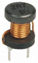
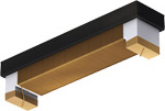
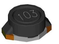
The following photos show different types of chokes. All have the same
inductance (10,000uH) but they will all produce a different output
because they have different coil-resistances. The second inductor seems
to be up-side-down, but the two ends are soldered to the PC board. It is
a surface-mount item.
 |
 |
 |
|
10milliHenry
2R7 Max current 3A |
10milliHenry
15R Max current 2mA |
10milliHenry 33R Max current 20mA |
The photos above do not show the real size of the components but you can see
each has a maximum current rating.
The current rating is the dominant factor.
That's why a 10mH choke can have so many different sizes.
THE INDUCTOR IN A POWER
SUPPLY
An inductor can be used in a power supply to reduce the ripple.
In most power supplies this is done with electrolytics, however we will
explain how the inductor operates.
The inductor only operates on the fluctuating part of the voltage.
If the voltage rises, it increases the magnetic flux and this is called
expanding flux. This flux cuts all the turns of the coil and produces a
voltage in the turns that is opposite to the incoming voltage.
Thus the increasing voltage does not enter the inductor.
This is how the inductor reduces the ripple on the output.
In the following circuit, the output has a reduced ripple due to the
inductor:
The following diagram shows an inductor with a closed magnetic circuit.
The "magnetic circuit" is shown via the arrows. And an
inductor with an AIR GAP.
An
"open" magnetic circuit is shown above via the colour-coded inductor.
The "magnetic circuit" is the core but the flux does not form a
continuous loop. This type of magnetic circuit is very inefficient and
has high losses. But it is quite acceptable if the magnetic flux is kept
to a low level where the core is not saturated.
DESIGNING AN INDUCTOR AS A FILTER (choke)
Designing an inductor for the above application is a very complex
mathematical problem. We do not know the ripple on the input to the
inductor or any of the voltage values as a small transformer as show in
the diagram has a very poor regulation factor and the output can be up
to 60% higher than the stated output so that the voltage drops to the
required level on full output current.
The best thing is to have a range of inductors and try them.
If you are winding your own inductor it is best to add too many turns to
a core and gradually remove them as needed.
Nothing beats "actual applications" as there are too many variables to be
able to design something from a chart.
If you don't know where to start, look at a power supply. Remember the
frequency of this power supply is either 50Hz or 60Hz. It is not a 40kHz
design. The inductance will be much higher than for a 40kHz circuit.
The same approach is recommended for any type of inductor.
An inductor is very difficult to design.
Projects do not always consume a constant current and the ripple present
on the unfiltered side of a power supply needs to be viewed on a CRO.
Rather than using complex mathematical formulae to work out the value of
an inductor, the easiest way is to try different values.
A choke in a DC circuit has to have an AIR GAP. That's why it is called
a CHOKE. This is to differentiate it from an INDUCTOR.
In a DC circuit (one that has ripple) voltage will be present all
the time and current will be flowing all the time. This means the choke
will be producing magnetic flux all the time and this flux will SATURATE
the magnetic core. This means an ordinary inductor will be worthless.
But if a sheet or cardboard is fitted between the top and bottom
sections of the magnetic core before it is dipped into a sealing
compound to prevent the wire and other parts vibrating when using the
component, the cardboard will produce an AIR GAP.
When you fit the component to a circuit it will produce magnetic flux
and all this flux will be lost in the air gap. The air gap actually has
to be the right width but 0.1mm will be a good start.
This means the current flowing through the device will produce magnetic
flux and it will all be lost in the air gap and when additional current
flows (due to the input voltage rising) the extra flux will be delivered
to the magnetic circuit.
When the input voltage reduces, the magnetic flux will collapse and pass
into all the turns of the winding and produce a voltage that will add to
the lower voltage and the output voltage will be slightly increased.
The choke prevents the voltage rising and prevents the voltage dropping.
There are limits to this and if you want something to reduce a 1v ripple
at 1 amp, the choke will weight say 100gm and be quite expensive.
This can be done with electrolytics that are much smaller and much
cheaper.
Chokes were originally used because they came as part of a speaker field
coil and size and weight did not matter.
But today's technology with switch-mode power supplies and
miniaturisation means high-frequency operation and size and weight and
cost all point towards using electrolytics.
THE WIRE
The size of the wire (the thickness) is an important factor when
designing an inductor.
It is always best to use the thickest wire for the application.
WHY?
The thickest wire produces the best result.
But finding the best thickness (gauge) is a complex problem.
Let's explain:
In some cases the wire-size is easy to work out. For a transformer, the
size of the former (the plastic bobbin on which the wire is wound) and
the area (space for the winding) is already known. You will also know
the number of turns required for each volt and thus the total number of
turns will be known. The size (gauge) of wire can be found from a table.
But an electromagnet (or solenoid) is different. This is basically a DC
component, although it will work on AC (say 50Hz or 60Hz).
These devices are designed to produce magnetic flux (to pull in an
armature or core or collect scrap metal - such as in a metal-yard) and
the flux is produced by multiplying the number of turns by the current
flowing though the coil. This is called AMP-TURNS.
Theoretically, the same flux can be produced by one turn and 100amps or
100 turns and one amp or 500 turns and 200mA.
But the current will depend on the gauge of the wire (as thin wire has a
higher resistance - and this will limit the amount of current that will
flow).
So, the maximum flux will depend on selecting a wire-size. Working out
how many turns can be fitted onto the former (wound on the bobbin) and
thus the total length of wire can be determined. This will give you the
resistance of the coil and thus the current (use a table to find the
resistance and Ohm's Law to find the current). Multiply the number
of turns by the current. Select another gauge of wire and eventually you
will get a table of values. From this table you will see a maximum
value.
If you are designing an inductor for an AC voltage or any fluctuating or
changing voltage, you will utilizing the coils: "magic property."
This is the fact that the expanding or collapsing flux from each turn
cuts all the other turns of the coil to produce a voltage in the
opposite direction. This is called the INDUCTANCE of the coil and it
means the coil does not only produce magnetic flux as described in the
electromagnet or solenoid above, but it also has an effect of limiting
or reducing the current you can deliver to the coil. This is because a
coil, solenoid or inductor always limits or reduces the current at the
instant you apply the voltage.
If you are constantly utilizing this feature by supplying a rising and
falling voltage, the coil will behave completely differently to a
solenoid (that has a DC supply connected to it for a long period of
time).
This means you must treat the coil completely differently to a solenoid.
It will produce completely different results, however it is best to use
the thickest gauge available.
WHY?
The thick wire allows more of the flux to pass through the adjacent
turns of the winding and thus
produce a higher reverse voltage.
In addition, the winding will have a lower resistance and this will allow a
higher current to flow and thus create more flux.
THE INDUCTOR IN "FLYBACK"
We mentioned above, one of the "magical properties" of an inductor is
its ability to produce a "back-voltage" or "reverse voltage."
There is an even-more-magical extension to this.
If a voltage is applied to an inductor and then removed, the
back-voltage will be VERY HIGH. It can be 100 times (or more)
higher than the applied voltage.
This is the principle of the ignition system in a car. The distributor
connects the ignition-coil to the battery of the car via the points and
then the points open.
The collapsing magnetic filed in the ignition-coil is passed from the
end of the coil to the distributor rotor-cap, and this is the rotating part of the
distributor. It sends the 20,000v to the appropriate spark-plug.
So, the collapsing property of an inductor has been known for a long
time and it has also been used in electronics for many applications.
Uses such as electric fences, high voltage generators, EHT circuits in
TV's, switch-mode power supplies.
This back-voltage is also produced by relays, motors, door-latches and
where-ever a coil is energised.
In most cases this voltage is higher than the operating voltage of the
components in the circuit and it must be prevented from damaging them.
In the case of relay, the back-emf, (this is what the back-voltage is
called) is snubbed (reduced) by the diode. The back-voltage has the
opposite polarity to the supply and this voltage is placed directly
across the diode and it forms a very low resistance path to absorb the
energy.
Another way to prevent the high voltage damaging the circuit is to
provide high-voltage insulation and shielding. Apart from
spike-suppression capacitors across the chips, there is no other way to
prevent high voltages damaging a circuit.
THE INDUCTOR and the word "IMPEDANCE"
When we talk about the
value of an INDUCTOR we say: What is the IMPEDANCE of the inductor?
In other words we are asking: What is the effect of the inductor having
on the circuit?
In other words, if we replace the inductor with a resistor, what is the
value of the resistor?
The answer is its INDUCTIVE REACTANCE and is symbolized by the letter
"X" and is measured in ohms, just like a resistance.
When an inductor is placed in a circuit that contains a waveform, the
inductor produces a back voltage and this voltage increases as the
frequency increases. This means the inductor presents a changing effect,
according to the frequency and its INDUCTIVE REACTANCE changes.
You cannot measure the value with a multimeter. You have to work
it out by taking other values, such as measuring the frequency and the
impedance of the coil.
Using the formula:
XL
= 2πfL
we can find the reactance at any particular frequency.
THE INDUCTOR in SWITCH-MODE POWER SUPPLIES
Switch-Mode power
supplies are everywhere in electronics.
Since the introduction of high-voltage transistors, these type of
supplies are now found in "plug-packs," (wall-worts) and all
types of phone chargers.
But the question is: How do you work out the value of the inductor.
Firstly you want the inductor to be as small as possible and as cheap as
possible.
Firstly you have to know the current that will be passing in the
circuit. This will give the gauge of the wire.
Next you have to know the pulses into the inductor will be 2 or more
times the average current that will be passing through the circuit.
This is because the inductor will be passing twice the current for half
the time as the remaining 50% of the time it will be delivering current
to the output part of the circuit.
Now, the next part is technical. It takes a very short period of time to
pulse the inductor and generate the maximum magnetic field. If you pulse
it for longer than this time, the energy is wasted in excess magnetic
flux that will not be converted to energy when you cease the pulse.
We have chosen an inductance with a very low inductance to keep the size
very small and it will only take a few microseconds to fully energise
it. This means the circuit must be operating at a very high frequency
to keep the "charge-time" below the time needed to fully energise the
inductor.
If you supply energy to an inductor during the time when it is producing
magnetic flux, it appears as a very high resistance - may be 10 or 20
times the actual resistance of the coil. The "winding" may have a
resistance as low as 0.1 ohms or maybe 1 ohm but it will appear as a
resistance of maybe 10 ohms. But when the inductor eventually produces
the maximum flux (this is when the magnetic circuit is saturated) the
circuit sees the inductor as 0.1 ohm and it can easily blow-up the
driving transistor. That's why you have to get the timing correct.
[When you are "charging" an inductor - in other words, when you
are supplying energy to an inductor and increasing the magnetic field,
the current through each turn is called EXPANDING FLUX and it is
cutting all the other turns and producing a microscopic voltage in each
turn that is opposite to the voltage you are supplying and this means
you maybe supplying 10v and the back voltage is 9v. This effectively
means you are supplying only 1v and thus only 1/10th the current will be
allowed to pass through the inductor. That's how the inductor
appears to have ten times the resistance.]
Now back to the topic:
That's how we get operating frequencies of 40kHz or 400kHz and even
3MHz. These are all of a duration that prevents saturation. The
"ON-TIME" is slightly less than the time required to saturate the
inductor.
The inductor is actually used in FLY-BACK mode in many circuits where the circuit is
turned off very quickly and the magnetic flux produced by the inductor
collapses very quickly and is passed to the receiving circuit.
The inductor actually produces a very very high voltage at a low current
but the magic of magnetism will convert this very very high voltage into
a voltage determined by the receiving circuit (the receiving circuit
limits the voltage to a pre-determined value) and the current will rise
to a value so that the input energy will be delivered to the output
(less a few percent losses). You simply multiply the volts and current
and time to get the input energy and this will be the output energy. It
is in the form of about 50% ON and 50% OFF.
This FLY-BACK phenomenon is only produced if the supply to the inductor
is turned off very quickly (instantaneously). If you turn off the supply
slowly,
the inductor will output a reverse voltage but its value will be
governed by the device that is lowering the voltage (such as the driver
transistor and the high-voltage phenomenon of flyback
will not be produced. The magnetic field will just "fall-back" into the
turns and be determined by the driver transistor as the transistor will
still have an effect on the current flowing in the circuit.
So, how do you select an inductor.
Look at other circuits and see what value they have used.
Alternatively buy a set of inductors and try each one. Use a weak
battery to drive the circuit and test the output. You will see a gradual
rise in performance and then a lowering in performance.
Choose the peak performance and drive the circuit with a better
power-supply.
You don't need any mathematics, calculations or skill. Just
experimentation. That's how these circuits were developed in the first
place. EXPERIMENTATION.
THE SECRET
The following circuit
uses an inductor to separate the 3.6v across a 1 watt LED from a 15v
power supply.
This circuit explains the secret: "HOW AN INDUCTOR WORKS."
The resistance of the inductor is less than one ohm and it sees about
14v on the left lead and 3.6v on the right lead.
So . . . how does it work?
How does it allow 14v to be present on one side and 3.6v on the other
side. The 1R resistor between the inductor and LED only has about 0.3v
across it.
Obviously the resistance of the inductor is not creating the 14 - 3.6 =
10.4volts across the leads.
It must be something to do with the turns of wire on the ferrite core.
On the right lead of the inductor is a 100u electrolytic. This capacitor
has the effect of preventing the voltage rising or falling. It keeps the
voltage fixed and stable.
When the BC327 transistor turns ON, it sends a pulse of current to the
left lead of the inductor. This current enters the inductor and produces
magnetic flux that cuts all the turns of wire and produces a voltage in
the opposite direction.
This voltage is nearly the same value as the voltage entering the coil
and the result is very little current will flow though the inductor.
This current is exactly the correct amount to fully illuminate the LED.
The inductor can only prevent too much current flowing FOR A VERY SHORT
PERIOD OF TIME.
That's why the oscillator is a very HIGH FREQUENCY.
That's the secret behind the operation of the inductor.
It creates a voltage across it that limits the current flowing through the
turns.
Of course the inductor must be selected to have the correct number of
turns and the correct wire-size and correct ferrite-size.
CONCLUSION
This discussion has covered only a fraction of the mysteries of the
inductor. There are special ways to wind an inductor for high voltage
circuits. There are special ways to reduce the inductance and there are
special cores to increase the inductance.
There are ways to tap an inductor to get all sorts of results such as
high current, high impedance, low impedance and impedance-matching. You
can add a second, third and fourth winding to get isolation,
impedance-matching, high voltage or high current. Inductors can be made
long, short, fat or any shape to fit onto a circuit.
That's why there are so many shapes, sizes and pin-outs.
To understand "the Inductor" you need to make a simple circuit that you
can adjust and change the physical properties of the inductor.
The following circuit is a perfect example for experimenting. It uses a
single 1.5v cell to illuminate a white LED. We know a white LED requires
at least 3.2v for it to illuminate, so the circuit is "magically"
increasing the 1.5v to a higher voltage.
The coil (the two coils) is actually a transformer and it is acting in
FLYBACK MODE.
It has no core (just air) and you can separate the turns and see what
effect it has on the operation.
This bike flasher uses a single transistor
to flash two white LEDs from a single cell. And it has no
core for the transformer
- just AIR!
All Joule Thief circuits
you have seen, use a ferrite rod or toroid (doughnut) core and the turns
are wound on the ferrite material. But this circuit proves the
collapsing magnetic flux produces an increased voltage, even when the
core is AIR. The fact is this: When a magnetic filed collapses quickly,
it produces a higher voltage in the opposite direction and in this case
the magnetic field surrounding the coil is sufficient to produce the
energy we need.
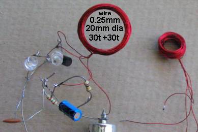
Wind 30 turns on 10mm (1/2" dia) pen or screwdriver and then another 30
turns on top. Build the first circuit and connect the wires. You can use
1 or two LEDs. If the circuit does not work, swap the wires going to the
base.
Now add the 10u electrolytic and 100k resistor (remove the 1k5). The
circuit will now flash. You must use 2 LEDs for the flashing circuit.
THE IMPROVED BIKE FLASHER CIRCUIT
The secret to getting the maximum energy from the coil (to flash the LEDs) is the maximum amount of air in the centre of the coil. Air cannot transfer a high magnetic flux so we provide a large area (volume) of low flux to provide the energy. The larger (20mm) coil reduced the current from 20mA to 11mA for the same brightness. This could be improved further but the coil gets too big. The two 30-turn windings must be kept together because the flux from the main winding must cut the feedback winding to turn ON the transistor HARD.
When the transistor starts to turn on via the 100k, it creates magnetic flux in the main winding that cuts the feedback winding and a positive voltage comes out the end connected to the base and a negative voltage comes out the end connected to the 100k and 10u. This turns the transistor ON more and it continues to turn ON until fully turned ON. At this point the magnetic flux is not expanding and the voltage does not appear in the feedback winding.
During this time the 10u has charged and the voltage on the negative lead has dropped to a lower voltage than before. This effectively turns off the transistor and the current in the main winding ceases abruptly. The magnetic flux collapses and produces a voltage in the opposite direction that is higher than the supply and this is why the two LEDs illuminate. This also puts a voltage through the feedback winding that keeps the transistor OFF. When the magnetic flux has collapsed, the voltage on the negative lead of the 10u is so low that the transistor does not turn on. The 100k discharges the 10u and the voltage on the base rises to start the next cycle.
You can see the 100k and 1k5 resistors and all the other parts in a "birds nest" to allow easy experimenting.
Note: Changing the turns to 40t for the main winding and 30t for the feedback (keeping the turns tightly wound together by winding wire around them) reduced the current to 8-9mA.
Go to:
P4
2/07/22