|
The |
This is an amazing project . . .
us$65.00 plus $7.50 post
Order kit
Fully assembled version $199
Order Infinity Bug
Download Infinity Bug as .pdf (420k)
(not all links work in .pdf)
|
The INFINITY BUG is connected
across the phone-line of a distant phone (in parallel mode). |
This project requires a high degree of soldering. It uses surface-mount
resistors, capacitors transistors and diodes.
It can only be assembled on the PC board supplied in the kit as the
Latching Circuit is already soldered to the board and the project will not work
with substitute components.
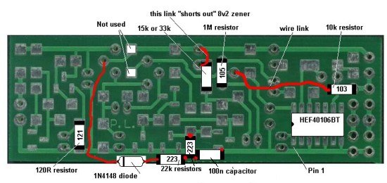
The underside of the complete Infinity Bug
The topside of the Infinity Bug
 Infinity Bug Schematic
Click schematic above for larger version.
(move your mouse off the screen and back again to get the enlargement arrows for large schematic)
or click HERE to download schematic as .pdf
HOW THE CIRCUIT WORKS
The Infinity Bug consists of a number of blocks, plus components that
perform very important tasks.
The following diagram shows the function of each of the components:
The Infinity Bug connects
across the phone line and takes very little current as most of the circuit
is not active when in the "waiting" state.
This is called "leeching" and the Infinity Bug is a leech device as it gets
its operating current from the phone line.
Some phone systems detect as little as 0.5mA and if more than 1mA is drawn
from the line, it remains engaged.
The voltage of a phone line varies from 42v to 55v, depending on the
service-provider and the Infinity Bug will
operate on this voltage range.
When the Infinity Bug is connected to the line, the "line voltage" will drop
to about 36v, due to the current drawn by the bug. This will not upset the
operation of the phone system.
The bridge on the front-end allows the project to be connected either way
around and allows for the annoying feature of some phone lines. They create
a voltage reversal as soon as the phone is picked up and this would defeat a
Bug that requires a polarized voltage.
The only two sections drawing current during quiescent conditions is
the whistle-detecting circuit made up of the BC 547 and its surrounding
components. This section draws less than 0.25mA. It is frequency sensitive and will not detect the
33Hz ring frequency. The other section is the "timing section," made up of
the 40106 IC. This is a hex Schmitt trigger (the same as 74C14).
Another feature of feature of the circuit is the 8v2 zener.
When a phone (that is connected to the same line as the Infinity bug) is
picked up, the line voltage drops to about 12v and the whistle-detecting
circuit does not see any voltage, as the 8v2 zener drops nearly all the available
voltage.
Thus the circuit has a self-cancelling feature.
The principle of operation of the bug has been described above and when the
handset is put back on the phone, the line voltage rises.
This allows the person at the other end of the line to whistle.
The tone produced by the whistle is passed through the 47n and 4k7 to the base of the BC 547
transistor.
The transistor amplifies the signal to produce a 2v p-p signal that is
turned into a DC voltage by the 10u. This turns on the latch circuit
and the base of the BC 639 is raised to produce a voltage on the emitter of
about 4.5v
The actual voltage on the emitter of the BC 639 is determined by the 120R in
the emitter leg of a BC 547. The BC 547 is almost fully turned on by the 10k
resistor between the collector and base.
The 47u on the base of the BC 639 holds the base rigid to any AC signals so that the
transistor operates as an emitter follower.
The transistor acts as an impedance-matching stage as the phone-line has a
relatively low impedance while the pre-amplifier section has a quite-high
impedance.
Finally, the microphone is connected to microphone pre-amplifier stage
consisting of a BC 547 transistor, 1M bias resistor, 4k7 load and 22n input
capacitor.
Thus the audio section consists of 3 stages in a very unusual arrangement.
This is necessary as the signal has to be delivered to the same line as
supply voltage.
The Infinity Bug turns off after about 3 minutes due to a timing circuit
connected to one gate of a hex Schmitt trigger IC.
The voltage across the IC is set to 6v2 via a zener so the timing can be
controlled as the lower threshold at which the chip will change state is
determined by the supply voltage.
When the line voltage rises to 50v, the 47u in the timing circuit is rapidly
charged via a 47k resistor that is connected to the rail via an 18v zener.
This put a maximum of 6v2 on the 47u as the input of the chip cannot rise
above the supply on the chip due to diodes on the input of the gate.
When the Infinity Bug is turned ON via a whistle, the line voltage falls to
about 12v and the 47u in the timing circuit does not see any charging
voltage as the 18v zener removes this voltage.
The 47u is now slowly discharged via a 2M2 and when the voltage falls to
below 2v, the output of the gate goes HIGH. This HIGH is passed to the base
of a BC 639 via a 22k and 1u electrolytic.
The transistor removes voltage from the latching circuit and the Bug drops off
the line. The 1u allows a pulse to activate the "turn-off" transistor.
The 1M on the base discharges the 1u so that it is uncharged
in readiness for the circuit timing out.
The 1N4148 signal diode connected to the rail of the project is connected to
a 22k and 100n. This arrangement detects the "ring voltage" (approx 150v)
and the zener of the signal diode allows the 100n to charge via the 22k. All
diodes have a maximum reverse voltage and the diode we have chosen has a
voltage of about 110v. This voltage can be called it "zener voltage." Any
voltage above this "zener voltage" will pass through the diode. We have
used this feature to keep the whistle-detect transistor turned on during the
time when the phone is "ringing."
There are a number of other features of the circuit contained within the
Latching Circuit that allows the project to operate successfully, but these
have been kept secret and are mounted on the PC board when a kit is
purchased.
CONSTRUCTION
Before any construction is undertaken, you must be
familiar with surface-mount technology.
We have a number of simple projects to allow you to get practical experience
with these devices. See our
Phone Ring project, for example.
Once you have soldered these components you will understand the difficulty
in handling and soldering them to the board.
The surface-mount components are generally the first to be soldered to the board.
But in this project, there are through-hole components and surface-mount
components. If you add the surface-mount components first, make sure you do
not "fill-in" any of the holes for the through-hole components. One
component, a 1M (105) is mounted on the same lands as the base-emitter leads
of a BC639 transistor.
The printing on the surface-mount chip indicates pin 1 at the bottom-left as
shown in the diagram. This is one of the few times when the printing on a
device indicates pin 1.
The case of the electret microphone goes to the "-" on the board. This is
the negative rail and runs along the bottom of the board.
Click
HERE for full size
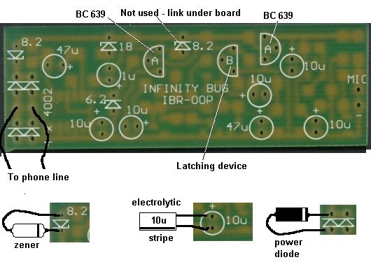
Topside of Infinity Bug
The diagram below shows the modifications to the underside of the board as
well as some of the surface-mount components in their correct positions as
per the circuit diagram.
Refer to the placement diagram for the position of each component.
The resistors are identified by either 3 digits or 4 digits.
Click for the complete range
of SM resistor markings for 3-digit code:
Click for the complete range of SM resistor markings for 4-digit code:
Solder one end by firstly adding a little solder to one land and placing the
resistor in place.
Hold the resistor in place with fine tweezers or an opened-out paper clip
and bring the iron to the end of the resistor to re-melt the solder. The
resistor will sit down onto the board. You can now solder the other end.
The surface-mount capacitors are not identified and
are contained in a strip for this project in the following order:
Do not remove any of the capacitors until they are required.
Only remove one at a time and solder it to the board. The size of a
capacitor is not an indication of its values as some are
multi-layer.
The transistors and diodes are contained in the same package.
The transistors are marked "1K" or "1G" and the diodes are marked "A6."
They are temperature sensitive and are more difficult to solder than the
resistors as they are smaller and must be soldered quickly.
Once all the surface-mount components are fitted, the through-hole
components are added.
All the through-hole components are polarity sensitive and must be fitted
around the correct way.
The final things to add are the electret microphone and the two leads with
alligator clips.
TESTING THE INFINITY BUG
To fully test the Infinity Bug
you will need two phone lines. This is not often available and the next best
solution is to build a "Test Rig."
The 470R resistors are current-limit resistors and the LEDs indicate when the
phone and Infinity Bug are on the line.
The Infinity Bug can be tested with the following Test Circuit:
Connect the Bug to the test circuit shown above and pick up the left-hand
phone.
Whistle into the mouthpiece and the Bug will pick up the line and you will
be able to hear the ticking of a clock in the room.
Pick up the second phone and the Bug will drop off the line.
Replace the second phone and whistle.
The Bug will pick up the line again.
Keep listening to the Bug and it will drop off after about 2-3 minutes.
Whistle again and the Bug will pick up the line.
Repeat this again and if everything woks perfectly, the Bug is fully tested.
IF IT DOESN'T WORK
The first thing to do is
measure the current taken by the Bug when it is connected to the line.
It should be less than 0.5mA and only the whistle-detecting stage should be
active.
You will need a CRO to measure the amplitude of the signal produced by the
whistle-detecting stage at the collector of the transistor. It should be
about 2.5v p-p.
The DC voltage across the 10u electrolytic that provides a turn-on voltage
for the latching circuit will rise to 0.6v and the bug will turn on.
When the bug is turned on, the emitter voltage on the BC 639 will be about
4.5v. This voltage is created by the value of the 120R resistor as it is the
load resistor for the project.
The 4.5v becomes the rail voltage for the audio stages and the only way to
test the audio stages is with a CRO.
Since the Bug is connected to a current-limited power supply (the 470R in
the test power supply provides current limiting) you can use a jumper on the
project with fear of damaging anything.
To test the audio stages, connect a jumper between point "A" on the board
and the base of the BC 639 amplifier transistor. You will be able to hear
the faintest sounds in a room.
If audio is not detected, measure the voltage on the collector of the first
audio transistor. It should be about 2v.
The second transistor should have about 4.5v on the collector and 4v on the
emitter.
The most common fault will be a faulty connection to one of the
surface-mount components or a damaged transistor.
You will need a CRO to detect the passage of audio through each of the
stages.
There are a number of critical components in the circuit and the audio
section is very important.
The current taken by the audio section causes the rail voltage to drop to
about 4v2 when the bug is active. This voltage is determined, mainly by the
120R resistor in the emitter of the second stage. The transistor is turned
on by the 10k resistor between the base and collector and the transistor is
actually a common-emitter device, although it appears to be an emitter-
follower.
If the 120R is increased, the voltage on the section rises and creates a
feedback squeal.
If the 22k load for the microphone is decreased, a squeal is also created.
If the microphone is removed, a squeal is also created.
Everything is complex as we are creating an audio signal on the same lines
that are supplying the voltage to the circuit.
A fault-finding service available from Colin Mitchell by clicking
HERE.
| |
|