|
Joule Thief |
|
|
|
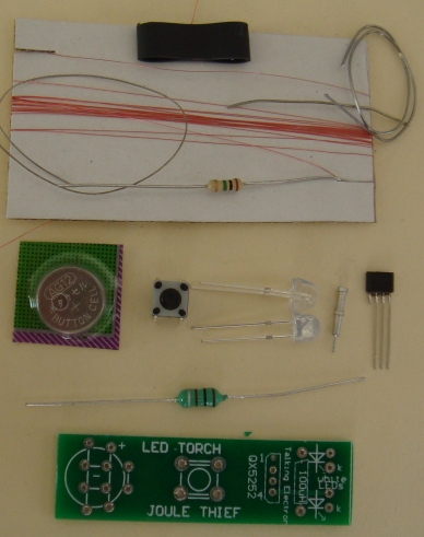
INSTRUCTIONS This kit shows how a single 1.5v cell can drive an oscillator containing an inductor to produce a high output voltage. This voltage is delivered to two LEDs to provide amazing illumination. The kit also contains very fine wire and a former on which to wind 200 turns to create an inductor of about 80 microHenry. This is an exercise in winding very fine wire and soldering the ends of the wire to the leads of the resistor. This is a 1M resistor and its high resistance does not affect the inductance of the coil. Two machine pins on the board allow the 100uH inductor to be fitted and then replaced by the hand-made inductor to see if it produces the same brightness. You can then experiment with other home-made coils to see the brightness they produce. You can measure the current taken by the circuit across the switch and decide which inductor is the most efficient. You can also test other LEDs by placing them across the leads of one of the white LEDs. |
The CIRCUIT
The circuit is very simple. All
the work is done by the 5252F chip.
It contains an oscillator, a high speed diode and a power transistor.
All these components inside the "IC" that looks like a 4-leaded
transistor!
This IC is smaller and cheaper than all the parts individually and is
less expensive than the competition (that costs 70 cents).
We can produce a complete project for a few dollars and it has two "test
features."
You can place a LED across one of the LEDs on the board and find out the
colour as many LEDs come in a "clear-as-glass" package and you cannot
tell the colour until they are illuminated.
The other feature is INDUCTOR TESTING.
The current taken by the circuit changes according to the value of the
inductor.
You just need a few reference values and you can work out the value of
an inductor within the range of the inductors you have used as samples,
or slightly higher or lower values.
The layout using
component pictures.
Using a 220uH, the circuit takes 13mA and illuminates
2 white LEDs very brightly.
Using 100uH the circuit takes 30mA and the LEDs are really the same
brightness.
Using 33uH the circuit takes 80mA and the LEDs are just about the same
brightness.
Obviously the 220uH creates the most efficient circuit.
The QX5252F is capable of delivering more than 100mA to the LEDs but we
only need 30mA.
Don't forget, we are measuring the current from the battery. When the
voltage is increased to 3.6v and the current is delivered to two LEDs,
30mA from the battery represents less than 12mA per LED.
The waveform produced by the inductor is very "peaky" or "spiky."
It consists of a spike that would normally be very high -something like
15v. But as soon as the voltage reaches 3.6v, the LED "turns ON" and
starts to produce light. A LED turns ON very very quickly and all
the energy in the spike that would normally be in the range of 3.6v to
15v, is passed to the LED to get it to illuminate. This voltage
activates the LED very brightly and it illuminates a dark room. After a
short time, the voltage of the spike falls to less than 3v and the LED
turns OFF.
The circuit now passes current through the inductor to produce magnetic
flux for the next cycle. The frequency of operation can be between 40kHz
and 160kHz.
During each cycle, the LED is turned on for less than 25% of the cycle,
but it is turned ON very brightly and our eyes see this brightness and
maintain the brightness for quite a few milliseconds after the event.
Look at the sun and then look away. Your eyes are washed out for a few
seconds. Or look at the flash of a camera. You cannot see for the next
few seconds.
This is called PERSISTENCE OF VISION and the pulsing of the LED becomes
a constant illumination.
The circuit takes pulses of current from the cell and delivers these
pulses to the LED.
This makes the LED very efficient and that's why the circuit can take as
little as 20mA to produce very good illumination.
Some of the flashing LEDs will not flash because the waveform is not
liked by the microcontroller inside the LED.
The 10u
does not make any difference with some flashing LEDs.
MAKING THE INDUCTOR
Two more of the same circuit but
drawn in a different way
to help you understand the layout of the components.
By simply adding a 1N4148 diode, the flashing LED works perfectly. You
don't need a Schottky diode as you have plenty of voltage "up your
sleeve."
Here is the modified circuit:
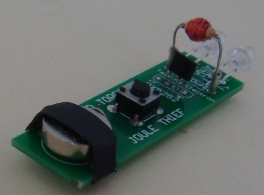
The 100uH inductor fitted
to the Machine pins
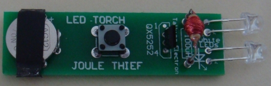
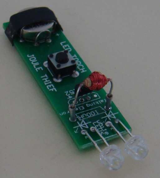
The hand-wound inductor fitted to the Machine pins
Wind 200 turns on top of the 1M resistor.
As the number of turns increases, you will find they may fall off the
resistor. To prevent this from happening, you wind the turns in a way
called BASKET WOUND or JUMBLE WOUND. Instead of winding the turns
side-by-side, they are wound by quickly taking the turn from one side of
the coil to the other and then back again. In this way the turns are
prevented from falling off the resistor.
If you make a good job of the winding you will be able to get 200 or
even 250 turns on the resistor.
If you connect the 100uH inductor provided in the kit IN SERIES with the
hand-wound inductor, you will get a value of about 180uH and you can
measure the current and look at the brightness to see if the brightness
has improved.
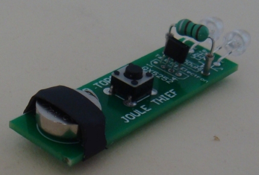
CONSTRUCTION
The cell fits on the end of the board and you need to solder fine tinned
copper wires to the board to make the contacts for the cell.
Start by fitting the fine tinned copper ire through the 4 holes in the
centre of the holder and solder them from underneath after you have
pressed the wire against the board.
Now make a loop of the thicker tined copper wire and solder it to the
two holes This loop should be just as high as the cell.
Now hold the cell in place while you fit fine tinned copper wire over
the top of the cell and pull the wire with pliers before making the
final soldering. The cell will now stay in position.
Pull the two wires together and solder them quickly at the top of the
cell.
A piece of heatshrink is provided in the kit.
Slip it over the cell and use the barrel of the soldering iron to shrink
the plastic on the underside of the board.
The tactile switch is easy to fit. Just solder the 4 pins.
Solder the two machine pins.
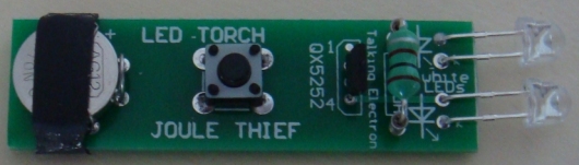
Solder the two white LEDs so they extend out the front of the board. The
short lead is marked with a "k" on the board.
Fit the 100uH inductor to the machine pins and the project is complete.
Press the tactile switch and the LEDs will illuminate.
You now have a handy TORCH.
| |
|
MORE
Talking Electronics.com
has described, written and designed lots more
circuits that come under the heading of JOULE THIEF.
They are actually INVERTER circuits or
more-accurately FLYBACK CIRCUITS.
A Flyback Circuit uses an amazing feature of an inductor
to produce a high voltage. When the supply is removed
from an inductor, the magnetic field it produces, will
collapses and produce a very high voltage. It can be 2
to 10 to 100 times higher. It depends on the design of
the inductor.
Rather than trying to explain all the physics of how
this occurs, it is easier to get an inductor and connect
it to a battery. Hold the wires and remove the battery.
You will get the biggest shock of your life. That's what
got me interested.
This is an enormously-complex field and to get you
interested, we have another article with circuits and
discussions on this link:
LED
Torch Circuits
7/12/2017