KITT
SCANNER
A REALISTIC SCANNER FOR KNIGHT RIDER MODELS
Page 2
to Page 1
![]()

|
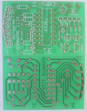
Kitt Scanner Circuit |
HOW THE CIRCUIT WORKS
The circuit consists of two building blocks. The first is a square wave oscillator made up of two transistors in a multivibrator arrangement and the second is a CD 4017 decade counter IC.
The multivibrator contains two extra components to speed up the waveform and make it acceptable for all brands of 4017's. Unless the output has a very fast rise and fall characteristic, some 4017's fail to operate properly. They either do not work at all or jump two or three outputs, losing the scanning effect.
The two speed-up components are the signal diode and 39k resistor and are essential for reliable operation.
The output of the multivibrator feeds into the CLOCK INPUT of the chip. From there is goes to a complex counting circuit inside the 4017. The circuit counts to 10 and only one output is active (HIGH) during each of the 10 steps.
Initially output pin 3 is HIGH while all others are LOW. After one clock cycle the second output (pin 2) goes HIGH while all others are LOW. After the next clock cycle pin 4 goes HIGH etc through to the 10th output which is pin 11. We could see the effect of these outputs going HIGH by placing 10 light emitting diodes on the lines. They would give a 'running light effect'. Remember this.
We have placed 10 signal diodes on the output of the chip so that we can illuminate a set of Light Emitting Diodes from one of two different lines.
Eight of these diodes form four OR gates to direct the appropriate outputs of the 4017 to the corresponding LEDs. The remaining two diodes equalise the brightness of the two un-gated LEDs.
The first 6 outputs operate the diodes in a normal running light sequence. The clever part comes with output Q6. It is taken to the 5th LED and this creates the effect of reversing the sequence. Q7 drives the 4th LED and this continues the reverse effect until the second LED. The chip has now completed one cycle and the first output is now turned ON. This illuminates the first LED to complete the full back-and-forth scan.
Each time the 4017 goes through its run of 10 outputs, the scanner completes one forward and reverse scan.
This is how the effect is generated. It is the first time anyone has used the chip in this way and it shows you don't have to stick to convention.
|
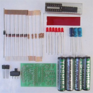
Complete set of components for the Kitt Scanner |
|
PARTS LIST |
|
1 - 330R 1/4 watt 2 - 22k 1 - 39k 2 - 47k 1 - 2.2u electrolytic PC mount 1 - 10u PC mount 1 - 22u PC mount 11 - 1N4148 diodes 1 - 1N 4002 diode 2 - BC 547 transistors 1 - CD4017 IC 1 - 16 pin IC socket 4 - 'AAA' cells 6 - 3mm red LEDs 1 - miniature SPDT slide switch 1 - piece of red plastic 1 - SCANNER PC BOARD |
CONSTRUCTION
The SCANNER is constructed on a PC board which has one end specially shaped to fit into a plastic model and give the LEDs the radius they need for alignment against a piece of red diffusing screen.
This end is shaped before any of the parts are fitted, by cutting the excess from the board with a pair of side-cutters. After this, the board is finished off with a file.
Refer to the photo before mounting the parts to see how and where they are placed. Some fit against the board and others are mounted upright to take up the least amount of space.
Start by inserting the 11 signal diodes. Some of these lay flat against the board while others are almost upright. The way they stand (or lay), depends on the distance between the holes and you will have to fit them as neatly as possible.
The 10 diodes (in a row) face the same way and the single diode in the oscillator faces downwards.
Next mount the row of 5 resistors and the single resistor which lays flat against the board. The resistors in the row stand on END and it is important to get the values correct. They are clearly marked on the overlay and you can also refer to the layout diagram in the article.
Next solder the input protection diode to the PC board. This diode stands on END.
Next fit the IC socket so that pin 1 identification (either a cut-out or corner missing from the socket) aligns with the dot on the PC board. This will make it easier to fit the IC correctly.
The two transistors are fitted so that they nearly touch the PC board and only a gap equal to the height of a resistor separates them from the board.
The three electrolytics are mounted so that the positive lead goes down the identified hole on the PC board. You will notice the negative lead is identified on the component while the positive lead is identified on the board. Do not get confused!
The last components to be mounted are the LEDs. Once you fit them, they cannot be refitted as the leads will be too short. So get it right.
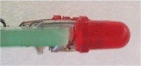
The cathode lead is the shortest and this goes directly to the track-work on the front of the board. It does not pass through a hole. The anode lead passes over the board and down a hole where it is soldered in place.
Cut the anode lead as shown in the diagram below and bend it to 90°. Cut the cathode lead very short and the LED is ready for mounting. Fit it onto the board and solder each lead very quickly to prevent damage to the crystal inside the LED.
This is an unusual way of mounting LEDs but suits our project perfectly.
There is one thing you must never do. Never spread the leads of a LED as this will crack the plastic encapsulation and it will be damaged. There will, however be some slight spreading of the leads as they are inserted and this is the maximum allowable.
|
Mounting the LEDs |
Fit only one LED and check to see if it has been fitted correctly. Fit the IC and connect the board to a 6v supply. The LED should blink on/off.
If it doesn't, check the orientation by looking into the body and noting a large 'cup'. This is the cathode and goes directly to the underside of the board. Place a multimeter across the LED, with the project working. The needle should swing up to 1.5v for a brief period of time.
If it does, but the LED doesn't light, you have possibly damaged it, either by separating the leads too far or overheating it when soldering.
If the LED does illuminate, continue fitting the rest until all are placed neatly in a row.
Make sure they continue the radius of the board so they fit behind the screen in the car.
Two power leads are soldered to the board and these must be long enough to reach the rear of the model.
The 4 AAA cells are mounted in the boot and soldered together to form a 6v battery pack. A small slide switch is placed under the car to turn the scanner ON.
Now is the time to test the project and watch the effect. You will find it quite hypnotic. If everything works well, mount the board up-side-down in the bonnet compartment so that it is parallel to the ground. Make up a couple of struts to support the board to keep it in position.
Everything is now ready for the final touches of presentation. Complete the assembly of the model and make sure all traces of wiring, batteries and PC board are removed from view.
I know you will be pleased with the effect, but break the news slowly to your friends. Say "Wouldn't it be nice if we had the real effect of the Knight Rider scanner!"
Then flick the switch!
IF IT DOESN'T WORK
There are two sections to this project. If the LEDs do not scan, the fault will lie in either section. You have to isolate which section is at fault.
Firstly test the multivibrator. Place a multimeter, set to VOLTAGE, between pins 14 and earth. The needle on the meter should oscillate, indicating the transistor section is producing a waveform. If this wave-form is present, the 4017 could be at fault. Check the voltage on pin 16. It should be rail voltage. Check the voltage on pins 13 and 15. It must be LOW for the chip to count. If the first LED remains ON, the 4017 could be damaged or the input waveform too low to clock the chip. Try a new chip.
The next stage is to isolate the chip from the multivibrator. This is done by isolating pin 14 from the circuit and connecting a jumper lead to it.
Take this jumper to rail and then to earth. This will produce a full transition on the clock line and hopefully cause the chip to count. If this is successful, the incoming clock pulses are TOO SMALL or of poor quality.
A CR0 would be handy to check the wave-shape but if this is not available, you can manually clock the chip via the transistor circuit. Firstly take one base lead to ground and then the other base lead to ground. While doing this you can measure the voltage on the collector of the output transistor and note that it changes from LOW to HIGH.
If the chip does not clock, the fault will lie in the output transistor. It may not be connected to earth. the diode may be around the wrong way, or creating a leakage which will inhibit the amplitude of the output pulse, or the resistor may be the wrong value. The only other possibility is the transistor. It may be damaged and thus will not amplify sufficiently.
If the chip jumps LEDs when scanning, the pulse shaper circuit maybe at fault or the amplitude of the signal is too low for the chip. It could also be the 4017. Some 4017's have Schmitt trigger circuits in the input line to reduce the effects of noise. Others do not have in-built Schmitt triggers. Try a different brand of chip.
If one or more of the LEDs fail to come on, place the multimeter on the relevant output and watch the needle. If it pulses HIGH/LOW, the signal is emerging from the chip and the LED will be at fault. (or the soldering). Try the signal on the other end of the diode. If it is not present, the diode is at fault or has been inserted around the wrong way.
If the scanner is running too fast, the electrolytics will be the wrong value or 'dry'. It could also be due to the wrong value of resistance in the base lines.
The 330R resistor in the cathode line of the LEDs is a current limiting resistor to prevent the LEDs taking too much current. Make sure it is connected to the circuit or the LEDs will not come on.
If you follow these suggestions your scanner should be working perfectly.
I hope you find it to be a captivating addition to your Knight kit.