|
THE
MICRO BUG |
$14.50 incl all parts and PCB
plus $3.50 postage to anywhere in the world
P1 to: P2
![]()
![]()
|
|
|
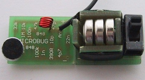
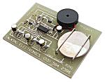
Micro Bug and Battery Box |
The main difficulty is the surface-mount transistors. All the rest of the components are easy to fit, once you get over the shock of their size, but the transistors are not only microscopic, they are temperature sensitive. They must be soldered quickly with a DELICATE IRON at the RIGHT TEMPERATURE.
We will discuss this more in a moment. I want to get in first so that anyone who has not built at least four of our previous projects, including at least one of our surface-mount kits, do not get the idea that this bug is going to be easy to put together.
| See Phone Ring. It is a surface-mount project to test your skills as soldering SM components. |
 |
Something we have been asked on a number of occasions is: “Why do we keep
producing so many FM transmitters projects?
Apart from the fact that they are always extremely popular, each of the designs
either incorporates an improvement over a previous design or a new feature.
A reader wrote to us suggesting we design one enormous project incorporating the
features of our VOX bugs, our Wall Bug and our long range bugs, with a switch
to select a particular feature.
This would be wonderful idea if it were practical, but it would defeat the
purpose of the designs as each demonstrates a different feature.
There is no circuit simpler than an FM transmitter. Nothing produces crystal
clear audio from two or three stages and transmits to a tuner to give the
equivalent of a high wattage amplifier. To make the circuit more complex by
adding extra features would defeat the purpose of starting with something
simple.
Each of the transmitter circuits we have designed incorporates a number of
BUILDING BLOCKS and studying these will help you; not only to understand how
the circuit works, but also with designing your own circuits.
Building FM transmitters is definitely a great place to start, as the cost is
low and the experience you get is invaluable.
DESIGN IMPROVEMENTS
Many of the designs in our transmitter series are on their second or third
improvement.
It would be wonderful to design a project that is perfect from the start, but
unfortunately this is not reality. There are always improvements and additions that
come along after we produce a project. Sometimes the improvements
are only small and sometimes they are considerable.
No-one is perfect and we would be the last to admit we are perfect.
However we can state our designs are by far the best we have seen, simply
due to the fact that we update and improve them to get them to the stage of
near perfection.
It's the “I help you, you help me” principle. I sell you something cheap and
you buy it in enormous quantity. That's how we work. Everyone can afford our
low-cost kits and that's how we stay in business. We help you with designs and
you give us feedback and improvements.
This has been the case with all of our projects. When they go into the field we
get feedback from constructors. We also have the advantage over other designers
in that we sell made-up devices as well as kits and we get first-hand ideas on
improvements. That's how we have got to the stage we are at.
And now for a
really challenging project.
SMALLER AND SMALLER DEVICES
We are constantly asked for smaller and smaller bugs. Some constructors think
it is easier to hide a smaller device.
But the problem with size is the antenna and the batteries.
It's no good having a micro-miniature bug if the antenna has to be 50-100cm
long!
The other problem is the size of the battery. As the battery gets smaller and
smaller, not only does the life of the bug reduce but the earth plane produced
by the mass of the battery is also reduced and the output of the transmitter is
reduced.
That's why really small bugs are placed in a metal case. It acts as a
ground-plane.
It all boils down to the optimum size for a transmitter and this seems to be
about the size of a matchbox.
This size gives us adequate room to fit two AAA cells, a switch and electret
microphone as well as a board containing conventional components. But sometimes
we have to pander to demand.
At the present, the demand is for a miniature bug.
That's why we have designed the MICROBUG. It is the smallest we can go using
readily available surface-mount componentry - even then the components are not
readily available, although some suppliers are listing packs of 10 of each
component. We had to import the very tiny slide switch
and microphone.
The circuit is our tried and proven two transistor design and has already been
presented as the Earwig project.
Even though the circuit is very simple, no-one has been able to improve its
performance and all we have done is use surface-mount components to reduce the
size.
I am going over the operation of the circuit once again because every
time I describe it, I include a few more details of how each component
works.
HOW THE CIRCUIT WORKS
The circuit consists of three stages, an electret microphone, an audio
amplifier and an RF oscillator.
The electret microphone consists of only two parts - a FET transistor and a plastic
diaphragm. There is nothing else inside the case. The 3-leaded FET has an
input, output and earth lead. The mylar diaphragm has been permanently charged with
a static charge and this is one of the secrets of the operation of the
microphone.
|
|
The FET transistor has a very high input impedance and because it is an active device, we call it a stage.
The gain of this device is extremely high because it is able to amplify the charges from a charged surface to produce an output in the millivolt range. When voice (or any sounds) are delivered to the microphone, the air vibrations are passed to the microphone through a tiny hole in the front of the case.
This causes the plastic diaphragm to move back and forth. It is situated very close to an earthed plate and if you have studied static electricity, you will know that charges on a charged surface redistribute when part of the surface is moved towards or away from an earthed surface.
This re-distribution causes charges to move in and out of a lead touching the centre of the diaphragm.
There are two factors that govern the sensitivity of the microphone. One is the manufacturing process and the quality of the charged mylar diaphragm. The other is the current flowing into the microphone via the load resistor. We cannot alter the charge on the diaphragm but the gain of the microphone can be increased or decreased by adjusting the current through the load resistor.
Further qualities such as the clarity of the pick-up is determined by the thickness (thinness) of the diaphragm and the electrostatic charge placed on it during manufacture. These factors cannot be changed by the user.
Creating a plastic that permanently holds an electrostatic charge has been a very difficult thing to do and that's why electret microphones are only a recent invention. Because we are down at the level of detecting individual charges, enormous amplification factors are required and unfortunately there is a wide variation in quality from one unit to another. For this reason they need to be tested and grouped according to sensitivity and for our project, we need the most sensitive type.
Poor quality units cannot be increased in sensitivity by reducing the load resistor as this will produce a lot of back-ground noise like bacon and eggs frying. One you have a good quality microphone, the output is passed to the first audio amplifier via a 22n capacitor.
This value can vary from 10n to 100n without any appreciable change in quality however it is always advisable to use the highest value capacitor to allow the low frequencies to pass through.
The audio amplifier has a gain of about 50 to 70 and passes the signal to the base of the RF oscillator stage.
The RF oscillator is designed to operate at about 88MHz and the frequency is set by the inductance of the 5 turn coil together with the 47p capacitor. These two components make up a circuit called a parallel resonant circuit (tank circuit).
The frequency is also determined by the transistor, the 10p feedback capacitor and also to a lesser extent by the biasing components (47k, 100k and 390R resistors).
When power is applied, the 1n base capacitor will gradually charge via the 47k resistor and turn the transistor on.
The base voltage will continue to rise and the 10p will have the effect of trying to prevent the emitter from moving. A point in time is reached when the energy from the capacitor is exhausted and it can no longer resist the movement of the emitter. The base-emitter voltage decreases and turns the transistor off. The current flow in the coil then ceases and the magnetic flux collapses.
This collapsing magnetic field produces a voltage in the opposite direction and whereas the collector voltage may have been 2.9v, it will now rise to over 3v and charge the 47p in the opposite direction. This voltage will have the effect of charging the 10p and the voltage drop across the 390R emitter resistor will be such that the transistor will be turned more firmly OFF.
As the 10p charges, the emitter voltage will drop to a point where the transistor will begin to turn ON and the current flow through the coil will oppose the collapsing magnetic field.
The voltage across the coil will reverse and the collector voltage will drop. This change will be passed to the emitter via the 10p and the result will be that the transistor will turn ON very hard and short out the 10p. After this the cycle begins again.
What we have is an oscillator that produces AC energy at 88MHz with the amplified audio signal fed into this stage via the 100n, varying the frequency of oscillation to produce the FM signals.
|
PARTS LIST |
| 1 - 390R (marked 392 ) 1 - 10k (marked 103 ) 1 - 33k (marked 333 ) 1 - 47k (marked 473 ) 1 - 100k (marked 104 ) 1 - 1M (marked 105 ) 1 - 4p7 surface mount 1 - 10p surface mount 1 - 47p surface mount 1 - 1n surface mount 2 - 22n surface mount 1 - 100n surface mount 2 - BC 848 transistors marked ‘1k’ 1 - 5 turn 3mm dia enamelled coil 1 - mini electret microphone 3 - 1.5v button cells 60cm very fine solder 1 - 80cm hook-up wire for antenna 1 - MICRO BUG PC board |
| See Battery Box $2.00 extra |
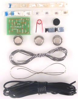
Micro Bug components
Before starting, place a tiny piece of blu-tack on the top-side of the
Micro-Bug PC board and push it onto your work-bench so it does not move - all
the components are mounted on the "underside" of the board.
Blue/Black line The colors and size will change
from one batch to another and from one manufacturer to another.
The Micro Bug from the
bottom. Notice how neatly the parts are positioned and soldered An
enlarged view of the underside of the Micro
CONSTRUCTION
All the components for this project are surface-mount.
This includes the two transistors,
Let me warn you once again, the components are very tiny.
Before opening the kit of parts you must prepare a clean space on your
workbench so the components can be taken out of the holding cells without being
lost.
You will also need a soldering iron with a fine tip.
We use a soldering iron that is commonly called a SOLDERING PENCIL. It is a
very small iron with a tip that is sharp enough to prick you!
If you do not have this type of soldering equipment, assembly will be much more
difficult and the neatness will not be as good as our photos.
You will be amazed at the improvement you get by simply using the correct
equipment and FINE SOLDER.
To get more information, go to our
soldering article.
Also,
see the range of soldering irons from a large supplier -
Howard Electronic Instruments Inc.
Ask Howard Electronic Instruments to quote on a very small iron and a roll of 0.7mm solder.
See hundreds of
articles
and pictures on soldering on Howard Electronic Instruments website.
Also see this
ARTICLE on soldering by WELLER.
Now we can get down to assembly:
Lay out a clean sheet of paper and place the strip of components so the
black band is to the left.
The first components to fit onto the board are the resistors and these are in
the strip in ascending order. This
means the values are: 390R, 10k, 33k, 47k, 100k and 1M.
The next components to fit to the board are the capacitors. Unfortunately they are not
marked and so you will have to be very careful when removing them so that they
are not mixed up.
The size of a capacitor chip is no indication of its value and so you have to
take our word that we have placed them in ascending order.
Even the colour of the substrate is no indication of a value so please don't
ring us up and say “I have a tiny pink capacitor and a tiny mauve capacitor and
a tiny purple capacitor, which is the 10p!”
The surface-mount capacitors are housed in a carrier strip, with a black
line at one end. The black line corresponds to the lowest value of
capacitance.
I know some people are going to plough into construction and lose a component
or two so the replacement strips will be available for $8.00 for the set of
capacitors $6.00 for the resistors and $4.00 for the transistors plus $2.00 for postage.
This is the best we can do so don't ask for individual components - you're
lucky we have a service for replacement parts.
When fitting the components to the board, open up the strip from the black-band
end and allow one chip at a time to fall out of its cell to a clean sheet of
paper on the bench.
If the component is a resistor, it will have markings on it. Turn it over to
reveal the numbers.
This is a three number code to indicate the value in ohms. Make sure it is
turned around so the numbers make sense. Sometimes you can hold a resistor
around the wrong way and it will appear to be a different value!
The markings for each resistor have been supplied in the parts list so
double-check the value before fitting it.
Pick up the resistor with a pair of tweezers or a paper clip that has a tiny
piece of Blu-Tack placed on the end and carry the chip to the board.
Hold the chip in place with the paper clip but take the Blu-tack away so that it
does not melt and contaminate the joint.
Bring up the soldering iron to one end of the chip and with your third hand,
add a small amount of fine solder and make a connection.
The art of soldering surface-mount components will take a little time to
master, but you
will find they are easier and quicker to fit than conventional
components.
We build hundreds of items for customers and the assembly workers have said
surface-mount devices are easier and quicker to fit.
Everything takes time to get perfect and since electronics is going in the direction
of surface-mount, now is a good time to get your hand in.
Every year, more and more of our consumer electronics are being converted to
surface-mount technology.
Already more than 40% mount is surface-mount and the percentage is increasing all the
time. The driving force is economics.
Even though surface mount components are slightly more expensive, the cost of
insertion is much lower as they are placed on the board with a
pick-and-place machine. These can fit components five-times faster than
conventional components.
But the real saving is in the size of the board. This can be reduced by as much
as 50% with components on one side or as much as 70% with components on both
sides.
The board can be made of much thinner material or even flexible, so the scope
for new produces is enormous.
Board for cameras, for instance, are made of paper-thin flexible material so
it can fit around the body of the camera with
flexible wiring to connect to the button, motor, battery and flash.
But the greatest advantage of surface-mount is the aesthetics. Surface-mount
looks professional and makes your product stand out from the rest.
Now back to the topic.
When you get to the capacitors, you must look into the
cell before letting it fall out so you can recognise it once it hits the
paper.
Refer to the diagram of the strip for the value and then the enlarged diagram
of the board for the position of the component.
It doesn't matter which way around the resistors or capacitors are placed and
they can even be turned over but there is one thing you must not do.
When you have soldered one end of a component you must not try to straighten it
up. This also applies to a component that is standing up slightly.
Any amount of force will fracture the substrate. Even slight pressure can
separate
the metallised end caps from their substrate and cause the component to go open
circuit.
That's why it is important to hold the component in place with the tip of a
paper clip while soldering the first end.
If the component shifts, you are in big trouble.
This is because YOU are going to take much longer to re-heat the end and
realign it.
If this happens with a transistor, forget it. The transistor will be damaged.
It a component moves, leave it misaligned and try to solder the other end as
best as possible. The damage you will cause in trying to straighten it will be
a nightmare to fault-find.
Another problem you will find is some soldering irons are magnetic and the
resistor will stick to the tip of the iron if you don't hold them down with
something such as a pair of tweezers or paper clip.
Just before we go to the transistors, let me give one final hint.
To reduce the heat build-up in a component, it is best to solder one end then
wait a few seconds for the component to cool down before soldering the other
end.
This is very important when soldering the transistors.
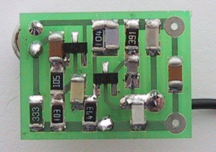
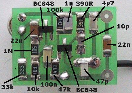
bug PCB. It shows the
placement of the
surface-mount components.
to:
P2
![]()