PIC LICK-1
Go to P1
P2

THE OSCILLATOR
The onboard 4MHz RC oscillator makes the instructions execute at one
million per second.
This is helpful when producing delay values. When using the PIC16F628,
the 4MHz RC oscillator inside the chip, is used.
INPUTS
When an input is not connected, it is called "left open" or
"floating." To make sure the
micro detects a LOW, an input must be taken to the 0v rail (commonly
called "ground").
To make sure the micro detects a HIGH the input must be taken to the +5v
rail. (It can be taken to a voltage higher than 5v, providing a
current-limiting resistor with a resistance of at least 1k for every volt on
the supply rail.) A floating input may detect a HIGH or LOW.
Any voltage above 2.4v will be detected as a HIGH and any voltage below 0v8
will be detected as a LOW. This means you should deliver a voltage as
close to 5v as possible to produce a HIGH and as close to 0v as possible to
produce a LOW.
Unused inputs do not have to be connected to any
level. If they are not connected, do not expect to get a known reading.
To make RA0 LOW, connect it to 0v via a jumper or switch. To make RA0
HIGH, connect it to +5v
as shown in the diagram above.
A LOW can be created by placing a transistor on any of the input lines
as shown in the diagram below.
When the transistor is "turned-on," (commonly called "bottoming" or
"saturation") the voltage between the collector and emitter is approx 0.35v to
0.5v and this is seen by the micro as a LOW. The buffer resistor on the
base of the transistor allows any voltage to be applied to the transistor
without damaging it. When the transistor is not turned on (called "cut-off")
the input of the microcontroller sees a HIGH via the 10k "pull-up" resistor.
The transistor-stage is an inverter. A HIGH on the input (via the 22k
resistor) is seen by the micro as a LOW.
 RESET
Reset is available as a
pin on the edge of the board. Normally you would not need this pin but when
developing a program, it is handy to reset the chip. This pin is taken to 0v
via a switch to reset the chip. It is only a momentary action.
Remove the link to start the program at address location 000.
OUTPUTS
The 8 output buffer transistors are "switches to ground." This is
called "SINKING." (When a transistor supplies a current it is called
SOURCING.)
The transistors in our project do not "supply" current to the output device but connect the
device to the 0v rail. The supply rail delivers the current and voltage.
To understand how this works, refer to the diagram below: 
Two of the transistors are fed via 220R base resistors, and six have 470R
base resistors.
If the gain of the transistor is 100, all transistors will deliver one amp
to the load. But if the gain is about 50, the six transistors with 470R base
resistors will deliver 10 x 50 = 500mA, while the two with 220R will deliver
the full 1-amp. Another module in the series is PIC Robot-1. It
has two "H-bridges" to drive two motors in either forward or reverse
direction. The transistors in the bridge are rated at 2 amp to allow for the
heavy starting current of a motor.
5v REGULATOR
The module has an on-board regulator. This is a 78L05 - a
positive 5v regulator
capable of delivering 100mA. This allows the module to be supplied from 8v to 12v.
The regulator ONLY supplies the chip. All the
current for the output devices is obtained from the main supply rail. This
supply can be any voltage from 3v to 12v (or more).
The regulator requires a minimum of 8v so that it will produce a 5v output.
If you want to supply the module from a 6v battery, the regulator can be
removed and a jumper placed between the in and out terminals. The power diode
must be included to drop the 6v to 5v5.
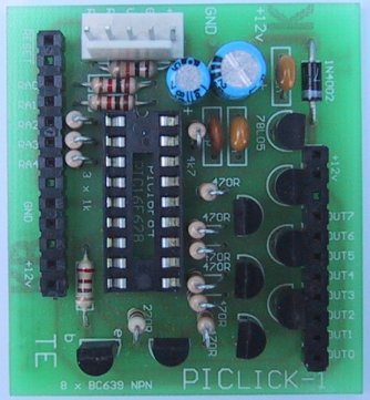
TOP VIEW OF PIC LICK-1USING AN
INPUT LINE AS AN OUTPUT
The input lines can be used as outputs. There is no problem with this. Just
make sure no switches are connected to the line if you are going to remove
the 1k buffer resistors.
The only feature you have to remember is RA4. It can only output a LOW. It
cannot output a HIGH. The
following circuit shows how it works.
RA0, RA1, RA2, and RA3 can be converted to outputs and the load current can
be up to 250mA.
RA4 requires a pull-up resistor and in our case the lowest value is about
22k. Any value lower than this will create a voltage divider on the base to keep the
transistor ON when the output of the micro is low. The base resistors can be
reduced to 220R, if needed, for all outputs. A 220R on RA4 will allow the
base-bias resistor to be 4k7 and the load current can be 100mA.
USING AN
OUTPUT LINE AS AN INPUT
Generally, very few input lines are needed in a project and PortA has 5
inputs. This should be enough to cover all requirements. It is not
convenient to convert one of the output lines on PortB to an input.
USES
The uses for PIC LICK-1
are up to you.
It has driving capabilities up to 1 amp per output and all outputs can be
activated at the same time, providing the power supply will deliver the
current.
The supply voltage to the load is totally independent of the PIC LICK-1
module. The module actually operates from
an on-board 5v regulator. If you supply the module from a 12v source,
this 12v will be available for each of the outputs.
This module is actually an extension of PIC LAB-1. The experiments on
PIC LAB-1 will show you the type of projects that can be created and if PIC
LAB-1 is not expansive enough for an idea, now is the time to implement
it on PIC LICK-1
PROJECT IDEAS
Ideal projects for this module include a set of
high-bright
running LEDs, as stop-lights for a car.
Many projects presented on the web and in magazines, covering projects such
as this, drive the LEDs from the outputs of the chip. This is quite
unsatisfactory if you want to produce a really good effect.
The answer is to drive them from a buffer transistor and deliver the maximum
current.
This can be 25-40mA for a normal LED and up to 100-250mA for special
high-bright LEDs.
Currents up to 4 times these values can be delivered for very short periods
of time and this is why you need high-current drivers.
TWO WAYS
There is actually two ways to illuminate a LED.
The simplest is to deliver a constant current of approx 25mA and the other
is to deliver 40mA for a duty cycle of 25%.
Both methods will produce the same output brightness.
This is one of the amazing features of a LED. It can be pulsed with a very
high current for a short period of time and the output brightness will be
the same as a lower constant current. But when you work out the difference
in consumption, the pulsed-mode consumes less energy.
In the case above it is 25:10.
The outputs of a PIC chip are limited to 25mA and this prevents the
pulsed-mode being employed.
However, with the
PIC LICK-1
you can deliver a higher current and new capabilities open up.
Apart from delivering a higher current, the two ports can be combined to produce
a run of 12.
This allows one input line for the start/stop button or an input from a sensor in
the car.
If you want a longer "run," you can multiplex two runs to get 20
outputs.
DESPERATE!
"I have a problem. I desperately need a relay or circuit that will take a set voltage & send
it to one device and send an ever-escalating variable to another device."
This is a request from Jeremy
A. from the Resource
section of Poptronics.
This is just an example of the type of request that comes to a design
engineer.
In this case, no further information was provided and the requirement is too
vague to start designing a prototype.
But when you get this type of requirement from the "factory floor"
you have to think very carefully before starting a design.
Most of the time the initial outline includes only part of the request.
After a few discussions the requirements include delays, signals, counting
and lots more.
Quite often it is best to design around a microcontroller. It allows easy
additions and modifications, especially when the requirements are not fully
known or understood.
CREATING A PROGRAM
Consider this project as a high-drive-current PIC16F84A or PIC16F628. You can now design
projects that require up to 1amp per output.
This is especially suited for model train projects; to drive relays,
motors, actuators or sequencers. It can also be used in automobile
applications and displays.
A request from a model train shop came in last week. They wanted a sensor on
the window to detect when a person was viewing the display. This consisted
of a photo darling photo-transistor and amplifier that detected a rapid
change in the level of illumination. The track was activated and a train was
required to travel down the track and reverse. The activation was required
for 3 minutes.
Photo transistors on each end of the track detected the loco and activated a
reversing relay.
Everything was done in the PIC LICK-1 module and it only required three
photo darlington transistors and two relays to produce the effect. Variety
was added by allowing the loco to travel partially down the track before
reversing. The photo detectors at each end prevented to train hitting the
buffers.
There are two ways to start writing a program. One is to start from scratch
and the other is to pull-apart a working program.
The easiest way is to use a previous program as a template. It will save a
lot of thinking a provide all the set-up instructions. Strip it down to the
minimum number of instructions and make sure you don't have any duplicate
labels.
To work out how to create a set of instructions to get the micro to carry
out a particular operation, refer to our
Library of Routines
and "Copy and Paste"
file. You can also get many ideas from the projects we have developed.
PROGRAMMING
To program a chip, the simplest way is to remove it from the board while
it is fitted to an extra socket. This makes removal very
easy. All you do is push the chip sideways and it will lift off the board.
Take it to the Multi Chip Programmer and use
IC-Prog
v5 to program the chip. Make sure the processor is PIC16F628 and the
oscillator is IntRC I/O. The fuse settings are discussed below.
All the instructions for the routines in a program, (approx 33) for the
PIC16F628 are exactly the same as the PIC16F84A.
TEMPLATE
When using a PIC16F628, it is important to set up the chip
so that the internal oscillator is activated (default oscillator is 4MHz),
and the comparators are disabled. This is done via the instructions in SetUp.
The configuration settings are shown in theTextPad file below.
Configuration settings are also on IC-Prog programming screen when
programming a PIC chip.
Load IC-Prog and bring up the programming screen:
Select PIC16F628 as the processor and IntRC I/O as the oscillator.
Code Protect: CP OFF
Fuses:
Untick WDT
Tick PWRT - a short internal delay in the chip will be activated
so that the power rails have time to settle down before the program is
started.
Untick MCLW
Tick BODEN - the chip will reset if the rail voltage goes below 2.5v and
returns to 5v.
Untick LVP - this is for low-voltage in-circuit programming, but you lose
in/out pin RB4!
Untick CPD - You don't need to code protect any program until you sell it
and don't want anyone to
copy the instructions. You can still "burn" the chip 1,000 times with Code
Protect activated as the chip will be erased when Code Protect is
active. When a chip is "burnt," the all the cells (memory locations) are
firstly erased, then re-programmed.
;Expt1.asm
;Project: New Idea
; use internal 4MHz oscillator
LIST P=16F628 ;f=inhx8m
#include "P16F628.inc"
__CONFIG _CP_OFF &_BODEN_ON &_PWRTE_ON &_WDT_OFF
&_LVP_OFF &_MCLRE_OFF &_INTRC_OSC_NOCLKOUT |
SetUp
Table1
Delay1
Count
Main |
ORG 0
MOVLW 07
MOVWF 1Fh
BSF 03,5
CLRF 06
MOVLW 01Fh
MOVWF 05
BCF 03,5
CLRF 2F
CLRF 06
GOTO Main
END |
;This is the start of memory for the
program.
;Disable the comparators
;File 1F is the CMCON file
;Go to Bank 1
;Make all port B output
;Load W with 0001 1111
;Make RA0,1,2,3,4 input
;Go to Bank 0 - the program memory area.
;Clear the flag file
;Clear the output port
;Tells assembler end of program |
|
When using a PIC16F628, the files for your program start at 20h and end at 70h. This
provides 96 files and any of them can be used as temporary storage and in
your routines. There is a further 128 files if you need them.
There is also a 128 byte EEPROM where you can store information that will
not be lost when power is removed from the chip. The EEPROM is not generally
used for short-term storage during the running of a program as it takes a
long time (in computer terms) to store a value in the EEPROM. The EEPROM can
only be written about 1,000,000 time and this can easily be exceeded when a
program is constantly executing.
MIGRATING A PROGRAM
Moving a program from a PIC16F84 to a PIC16F628 or vice versa is very
simple.
The files in a PIC16C84 are 00 to 2F
The files in a PIC16F84A are 00 to 4F
The files in a PIC16F628 are 00 to 7f
In a PIC16C84 and PIC16F84, files 00 to 0D are used by the micro, so that
the programmer can use files 0C to 2F or 4F for a PIC16F84A.
In a PIC16F628, files 00 to 1F are used by the micro, so that the
programmer can use files 20h to 7F.
To move a program from a PIC16C84 or PIC16F84A to a PIC16F628, simply add
20h to each file.
In other words, file 0C becomes 2C and file 1A becomes 3A, file 28h becomes
48h etc. You MUST increment ALL files so that you don't get two files such
as 2C.
All the instructions and routines in a program for a PIC508A, PIC16C84 and
PIC16F84 can be burnt into a PIC16F628, providing the file numbers are
increased as described above and providing you use instructions in a '508A
that are also suitable for the other processors.
It is very rare that a program is migrated from a PIC16F628 to a PIC16F84A.
If the files are located between 20h and 4F, no changes are needed. The
instructions in SetUp, to disable the comparators, are not needed for a
PIC16F84A.
TEST PROGRAM
We will now cover a simple program to test the
PIC LICK-1 module. The diagram below shows how to wire a switch and
two LEDs to the PIC LICK-1 to test the input and output ports. The program
outputs to all the 8 lines of Port B as a "LED Chaser." Up to 8 LEDs can be
placed on this port to see the complete effect.
A switch is placed on RA0.
When it is pressed, the LEDs "Freeze."
The supply voltage can be 8v to 24v. The voltage to the microprocessor is
fixed at 5v by the 78L05 voltage regulator. This is 100mA device. When an
output is active, the chip takes an extra 10mA. When all outputs are
active, the current taken by the micro is 100mA. The voltage regulator will
dissipate 500mW. This means the voltage across it can be 5v, when maximum
current is flowing. When the
supply voltage is above 12v, the voltage regulator will need to be
heat-finned or only some of the outputs can be active.
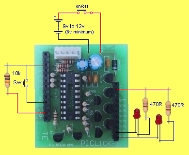
WIRING THE
PIC LICK-1
for the TEST PROGRAM
THE
PIC LICK-1
ARTWORK
;TestPgm.asm
;Project: Test PIC LICK-1
; use internal 4MHz oscillator
LIST P=16F628 ;f=inhx8m
#include "P16F628.inc"
__CONFIG _CP_OFF &_BODEN_ON &_PWRTE_ON &_WDT_OFF
&_LVP_OFF &_MCLRE_OFF &_INTRC_OSC_NOCLKOUT |
SetUp
Delay1
Main
Main1 |
ORG 0
MOVLW 07
MOVWF 1Fh
BSF 03,5
CLRF 06
MOVLW 01Fh
MOVWF 05
BCF 03,5
GOTO Main
DECFSZ 30h,1
GOTO Delay1
DECFSZ 31h,1
GOTO Delay1
BTFSS 05,0
GOTO Delay1
RETURN
CLRF 06
CLRF 03,0
BSF 06,0
CALL Delay1
RLF 06,1
CALL Delay1
BTFSS 06,7
GOTO Main1
GOTO Main
END |
;This is the start of memory for the program.
;Disable the comparators
;File 1F is the CMCON file
;Go to Bank 1
;Make all port B output
;Load W with 0001 1111
;Make RA0,1,2,3,4 input
;Go to Bank 0 - the program memory area.
;Create approx 200mS delay
;Look at push button.
;Button pressed
;Clear the output port
;Clear the carry bit so that only one LED is lit.
;Turn on the lowest output
;Has bit reached end of file?
;Tells assembler end of program |
|
The program turns on the lowest bit of Port B and CALLs a delay to
illuminate a LED. The bit is then moved across the "register" or "file" or
"port" to the next output. The program creates a loop that shifts and displays
the LEDs (one at a time) and looks to see if the highest bit is "set." If it
is set, the program starts again.
FUTURE MODULES
PIC LICK-1 is the first module in our range.
The next module, PIC LICK-2, uses surface-mount
transistors and a standard 18-pin PIC16F628.
This chip has three more in/out lines than the PIC16F84A but not all lines of PortA are both
input and output and you must set up the chip at the beginning of your
program so that all the in/out lines of PortB are available. The
module does not use all the lines but basically it is a "full port" plus 5
input lines. This should be sufficient for most applications.
To Top
To Page 1
| |