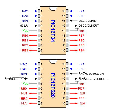
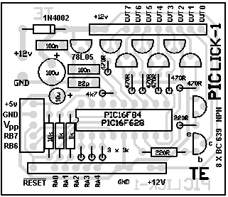
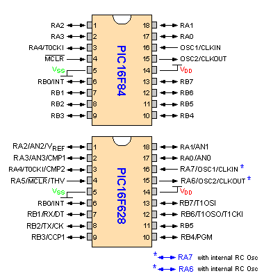
The "building block" for a PIC16F628. The 4MHz oscillator
can be external:
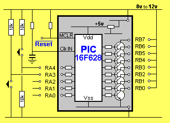
The "building block" for a PIC16F628. Using the 4MHz RC oscillator inside the
chip:
If you fit a PIC16F628 chip, you can use the RC oscillator inside the chip (4MHz
or 37kHz - see 14.2.6 of PIC16F628.pdf ) or the external RC 4MHz oscillator
components (4k7 and 22p) on the PC board. The oscillator components on the PC
board do not have to be removed when using the internal oscillator. The small
current delivered by the 4k7 resistor in the RC oscillator will not damage the
chip. It just represents wasted current.
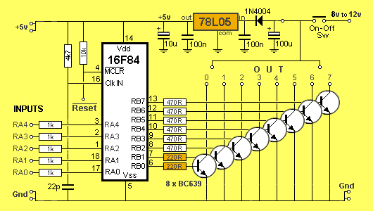
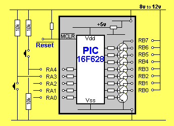
The 5 input lines are protected with 1k buffer resistors and taken to an
"in-line" connector-strip.
The 8 lines of port B are buffered with 1 amp driver transistors and taken to
another connector-strip.
A Reset Pin is also on the PC board. When it is taken LOW, the chip resets. It
is held HIGH via a 10k resistor.
This module does not allow the full in/out capability of each line but it is
miles ahead of anything available on the market for a similar price.
In fact the closest modules are twice the price, have less input/output
capability, run at one-tenth the speed and have less area for a program.
The advantage of our design is it does not have any "overhead." It does not
have any propriety software or hardware that you have to buy. You can take
the chip out of the module and place it directly into a project you have
designed, and it will run immediately.
The microcontroller runs at 1 million instructions per second and this is very
important when you are working on timing intervals, for displays and sounds,
etc.
Programming the chip is carried out "by hand" at machine-code level using
instructions that are able to be read by the microcontroller, and also by
humans. Each instruction consists of letters and numbers that humans can
recognise and is called a "mnemonic." (You can also use any other programming
language if you wish, but we will only be dealing with "hand-assembly.")
Machine code may be slow and laborious, but when you take advantage of our
Library of Routines, and examine the experiments we have presented, you
will be able to go to our "Copy
and Paste" file and put the code into your program to create all types
of effects.
There are a number of sites on the web to help you write assembly programs but
they tend to complicate the job rather than simplify it. I have tried them and
found them to be absolutely impossible to use.
The author has opted for machine code assembly, not because I am a masochist,
but because it is the only way to learn the instructions and achieve a program
of the complexity of the ideas we have presented in some of your projects. Two
games on this site are examples.
To give you some idea of the capability of a 1,000 instruction program in
machine code, the first 4-level chess game was written for the early version of
the Z-80 in 1k of memory! The PIC chip has instructions with more than twice the
power . . . imagine what you can achieve! But don't forget,
the chess game was not written in simple "linear programming mode." The routines
were very clever algorithms. Our programming approach is much simpler and is
called "linear programming." Basically it means the micro will be advancing down
the program and exiting a sub-routine with a solution.
Another reason for choosing machine code is fault finding. By viewing the
program you can see exactly what the micro is accessing and it is much easier to
"hunt down the fault."
MPLAB has a debugging program and a single-step feature that shows the
contents of each register (file) after an instruction.
It has some capability at finding a fault. But don't hold your breath. It
doesn't solve problems for you.
It's handy to see the contents of W and the result of an instruction as well as
where the micro is jumping to, but it is very complex to set up and use.
The author has opted for a much better approach of inserting a set of
instructions at a particular location and outputting the contents of a file to
an 8-LED display. Its a faster approach and shows what is really happening. You
can use the 8 LEDs on the PIC LAB-1 for this.
The other advantage of our method of producing a program in Machine Code is
portability.
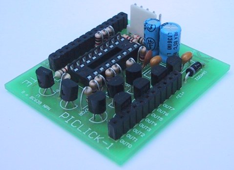
Once you get an idea working on PIC LICK-1, the circuit can be
transferred to a new PC board at the lowest cost.
There are no unnecessary chips and no propriety software to buy or rent. All
the software is FREE.
In the author's opinion, it's the ONLY way to do things.
I can see quite clearly why this type of development-system has not been done
before. There is no monetary rewards to the designer.
But that's not our intent.
Ours is EDUCATION.
If, in the process, we create employment, business opportunities and ideas for
exam projects, our goals have been achieved.
All our projects for the PIC chip can be classified as "tools." They
help you design and develop ideas in the micro world.
They are "building blocks," or "modules," to help create a design.
And that's why we called it the PIC LICK-1.
It licks anything the author has seen, in - price - capability - and speed.
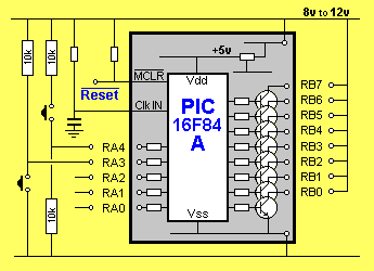
In simple essence, the board is a PIC16F84A with a full port of high-current
drive-lines and a set of 5 buffered inputs.
The following diagram shows the input and output pins we are using in this
module: