| These projects have all been
designed by Talking Electronics and they all have a purpose . .
. they show you how to make interesting things. |
When you are building lots of circuits and using surface-mount LEDs,
there are many times when you have to test a LED to determine the
cathode and identify the colour.
You may also need to compare the brightness as some LEDs are TOO BRIGHT
and others are very weak.
I have even had the case where one end of a surface mount LED was not
soldered correctly and did not illuminate. I had to determine if the LED
or the joint was faulty.
That's why this little project was born.
The tester delivers only about 5mA to 7mA and this will help compare
high bright LEDs from poor-quality LEDs and also any LEDs that have been
damaged due to over-heating/soldering.
One of the big problems with surface mount LEDs is their susceptibility
to damage when being soldered. They are more-sensitive than transistors!
I have never damaged a transistor but some LEDs fail after the best
attempt at soldering.
That's because the light-emitting chip is only a millimeter from the
lead being soldered.
This tester will identify all these problems and it only costs a dollar.
Some of the old LED testers only tested loose LEDs with a current of
1mA, 10mA and 25mA, but this tester will test LEDs in-circuit as well as
surface mount LEDs.
This is the first handy piece of TEST EQUIPMENT for LEDs and there will come a
time when you wish YOU HAD IT.
The tester also has two more features.
It will test a shorted LED and continuity of tracks.
The LED on the tester will illuminate when the probes
touch each other and this proves the batteries are connected.
This feature can also be used as a continuity tester and will also
illuminate LEDs very faintly through the driver-resistors on the circuit
you are testing. So, it has many uses. Just add it to the range of TEST
EQUIPMENT designed by Talking Electronics and you will be ready for
designing and testing all sorts of projects.
Digital Multimeters (DMM's) will illuminate all types of LEDs (with positive
coming out the positive lead) but analogue meters using a single cell
will not illuminate any LEDs. But they will not illuminate
two LEDs in series and many of the projects we design have two LEDs
making a segment of a 7-segment display.
The earth lead is negative and the tip of the probe is positive.
That's why you need all types of test equipment.
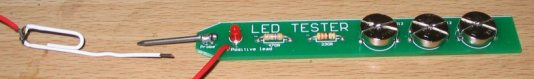
THE CIRCUIT
LED TESTER CIRCUIT
The circuit is very simple. It is just a 4.5v supply with a LED and
resistor in series. When the two probes touch they complete the circuit
and the "test LED" will illuminate. When the probes are across a LED,
only the LED being tested will illuminate. If the "test LED"
illuminates, the LED being tested is shorted.
When a LED on the PC board is illuminated, it will drop between 1.7v and
3.6v due to the characteristic voltage drop across the LED (according to
the colour). This leaves only 0.9v to 2.8v for the voltage across both
the 470R and 330R resistors, as they are in series. Since both resistors
are about the same value, the voltage across each resistor will be about
1.4v and this is not sufficient to illuminate the red LED. A simple but
clever way of turning off the red LED when a LED is being tested. It
only turns ON when a short-circuit is present.
This tester can also be used to test continuity.
It was used recently to determine the connections on a PC board from a
surface-mount 8-pin PIC chip to the 5 programming pins. The LED on the
tester illuminated when connected to the ends of a track. The adjacent
pins were also tested to see if any tracks were shorted to other tracks.
Just another use for this handy tester.
CONSTRUCTION
A kit of components is available from
Talking Electronics.
All the components are included in the
kit
and everything is identified on the board.
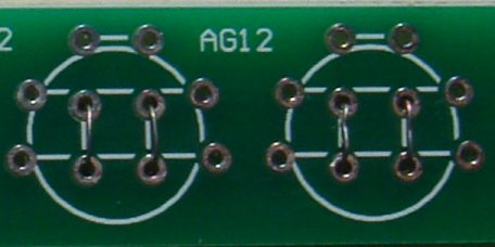
Fine tinned copper wire is fitted through the centre holes to make
contacts for the negative of each cell. These wires are carefully
soldered and the ends trimmed close to the underside of the board.
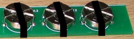
A cell is then placed over these wires and held in place with two wires
over each cell.
Here is a close-up of the tinned copper wire holding the cells in
place. The wires at the top of the cell use thick tinned
copper wire.
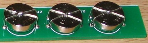
The cells are then held tight by drawing the two wires together
and joining them with a tiny dob of solder. They must not
move or they will lose contact.
Finally, each cell is held in position with a band of heatshrink:
Shrink the plastic with a cigarette lighter, but do it quickly so you
don't get the cells hot.
PARTS
LIST
$2.50
plus
$4.00 post
Order
a kit
|
1 - 330R resistor
1 - 470R resistor
1 - 3mm red LED
1 - 20mm nail for probe
1 - paper clip for earth lead
(or black alligator clip)
1 - 30cm black hook-up wire
3 - button cells - AG12
10cm tinned copper wire
30cm fine tinned copper wire
20cm very fine solder
3 - bands of heatshrink
1 - LED Tester MkII PCB |
|
There is a certain amount of skill required to design a circuit but a
lot of skill to simplify it.
There are lots of transistor tester circuits on the web and they all do
the one thing - identify a PNP or NPN transistor. Some provide the gain
and even the maximum operating voltage but in most cases we only want to
know the c, b, e pin-out and if the transistor is NPN or PNP.
That's what this tester does.
It lets you know the pin identification.
And, amazingly, it only uses a few components.
The secret is the transformer.
It's a flyback transformer that produces a high voltage when the
transistor switches off and this voltage is used to illuminate a single LED
for the PNP transistor and
2 LEDs for the NPN transistor. The two LEDs in series are used to
produce a voltage greater than 1.7v + 2.3v = 4v so the 4v can be used to
illuminate a white LED placed on the "Test LED" pins.
The project uses a single 1.5v cell and this voltage is below the 1.7v
needed to illuminate a red LED so no power switch is required.
There is only one trick to get the circuit working.
The phase of the transformer winding must be correct to get the circuit
to oscillate.
Both windings are 40 turns so it does not matter which
winding is used for the primary or which is used for the feedback. The feedback winding could
be a small as 10 turns but 20 turns or more is guaranteed to get the
circuit to work. But if the feedback
winding is not connected around the correct way, the circuit will not work.
There is no danger of excess current when the feedback winding is
greater than required, it just produces a very brightly illuminated LED.
You can learn a lot about the effect of one winding of a transformer on
another in this air-cored example by slowly bringing the two
windings together to see the circuit start to work.
When the flux density is very low, an air cored transformer is just as
good as iron or ferrite cored and when the current is turned off
very quickly in one of the coils, it produces a collapsing flux that cuts the
turns of all the coils and produces a high voltage in them of the opposite
polarity.
This is the voltage that illuminates the LED because the supply is only
1.5v and it is not capable of doing this. Thus we can prove it is the
transformer that increases the voltage. In fact the voltage is high enough to illuminates two LEDs in series.
If the LEDs are removed, the output peaks at 8v and operates at 700kHz.
The LEDs have a very fast response time and will detect the energy from
the 700,000 spikes per second.
The kit might cost only a few dollars but the experience gained by
experimenting with the two coils is invaluable. By bringing the coils
close to each other you will be able to see the point when the circuit
starts to operate.
This has never been covered before.
Most experiments are done with ferrites cores and you don't get to
understand the fact that air can transfer flux. This is especially
important with very high frequency circuits where the coil is always air
cored as ferrite does not have any advantage over air due to the losses
at high frequency.
The experiments with the coil have to be separate to constructing the
project as we will be concentrating on fitting the coils in the quickest
and easiest way.
This project will also detect the leads of a Darlington transistor
THE CIRCUIT
TRANSISTOR TESTER CIRCUIT
The circuit is very simple. It is just a 1.5v supply driving two
separate oscillator circuits.
You fit an NPN or PNP transistor into one of the circuits with the leads
around the correct way and the LED or LEDs will illuminate.
The 1k5 resistor limits the current into the base so the feedback
winding can produce a voltage that adds to the supply voltage and turns
the transistor ON harder to produce part of the cycle.
The operation of the circuit is quite complex because it involves the
action of a transformer and this is always
quite complex.
When current flows through a single turn of a coil, it produces magnetic
flux and this flux flows around the wire so that it all comes out the
centre of the turn. When more turns are added, the density of the flux
increases as each turn adds more flux.
The supply for this project is from a battery and it produces flux
called STATIONARY FLUX when a coil is connected to a voltage called a DC
supply.
But when it is initially connected to a DC supply, the flux
gradually builds up from zero to a maximum.
During this time the flux is called EXPANDING FLUX. This takes only a few
microseconds to occur.
When the coil is removed from the DC supply, the magnetic flux collapses
and it is called COLLAPSING FLUX.
Thus we can get 3 different types of flux from a DC supply.
When the flux collapses, it cuts all the turns of the coil and produces
a voltage in each of the turns that is opposite to the applied voltage.
In addition, this flux collapses very quickly and the voltage produced
is much higher than the applied voltage.
Finally, there is one more important fact you need to know about
magnetic flux.
When the flux is expanding or collapsing, it cuts the turns of the other
coil in the circuit and produces a voltage in the turns.
BUT when the flux is stationary, it does NOT produce any voltage in the
other coil. It is only EXPANDING or COLLAPSING flux that induces a
voltage in a second coil. The first coil is called the PRIMARY coil and
the other coil is called the SECONDARY COIL or FEEDBACK coil.
This means the PRIMARY coil produces a voltage in the FEEDBACK WINDING when the
PRIMARY is connected and when it is removed, but when it is fully connected
and producing STATIONARY FLUX, the FEEDBACK WINDING is not producing any
voltage.
This is the secret behind the operation of the transformer and you do
not know the magnitude of the voltage produced by either of the coils
until you build the project.
On top of this, you do not know how fast the circuit will oscillator
until it is built. These are all characteristics of the coil, battery
voltage, value of resistor, type of transistor, layout and many other
things. We are not going onto any of this as you can see the result and
measure the frequency, after you assemble everything.
The two coils of wire makes the circuit
a very complex arrangement that needs a high degree of understanding to
see how it works. We will try to simplify everything by getting you to
build the circuit and take measurements.
Two separate circuits are needed because an NPN transistor needs a
positive voltage on the base while an PNP transistor needs a voltage
that is less than the emitter.
Combining the two circuits would need a switch to change the positions
of the coils and a coil of wire is simpler and cheaper to add to the PC
board.
You can increase the brightness of the LED by placing a 100p to 4n7
across the 1k5 resistor. This changes the waveform from 8v to 7v but
increases the frequency to more than 1MHz and the width of the spike is
increased.
The capacitor effectively stops some of the spike being lost or being
driven into the 1k5 resistor and now turns ON the transistor more so a
greater current flows. This current produces a healthier waveform when
the coil collapses and delivers more energy to the LED.
The frequency increases because the transistor turns ON faster.
CONSTRUCTION
A kit of components is available from
Talking Electronics.
All the components are included in the
kit
and everything is identified on the board.
The only fiddly job is making the two transformers.
This is the last job. Make sure all the other components are fitted to
the board before making the coils.
Fit the NPN transistor to the board.
Wind 40 turns on a pen or shaft 12mm dia (0.5in) and make sure the shaft
is tapered so the coil can be easily removed.
If the shaft is parallel, add a match or the lead of a resistor to the
diameter and wind over this at the same time. Remove the wire and the
coil will become lose and easily removed.
Before you remove the coil, twist the two ends together three times and
cut the leads short.
Make 4 identical coils.
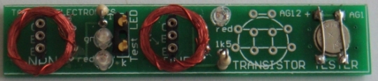
Place two coils on top of each other and keep them together by winding
the 0.25mm wire around them as shown in the photo above.
Do not solder the ends of this wire together as this will produce a
"shorted turn" and the transformer will not work.
Tin the 4 leads and fit two of the leads of one coil to the board.
Poke the other two leads down the holes in the board and the two LEDs
should illuminate because the project is COMPLETE.
If the LEDs do not illuminates, reverse the two leads.
When the LEDs illuminates, you can solder them in position.
Carry out the same procedure with the PNP transistor.
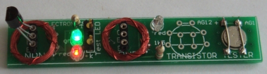
Here is a photo of an NPN transistor fitted to the tester and
illuminating the red and green LEDs. The LEDs are very bright because
HIGH BRIGHT LEDs are included in the kit.
With these two LEDs illuminated, you can test an individual LED,
including white LEDs, by fitting it to the 2-pin component header in the
middle of the board. The two LEDs will go out and the LED under test
will illuminate when it is fitted around the correct way.
The cell is held tight by soldering two wires across the top and
bottom when it is in position.
No on-off switch is needed because the battery voltage is lower than the
voltage needed to activate any of the LEDs. The unused
cell-position on the board is designed for a AG12 cell, just in case you
do not have one of the very small AG1 or AG4 cells. Only 1 cell is
needed.
Transistor Tester
PARTS
LIST
$4.00 plus
$4.00 post
Order a kit
|
2 - 1k5 resistors
2 - 3mm red LED
1 - 3mm green LED
4m - 0.1mm enamelled wire for coils
1 - 20cm 0.25mm enamelled wire around coils
2 - 3-pin machine pin sockets
1 - 3-pin component header
1 - NPN transistor
1 - PNP transistor
1 - button cell - AG1 or AG4 or AG12
1 10cm 0.5mm tinned copper wire
20cm very fine solder
1 - Transistor Tester PCB |
|
|
LED TORCH
also
called
Joule Thief |
LED TORCH - JOULE
THIEF - INDUCTOR TESTER
Kit of components $3.00 plus $4.00 postage
An
equivalent IC (chip) has come on the market for 10 cents and it
is a better chip.
Here is the circuit for QX5252F:
Using 220uH, the circuit takes 13mA an illuminates 2 white LEDs
very brightly.
Using 100uH the circuit takes 30mA and the LEDs are really the
same brightness.
Using 33uH the circuit takes 80mA and the LEDs are just about
the same brightness.
Obviously the 220uH creates the most efficient circuit.
Here
is the prototype:
The kit
comes with a PCB, all parts: QX5252 Chip, tactile switch, 1.5v
button cell, tinned copper wire for cell and heatshrink for
cell-cover, 100uH inductor, very fine wire and 1M to make your
own 100uH, 2 machine pins and length of fine solder, but only 2
LEDs and not the change-over switch.
All for $7.00 posted.
Email
Colin Mitchell for
details on buying the kit.
The
prototype has been built on Matrix Board and shows the
change-over switch used to test different LEDs. You will get
the Printed Circuit Board in the kit that has been generated
from the layout. This is the easiest and simplest way to make a
PCB and avoid any mistakes.
The inductor has been fitted via machine pins and it can be
removed and different inductors fitted to see the results. A
machine pin is hollow and allows to poke the ends of a conductor
into the pin and it will make contact.
The current taken by the circuit changes according to the
inductance and this will enable you to compare inductors and
even find the value of an unknown inductor.
You need to use one, two or three known inductors and make a
table of the inductance and current taken by the circuit.
The current may or may not be linear but we measured inductors
from 33uH 1,000uH and recorded currents from 80mA to 2.5mA.
This enabled us to measure unmarked coils.
HOME-MADE
INDUCTOR
One more feature of this project is to wind your own inductor
and see if it is effective as the 100uH supplied in the kit.
The kit comes with fine wire and a 1M resistor.
Wind 250 turns on the resistor very carefully and as you come to
the end of the winding, you can criss-cross the wire over the
other turns to keep them in place.
Leave at least 4cm of wire at the beginning and end.
Now heat the wire very close to the body of the resistor with a
hot clean soldering iron that has been fully tinned. The wire
will get tinned very close to where it comes from the winding.
Now wind 5 turns around the wire coming from the resistor and
solder it in place. Break off the wire.
Do the same with the other end.
Fit your home-made inductor and the LED should be as bright as
the 100uH.
Measure the current across the switch. It should be about 32mA.
The voltage is being converted from 1.5v to 3.5v and each LED
will get slightly less than 6mA by the time you take the
efficiency of the circuit into account.
This
project will teach you 3 things:
The number of turns to create 100uH inductor, testing different
inductors, testing different LEDs and determining the value of
inductance by measuring the current.
|
LED Torch
PARTS LIST
$7.00 incl postage
Email
Colin Mitchell for
details
on buying the kit. |
|
The
LED Torch - Joule Thief
project comes with a PCB, all parts: QX5252 Chip,
tactile switch, 1.5v button cell, tinned copper wire
for cell and heatshrink for cell-cover, 100uH
inductor, very fine wire and 1M to make your own
100uH, 2 machine pins and length of fine solder, but
only 2 LEDs and not the change-over switch. All for
$7.00 posted.
Email
Colin Mitchell for
details on buying the kit. |
|
|
Necessity is the Mother of Invention.
The best ideas come from a personal need.
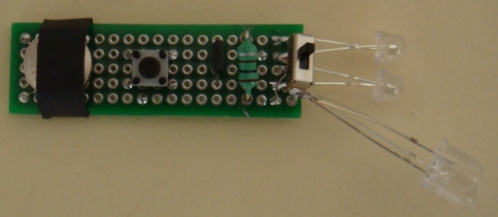
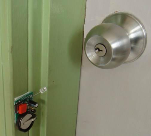
The front door at the authors house is dark at night-time and it is
difficult to find the key-hole.
This project solves the problem by shining a light on the problem
when the button is pressed.
The circuit illuminates a LED for about 10 seconds so you can fit
the key.
The circuit gradually dies and consumes absolutely no current when
not being used.
Although one cell will illuminate a white LED when it is new, this
is not reliable so we use 2 coin-cells and a constant-current
circuit so the LED maintains the same brightness over the full life
of the cells.
The current is less than 10mA and the LED we supply on the kit has
very good brightness at this current.
THE CIRCUIT
KEY-HOLE LIGHT CIRCUIT
The circuit is very clever. 6 components do TWO things. They create
a time-delay and provide a constant-current for the LED.
The time delay consists of the 100u and 100k resistor. The constant
current consists of the two diodes and 15R resistor. The transistor
is the amplifying device.
When the button is pressed, the 100u is instantly fully charged and
this puts a voltage (and current) on the base of the transistor. The
maximum current will be 50uA and the gain of the transistor will
increase this 200 to 400 times to produce a maximum of 50 x 200 =
10mA to 20mA collector current. This is sufficient for our
application.
The transistor turns ON when the electro is charged and current
flows through the 15R resistor. At the moment we do not know how
much current flows through the 15R resistor, but there are two facts
we know about the section of the circuit we are analysing.
1. The voltage on the base cannot rise above 0.7v + 0.7v due to the
two diodes, and
2. The voltage across the base-emitter junction is 0.7v when the
transistor is turned ON.
This leaves exactly 0.7v for the voltage across the 15R resistor and
as the current increases, the voltage across the 15R resistor
increases to 0.7v.
If the current increases further, the voltage across the 15R would
increase to 0.8v and only 0.6v would be available for the
base-emitter junction. This means the transistor would be turned off
and this is NOT POSSIBLE. Thus the emitter voltage NEVER rises above
0.7v.
That's why we call this a CONSTANT-CURRENT circuit.
The current passing through the emitter resistor is the same current
passing through the collector-emitter terminals of the transistor
and also through the LED.
It can be found from the following: V=
IR.
0.7 = I
x 15
I
= 0.7/15 = 5mA
The actual voltage developed across the diodes and base-emitter
junction is slightly different to 0.7v and the current was measured
at 9mA.
This constant current will flow while the 100u has a voltage of
about 6v and will decrease slightly as the electro discharges.
The circuit takes a very small current from the 100u to drive the
base of the transistor and the electro gradually discharges.
When it reaches 1.4v, the circuit turns OFF completely and NO
CURRENT is taken from the coin cells.
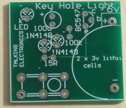
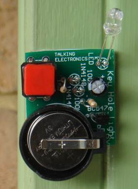
CONSTRUCTION
A kit of components is
available from
Talking Electronics
for $4.50
All the components are included in the kit and
everything is identified on the board.
|
PARTS LIST
$4.50
plus $4.00 post
Order a kit |
1 - 15R resistor
1 - 100k
1 - 100u electrolytic
2 - 1N4148 diodes
1 - BC547 transistor
1 - 5mm super-bright white LED
2 - coin cells - CR2016 (lithium cells)
1 - coin cell holder
1 - large tactile push button
10cm very fine solder
1 - Key Hole Light PCB |
|
There are many sound chips on the market (at very low cost) and
they produce very interesting sounds. The UM3561 is one of these
IC’s.
It can be used in many different applications, including model
railway layouts, to add realism to some of the dioramas.
It contains 4 different siren sounds and these can be accessed
by taking a “control line” (pin) either HIGH or LOW.
When no pins (lines) are “controlled,” (taken HIGH or LOW) the
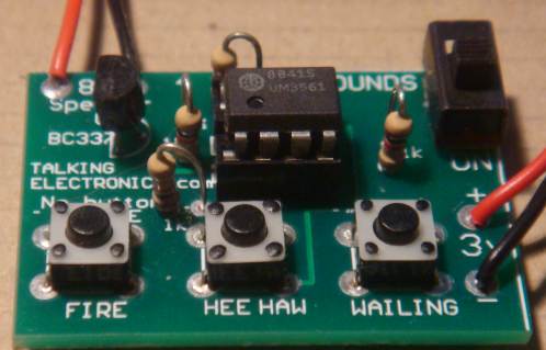
chip produces a POLICE CAR SIREN. When pins (called SEL 1 and
SEL 2) are taken HIGH or LOW, it produces FIRE(ing) of a MACHINE
GUN (not a fire engine sound), HEE HAW or a WAILING ALARM.
These sounds can be added to an alarm project or a toy for a
child.
The output is quite loud on 3v (with a small speaker) and will
be very annoying when connected to a power amplifier driving a
horn speaker.
When used as a house alarm, no Select lines are connected HIGH
or LOW and the chip produces POLICE CAR SIREN when activated.
The chip is turned ON by the house alarm and fed into a power
amplifier driving a horn speaker.
This project is designed to test the chip and can be added to a
toy truck where a child will find it entertaining to change the
sounds and annoy everyone within 10 minutes.
The chip operates on 3v and the supply must not be more than 5v.
The driver transistor is an external component (shown on the
circuit as BC337) and it can be connected to a higher voltage
(via a speaker as the LOAD) as this will not affect the voltage
on the chip. (A BC547 does not produce a loud sound. It does not
have sufficient collector-current driving capability – a BC337
or BC338 is needed.)
The chip is designed to produce POLICE CAR SIREN when it is
turned ON as Select line 2 is internally pulled LOW. When this
line is taken HIGH, the chip produces the sound of a MACHINE GUN
FIRING.
The other two sounds are a WAILING SIREN and HEE HAW from Select
line 1.
Just in case two switches are pressed at the same time, two 1k
resistors (you only need one 1k resistor) have been added to
prevent a short-circuit across the supply rail. If they are both
pressed, HEE HAW is produced.
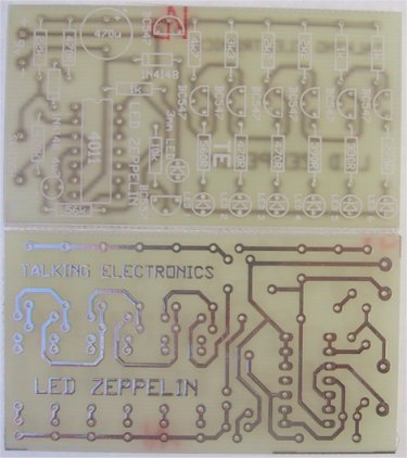
The printed circuit board is very simple and you can copy the
layout on Matrix Board and join the lands with fine tinned
copper wire. Matrix Board is a set of holes spaced at 0.1 inch
apart and can be punched or drilled on plain board or have
copper or tinned lands to make soldering easy. Do not use STRIP
BOARD as the strips have to be cut and this is a very messy job.
Note: The PC board shown in the diagram is double-sided with 3
tracks (called traces) on the top. You will need to use fine
enamelled wire, if you are making your own single-sided board.
There are many other SOUND CHIPS with siren sounds, animal
sounds and train sounds, on the market. They are all very
realistic and can be used for experimenting or adding to a
more-complex project.
The barking dog IC is very realistic and the 4 train sounds IC
can be added to your layout for a very realistic effect.
The author has experimented with all these IC’s and used them in
many different projects. The chips are very complex and you
cannot get the same sound without investing a lot of time and
effort and then you will realise the SOUND CHIP is the answer.
You can also get some very interesting chips in greeting cards
and also in small toys – so look in different shops and you will
be surprised.
Experimenting with these chips is great fun and you will learn a
lot when you interface (connect) them to amplifiers and switches
to get them to work and then you can give them to one your
younger family members.
THE CIRCUIT
4 SIREN SOUNDS
CIRCUIT
CONSTRUCTION
A kit of components
is available from
Talking Electronics.
All the components are included in the kit
and everything is identified on the board.
|
PARTS LIST
$6.50
plus
$4.50 post
Order a kit |
3 - 1k resistor
1 - 330k
1 - BC337 transistor
1 - UM3961 IC
1 - 8 pin IC socket
1 - 3v AAA cell holder
2 - AAA cells required
3 - tactile push buttons
1 - SPDT slide switch
1 - 8R mini speaker
10cm very fine solder
1 - 4 Siren Sounds
PCB |
|

A game of skill
LED
Zeppelin is a game of patience. It's like getting a kite into
the air. It goes up slowly but the slightest mistake will bring
it down like a lead balloon.

The name of our game, LED Zeppelin, is a play on words. It comes
not from the pop group of the same name but from Graf Von
Zeppelin, a German who invented the first rigid air ship in
1900.
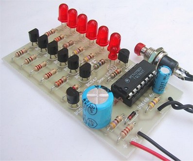
The association fits perfectly. The game consists of six LEDs
and an indicator LED that flashes at a rate of about 2 cycles
per second. A push button is the "Operations Control" and by
carefully pushing the button in synchronisation with the
flashing LED, the row of LEDs will gradually light up.
But the slightest mistake will immediately extinguish one, two
or three LEDs. The aim of the game is to illuminate the 6 LEDs
with the least number of pushes.
|
A close up
of the completed LED Zeppelin |
HOW THE CIRCUIT
WORKS
The circuit consists of a three-inverter CMOS clock-oscillator
driving Q8 that flashes the LEDs on and off. The other output
from the oscillator is used to charge up the 470u electrolytic
C2, via R3.
The output from pin 3 is in the form of a square wave only
slightly less than the supply voltage and is about 7.5v to 8v in
amplitude. The frequency at which the circuit works is governed
by R1, R2 and C1 and is approximately 2Hz. Charging of the 470u
electrolytic is exponential so that initially the voltage
increments on the capacitor will be high when it is beginning to
charge. Each time the button is pressed a small amount of energy
is fed into C2. This voltage appears at the base of Q1. Q1 is
connected as an emitter-follower and the same value of voltage
will appear at the emitter, less 0.6v base-emitter voltage drop.
This voltage is then fed to the base of six transistors Q2 to Q7
that drive LEDs 1-6 via current limiting resistors. Each of
these transistors will turn on according to the voltage on the
470u electrolytic.
When the voltage rises to 0.6v, Q1 will turn on. For Q2 to turn
on its base must be .6v higher than the emitter. Q2 has a
forward-biased diode in its emitter and the voltage drop across
it will be .6v. The base of Q2 must be .6v above the emitter,
making it .6v plus .6v or 1.2v This means the voltage on C2 will
be .6v plus .6v plus .6v or 1.8v for the first LED to be fully
lit.
The emitter of Q3 is connected to the base of Q2 so that a
further .6v will turn it on. At each successive .6v rise the
next transistor in the chain will turn on until finally Q7 will
turn on. This transistor drives the top LED that is the
highlight of the game. When you have LED 6 pulsing you really
feel a sense of achievement.
Should the button be pressed when the oscillator is low, diode
D1 is forward biased and the charge on C2 will rapidly discharge
through R4. Since the voltage increments become smaller as the
470u becomes fully charged, to light the top LED requires
significantly more pushes than LEDs 1 and 2.
If, however, the button is pushed too long, the discharge will
be greatest when the capacitor is nearing full charge and an
error here will lose the gain made by many pushes. This is where
the skill of the game comes in. The charging of the capacitor is
"out of phase" with the flashing of the LEDs. This means the
button must be pressed when the LEDs are extinguished. To turn
the game off or restart it, push the button when the LEDs are
lit. This will remove the charge on C2 and eventually every LED
will go out.
TERMINOLOGY
Some of the terms used in our articles may be new to some
readers.
We have used universally recognised symbols and standard
component identification.
The letters LED stand for Light Emitting Diode.
A small LED is 3mm or 1/8", a large LED is 5mm or 1/4".
Most of the circuits in our projects use a general purpose NPN
transistor. We have specified BC 547 or 2N 3904 or 2N 2222 for
this, however there are many other types that will work equally
well.
For the PNP general purpose transistor we have specified BC 557
or 2N 3906, however there are many other equally suitable types
too. When we specify this type of transistor we also infer its
characteristics are not important. It is very frustrating to
find on odd type of transistor specified in a project. You
immediately think it has special characteristics and start
searching through catalogues for a supplier. Most
battery-operated projects use the most-common cheapest,
transistor available in your country.
|
PARTS
LIST |
1 - 270R
1 - 330R
1 - 390R
3 - 470R
3 - 1k
2 - 2k2
1 - 3k3
1 - 4k7
1 - 10k
1 - 22k
1 - 56k
1 - 470k
1 - 4u7 16v PC mount electrolytic
1 - 470u 16v PC mount electrolytic
7 - BC 547, or 2N 2222 transistors
1 - BC 557 or 2N 3906 transistor
1 - CD4011 IC
1 - 3mm (1/8") red LED
6 - 5mm (1/4") red LEDs
2 - 1N 4148 signal diodes
1 - 14 pin IC socket
1 - push button
1 - battery snap
1 - LED Zeppelin PC board |
CONSTRUCTION
All the components are mounted on the Printed Circuit Board.
Follow the layout diagram for the identification of each part.
You will notice all the components are placed neatly on the
board with Q2 - Q7 fitted the same way around and all LEDs the
same way. For the transistors, the overlay shows the shape of
the case and this allows it to be fitted only one way around.
This only refers to BC 547. Refer to the transistor pinout for
other types.
Both electrolytics are identified with their
positive lead on the overlay. This lead is the longer of the two
leads on a single-ended electrolytic and if both leads have been
cut the same length, you will have to refer to the stripe on the
side of the case for the negative lead.
The IC socket is next and is fitted so that the cut-out at the
end of the socket goes over the shape on the overlay.
The IC is inserted into the IC socket so that the cut-out at the
end of the chip fits over the cut-out at the end of the socket.
The last two items to connect are the two wires for the
game-switch and the battery snap. Check all soldering and the
orientation of the transistors. It is a wise to connect a
milliammeter in one battery lead before switching on a project
for the first time to check if a short-circuit is present or
excessive current is being drawn.
HOW TO PLAY
The 3mm (1/8") LED begins to flash when the battery is
connected. This indicates the flash rate. To start the staircase
of LEDS flashing, push the switch a number of times, (when the
LED is extinguished). After a few pushes you will see the first
LED flash faintly. Keep in step with the off periods and you
will gradually increase the illumination. The rest is up to you.
The LED ZEPPELIN game can be played a number of ways. The most
popular way is to count the number of pushes required to get the
top LED flashing with reasonable brightness. The player with the
least number of pushes wins.
Another variation is to cover the six LEDs with black tape
leaving just the indicator LED flashing. The object of the game
is to see how many LEDS can be set flashing with a certain
number of pushes. Start with 50 pushes per player. Push the
button 50 times then remove the tape and read your score. You
can make certain adjustments such as 3.5 or just over two LEDs
flashing.
When used competitively like this, the game provides a means of
assessing your reflex time and co-ordination. |
|
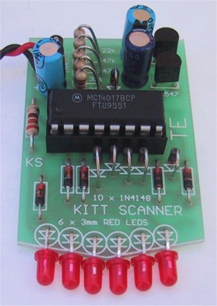
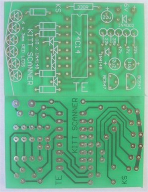
KITT SCANNER
A REALISTIC
SCANNER FOR KNIGHT RIDER MODELS
Most people are familiar
with the adventures of a certain black Trans-Am with 5000 Megabit
memory.
This car started life as emotionless and argumentative but by the
time it smashed its way through the first episode, everybody wanted
to own it.
MPC released a model of the Knight 2000 in 1983 and the first
shipment sold out before I could get my hands on one. Thirty shops
later.. success!
The, MPC model is moulded in black plastic with dark tinted windows
and a few chrome parts. The car is supplied with a red tail light
but unfortunately the scanner is part of the black moulding.
To make the model more of an attention-getter, I decided to put a
working scanner into it.
This project is the results of my design.
The scanner is made on a small PC board and mounted under the bonnet
so that the LEDs shine through a piece of red plastic glued in place
of the black plastic moulding.
The turbo V8 engine, drive shaft and exhaust system must also be
removed to make room for the PC board.
The first comment you may make is KITT has 7 lights and the scanner
only 6. We could only design a simple circuit for 6 LEDs and
unfortunately only 6 would fit.

HOW THE CIRCUIT WORKS
The circuit consists of two building blocks. The first is a
square wave oscillator made up of two transistors in a
multivibrator arrangement and the second is a CD 4017 decade
counter IC.
The multivibrator contains two extra components to speed up the
waveform and make it acceptable for all brands of 4017's. Unless
the output has a very fast rise and fall characteristic, some
4017's fail to operate properly. They either do not work at all
or jump two or three outputs, losing the scanning effect.
The two speed-up components are the signal diode and 39k
resistor and are essential for reliable operation.
The output of the multivibrator feeds into the CLOCK INPUT of
the chip. From there is goes to a complex counting circuit
inside the 4017. The circuit counts to 10 and only one output is
active (HIGH) during each of the 10 steps.
Initially output pin 3 is HIGH while all others are LOW. After
one clock cycle the second output (pin 2) goes HIGH while all
others are LOW. After the next clock cycle pin 4 goes HIGH etc
through to the 10th output which is pin 11. We could see the
effect of these outputs going HIGH by placing 10 light emitting
diodes on the lines. They would give a 'running light effect'.
Remember this.
We have placed 10 signal diodes on the output of the chip so
that we can illuminate a set of Light Emitting Diodes from one
of two different lines.
Eight of these diodes form four OR gates to direct the
appropriate outputs of the 4017 to the corresponding LEDs. The
remaining two diodes equalise the brightness of the two un-gated
LEDs.
The first 6 outputs operate the diodes in a normal running light
sequence. The clever part comes with output Q6. It is taken to
the 5th LED and this creates the effect of reversing the
sequence. Q7 drives the 4th LED and this continues the reverse
effect until the second LED. The chip has now completed one
cycle and the first output is now turned ON. This illuminates
the first LED to complete the full back-and-forth scan.
Each time the 4017 goes through its run of 10 outputs, the
scanner completes one forward and reverse scan.
This is how the effect is generated. It is the first time anyone
has used the chip in this way and it shows you don't have to
stick to convention.
|
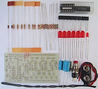
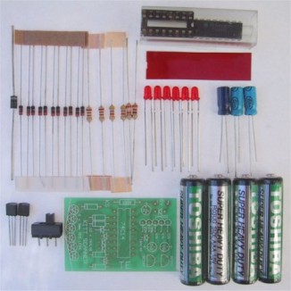
Complete
set of components for the Kitt Scanner |
|
PARTS LIST |
1 - 330R 1/4 watt
2 - 22k
1 - 39k
2 - 47k
1 - 2.2u electrolytic PC mount
1 - 10u PC mount
1 - 22u PC mount
11 - 1N4148 diodes
1 - 1N 4002 diode
2 - BC 547 transistors
1 - CD4017 IC
1 - 16 pin IC socket
4 - 'AAA' cells
6 - 3mm red LEDs
1 - miniature SPDT slide switch
1 - piece of red plastic
1 - SCANNER PC BOARD |
CONSTRUCTION
The SCANNER is
constructed on a PC board which has one end specially shaped to
fit into a plastic model and give the LEDs the radius they need
for alignment against a piece of red diffusing screen.
This end is shaped before any of the parts are fitted, by
cutting the excess from the board with a pair of side-cutters.
After this, the board is finished off with a file.
Refer to the photo before mounting the parts to see how and
where they are placed. Some fit against the board and others are
mounted upright to take up the least amount of space.
Start by inserting the 11 signal diodes. Some of these lay flat
against the board while others are almost upright. The way they
stand (or lay), depends on the distance between the holes and
you will have to fit them as neatly as possible.
The 10 diodes (in a row) face the same way and the single diode
in the oscillator faces downwards.
Next mount the row of 5 resistors and the single resistor which
lays flat against the board. The resistors in the row stand on
END and it is important to get the values correct. They are
clearly marked on the overlay and you can also refer to the
layout diagram in the article.
Next solder the input protection diode to the PC board. This
diode stands on END.
Next fit the IC socket so that pin 1 identification (either a
cut-out or corner missing from the socket) aligns with the dot
on the PC board. This will make it easier to fit the IC
correctly.
The two transistors are fitted so that they nearly touch the PC
board and only a gap equal to the height of a resistor separates
them from the board.
The three electrolytics are mounted so that the positive lead
goes down the identified hole on the PC board. You will notice
the negative lead is identified on the component while the
positive lead is identified on the board. Do not get confused!
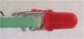
The last components to be mounted are the LEDs. Once you fit
them, they cannot be refitted as the leads will be too short. So
get it right.
The cathode lead is the shortest and this goes directly to the
track-work on the front of the board. It does not pass
through a hole. The anode lead passes over the board and
down a hole where it is soldered in place.
Cut the anode lead as shown in the diagram
below and bend it to 90°. Cut the cathode lead very short and
the LED is ready for mounting. Fit it onto the board and solder
each lead very quickly to prevent damage to the crystal inside
the LED.
This is an unusual way of mounting LEDs but suits our
project perfectly.
There is one thing you must never do. Never spread the leads of
a LED as this will crack the plastic encapsulation and it will
be damaged. There will, however be some slight spreading of the
leads as they are inserted and this is the maximum allowable.
Fit only one LED and check to see if it has been fitted correctly.
Fit the IC and connect the board to a 6v supply. The LED should
blink on/off.
If it doesn't, check the orientation by looking into the body and
noting a large 'cup'. This is the cathode and goes directly to the
underside of the board. Place a multimeter across the LED, with the
project working. The needle should swing up to 1.5v for a brief
period of time.
If it does, but the LED doesn't light, you have possibly damaged it,
either by separating the leads too far or overheating it when
soldering.
If the LED does illuminate, continue fitting the rest until all are
placed neatly in a row.
Make sure they continue the radius of the board so they fit behind
the screen in the car.
Two power leads are soldered to the board and these must be long
enough to reach the rear of the model.
The 4 AAA cells are mounted in the boot and soldered together to
form a 6v battery pack. A small slide switch is placed under the car
to turn the scanner ON.
Now is the time to test the project and watch the effect. You will
find it quite hypnotic. If everything works well, mount the board
up-side-down in the bonnet compartment so that it is parallel to the
ground. Make up a couple of struts to support the board to keep it
in position.
Everything is now ready for the final touches of presentation.
Complete the assembly of the model and make sure all traces of
wiring, batteries and PC board are removed from view.
I know you will be pleased with the effect, but break the news
slowly to your friends. Say "Wouldn't it be nice if we had the real
effect of the Knight Rider scanner!"
Then flick the switch!
IF IT DOESN'T WORK
There are two sections
to this project. If the LEDs do not scan, the fault will lie in
either section. You have to isolate which section is at fault.
Firstly test the multivibrator. Place a multimeter, set to VOLTAGE,
between pins 14 and earth. The needle on the meter should oscillate,
indicating the transistor section is producing a waveform. If this
wave-form is present, the 4017 could be at fault. Check the voltage
on pin 16. It should be rail voltage. Check the voltage on pins 13
and 15. It must be LOW for the chip to count. If the first LED
remains ON, the 4017 could be damaged or the input waveform too low
to clock the chip. Try a new chip.
The next stage is to isolate the chip from the multivibrator. This
is done by isolating pin 14 from the circuit and connecting a jumper
lead to it.
Take this jumper to rail and then to earth. This will produce a full
transition on the clock line and hopefully cause the chip to count.
If this is successful, the incoming clock pulses are TOO SMALL or of
poor quality.
A CR0 would be handy to check the wave-shape but if this is not
available, you can manually clock the chip via the transistor
circuit. Firstly take one base lead to ground and then the other
base lead to ground. While doing this you can measure the voltage on
the collector of the output transistor and note that it changes from
LOW to HIGH.
If the chip does not clock, the fault will lie in the output
transistor. It may not be connected to earth. the diode may be
around the wrong way, or creating a leakage which will inhibit the
amplitude of the output pulse, or the resistor may be the wrong
value. The only other possibility is the transistor. It may be
damaged and thus will not amplify sufficiently.
If the chip jumps LEDs when scanning, the pulse shaper circuit maybe
at fault or the amplitude of the signal is too low for the chip. It
could also be the 4017. Some 4017's have Schmitt trigger circuits in
the input line to reduce the effects of noise. Others do not have
in-built Schmitt triggers. Try a different brand of chip.
If one or more of the LEDs fail to come on, place the multimeter on
the relevant output and watch the needle. If it pulses HIGH/LOW, the
signal is emerging from the chip and the LED will be at fault. (or
the soldering). Try the signal on the other end of the diode. If it
is not present, the diode is at fault or has been inserted around
the wrong way.
If the scanner is running too fast, the electrolytics will be the
wrong value or 'dry'. It could also be due to the wrong value of
resistance in the base lines.
The 330R resistor in the cathode line of the LEDs is a current
limiting resistor to prevent the LEDs taking too much current. Make
sure it is connected to the circuit or the LEDs will not come on.
If you follow these suggestions your scanner should be working
perfectly.
I hope you find it to be a captivating addition to your Knight kit.
|
|
This project is a great way to learn
about FM transmission.
With just a few components you can create your own FM
Radio Station !!! |
This project has been designed to compete with the low-cost
kits on the market. This kit is better than all the rest.
1 and 2 transistor kits are very poor performers and it is
pointless getting a kit that does not perform.
You will be disappointed and think all FM transmitters are
useless.
But that is not so.
You need 3 transistors to get reliable performance.
The first transistor amplifies the signal from the microphone so
you can hear a pin drop.
The second transistor creates the frequency at which the bug
transmits and
The third transistor acts as an amplifier (in the form of a
BUFFER), to separate the oscillator from the antenna, so the bug
does not drift when being held.
The circuit is well-designed and includes an interesting
feature: "SLUG TUNING."
We have used a steel bolt or "screw" to adjust the frequency of
the circuit and it is screwed through the board and into the
coil.
By placing the first two turns close to the board, the end of
the bolt will have an effect on changing the frequency.
This is called a SLUG TUNED COIL and is one of the oldest ways
to tune a radio or transmitter.
The slug is normally ferrite but if you only insert a small
portion, the frequency will shift slightly. If the bolt is fully
inserted, it will freeze the oscillator as the coil will pass
all its energy into the bolt and the circuit will stop
oscillating. But just a small insertion will tune the bug to the
frequency you want.
The approximate frequency on the 88MHz to 108MHz band is
set by expanding or compressing the 5 turn coil and then the
fine tuning is done by screwing the bold from the underside of
the board. As you expand the turns, the frequency increases and
compressing the turns takes the frequency from 88MHz to a lower
frequency.
Designing a good circuit involves a number of points.
The layout of the board is important as well as the choice of
actual component values.
Our is the simplest and best design and has been perfected over
the past 25 years from the sales of over 100,000 kits and 20
different designs.
Talking Electronics was the first company in the world to
produce a kit and attach a free PC board to the cover of the
magazine.
This brought over 30,000 hobbyists into the market of building
their own transmitter and experiencing the clarity of FM and the
enormous range possible with only a few milliwatts of power.
These kits are very easy to build and result in an enormous
achievement with just a few components.
The fun of talking and listening is like having your own radio
station and you can transmit music from one location to another
or use it to talk over a long distance to lots of listeners.
You can use it as a "Radio Mic" at a gathering or a stage
performance.
The clarity is so perfect, you will think the person is actually
in the room.
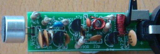
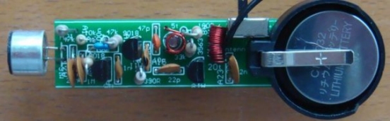
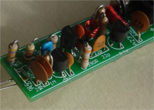
All the parts fit very neatly on the board and the only thing you
have to align is the 5 turn oscillator coil. The leads need to be
bet so they fit down the holes and the coil sits directly above the
screw.
Make sure you tin the leads so the enamel is removed, BEFORE
fitting the coil down the holes.
The 20 turn coil is also pre-wound with 0.25mm wire and it is
easier to tin and fit to the board.
All the parts are in the same position as on the circuit diagram
and this makes it easy to compare the two when trouble-shooting.
The prototype-worked as soon as it was built and this is a
testament to the designs created by Talking Electronics. Over
50,000 FM Bugs have been sold and TE has 20 different types.
This is the cheapest and best and is better than any other $8.00
bug on the market.
The screw tuning is primitive but has been used since the
earliest days of radio.
The input is amplified with a stage and the output is buffered
with a stage.
The three stages create a very sensitive transmitter that can be
handled and it will pick up the sound of a pin dropping on the
floor.
HOW THE CIRCUIT
WORKS
The circuit is very simple but you have to use the right-value
components and put them in the correct part of the circuit to
get the best results.
Many of the circuits on the web contain faults are not very
reliable.
The first stage consists of a single component - the electret
mic. This is actually a FET (Field Effect Transistor) and it has
to have a very small current for it to operate correctly. This
current is delivered by the 47k resistor.
The output is only a few millivolts but the signal is very clean
and the microphone will pick up a pin dropping on the floor.
The output is connected to the next stage via a 22n capacitor.
This value is easy to obtain as a ceramic capacitor and passes
about 20% of the amplitude of the signal. This is sufficient for
the first transistor in the circuit.
It amplifies the signal about 70 times to get an output of
between 70mV and 700mV.
The 22n across the power rails near the microphone prevents
internal feedback in the circuit called "Motor-boating" or
squeal and the 100R combines with the capacitor to isolates the
first transistors from the third transistor.
The second transistor is the oscillator. It gets its feedback
from the 10p capacitor between the collector and emitter.
The transistor turns on via the 47k base resistor and puts a
little bit of energy into the coil and capacitor combination on
the collector.
This is called a PARALLEL TUNED CIRCUIT and the capacitor
gets charged first. The coil initially refuses to allow current
to flow through it but as the capacitor charges, the coil allows
current to flow.
During this time the voltage on the collector falls and this
fall passes through the 10p to lower the voltage on the emitter
and keep the transistor turned ON.
The 10p charges during this time and the transistor turns off
slightly. This reduces the current in the coil and the magnetic
field starts to collapse and produce a voltage from the coil
that is in the opposite direction.
This puts a higher voltage on the collector and this voltage is
passed to the emitter to turn the transistor OFF slightly more.
This continues until the transistor is completely turned off and
it is similar to the transistor being removed from the circuit.
The coil continues to produce a voltage and charges the
capacitor.
This voltage can be as high as 3v or more, depending on the
amount of energy it contains and the amount of energy required
to charge the capacitor to 3v.
The end result is a voltage that can be greater than 6v, however
we are not using this voltage but tapping off the emitter, where
a much smaller voltage is produced.
The emitter waveform passes through the 22p to the output stage.
This a class "A" amplifier and the signal is amplified about 50
times. It could be grater than this due to the effect of the RFC
on the collector.
This is called a RADIO FREQUENCY CHOKE and it has the
effect of storing energy during parts of the cycle and
delivering the energy during the remainder of the cycle.
The end result is a larger output waveform.
If you connect the antenna to the collector of the oscillator
transistor, it will remove some of the energy and change the
frequency at which the circuit works. This is called "drift" and
is very annoying as the reception will be lost.
To prevent drift, we have added the 3rd transistor.
It is called a "Buffer Stage" and is designed to separate the
antenna from the oscillator.
Finally, the 22n across the power rails is deigned to tighten
the rails.
This means the top rail does not move up and down when the
transistor is sending audio.
It helps to maintain the frequency at which the circuit works as
the oscillator is also called a voltage-controlled oscillator
and a change in voltage will produce a slightly different output
frequency.
TUNING
Tuning is the capability of changing the frequency of the
oscillator so the bug transmits on a clear part of the band.
The FM band is completely filled with radio stations from 88MHz
to 108MHz and there is almost nothing available.
The only frequency available in most large cities is 87MHz and
some radios will receive as low as 86.5MHz.
The best type of FM radio for picking up our bug is a manually
tuned radio.
This allows you to get right on top of the frequency of the bug
and achieve the greatest range.
Many of the digitally tuned radios jump in steps of 50kHz or
100kHz and since radio stations have been allocated to these
frequencies, you will be competing with a radio station.
The 5-turn coil and the 47p produces a frequency at the lower
end of the band and screwing the slug (screw) into the coil will
lower the frequency to below 88MHz.
You have to start with the frequency above 88MHz and then
carefully reduce it without losing it below 86MHz.
The range of the transmitter is hundreds of metres with the
170cm antenna supplied in the kit and tuning with a
manually-tuned radio is simple.
Use the "tuning LED" on the radio to indicate maximum reception.
Move the bug further away and retune the radio.
|
Screwing the slug into the coil
reduces the frequency of transmission. |
RANGE
How far will this project transmit?
This circuit was placed at the top of a mountain and transmitted
27km to the hobbyists car-radio when he got home.
This was a line-of-sight transmission and was an ideal "set-up."
We have achieved from 200 metres to 400 metres from a house to a
hand-held radio while walking down the street when there are no
houses blocking the transmission.
Some of the worst conditions are through concrete walls as they
contain mesh reinforcing that almost totally prevents the signal
passing through.
|
|
1 - 100R all 0.25watt
1 - 390R
1 - 10k
1 - 33k
2 - 47k
1 - 1M
1 - 10p ceramic capacitor
1 - 22p ceramic capacitor
1 - 47p ceramic capacitor
1 - 1n ceramic capacitor
3 - 22n ceramic capacitor
1 - 100n monoblock capacitor
2 - 2SC9018 transistors
1 - PN3563 transistor
1 - electret microphone
1 - mini slide switch
1 - 3v lithium coin cell
1 - coin cell holder
1 - 5 turn coil 0.5mm dia wire
1 - 20 turn coil 0.25mm dia wire
1 - bolt
1 - 170cm hook-up wire for antenna
1 - 20cm fine solder
1 -
FM BUG - ST PCB |
|
|
|
PIC DICE
Complete kit $8.50
plus $4.00 postage
Buy a
kit |
This project uses an
8-pin microcontroller to produce a tumbling dice via red
LEDs.
There are lots of DICE projects on the web and many of
them are copies of our original LED Dice with slowdown.
The circuit and layout has been copied by many websites
and it is pleasing to know that thousands of hobbyists
have built our circuit and enjoyed its features.
We now show how the same effect can be produced with a
microcontroller and a few resistors. The circuit is
simpler, the board is smaller and the project costs less
than the original design.
That's the advantage of the microcontroller.
This project is parts of a course where we show how to
design around a microcontroller because this is the way
of the future.
Once you collect the equipment necessary to burn the
microcontroller, and set-up your computer with NotePad2,
to write the programs you will have 2 separate areas in
your work-room.
One area will consists of a soldering iron, components
and experimenter boards, where you design and develop
the project. The other area will consist of a computer
with NotePad2, where you write the program using
mnemonics (short sentences) and compile it with MPASM to
produce a .asm file as well as a .hex file.
The .hex file will then be used by WinPIC to burn the
micro (program the micro).
Take the micro from the programming socket on PIC
Programmer MkIV, insert it into the project and view the
results.
This is just like designing and producing your own chip.
None
of the Dice projects on the web teach how to create a
program and they are simply soldering exercises.
Ours is an EDUCATIONAL PROJECT.
We explain every instruction in the program so you can
use them in the next project you are developing.
Here's an interesting comment from Doug Jackson,
writing for Silicon Chip:
Let’s
settle an argument before it starts. Die or Dice?
Sure, the Oxford Dictionary would have us say one die,
two dice. But every man and his dog uses the word "dice"
for both singular and plural. So we’ll stick with dice.
Using a PIC allows us to significantly simplify our dice
circuit. Previous designs have typically used at least
two ICs, four or more transistors and many resistors and
capacitors.
This project an ideal way for a beginner in micros to
get a grasp of the fundamentals.
The 8-pin PIC micro we are using has 6 input-output
lines and one line that is INPUT-ONLY.
We will use the input line for the switch and 4 of the
other lines as OUTPUTS.
Each output line can deliver 25mA. This limitation is
due to the FET transistors inside the the chip.
Obviously they are microscopic and 25mA is a great
achievement. Many of the other microcontrollers can only
deliver 20mA per drive-line.
DRIVE CURRENT
Drive Current is the current delivered to each
LED to make it illuminate.
There is a very wide range of LEDs on the market, from
surface-mount, to 3mm to 5mm and they range from very
poor quality to bright, high-bright and super bright.
Some LEDs require 20mA to produce good illumination
while others produce a very good output with as little
as 2 to 5mA.
On top of this, different colour LEDs have a different
characteristic voltage-drop across them when illuminated
and all these factors have to be taken into account when
determining the value of the current-limiting resistor
for each output.
One output has a single LED while the other outputs have
two LEDs in series.
The value of dropper resistor for the single LED can
range from R for a red LED requiring 5mA, to R for an
orange LED requiring 20mA.
We have selected 68R for the 2 LEDs in series to provide
about 10mA and 82R for the single LED to provide about
20mA.
Look at the illumination; decide which value is most
suitable and adjust the current accordingly.
Red LEDs drop about 1.7v when illuminated, orange LEDs
about 2v, and green LEDs about 2.3v.
This value does not change if the LED is surface-mount
or 5mm, but it does change slightly when the current is
increased.
THE PIC DICE
PROJECT
This project is very simple because all the features are
contained in the microcontroller in the form of a
program.
Instead of a two chips and a lot of surrounding timing
components, as in previous LED Dice projects, we have a
single chip driving the 7 LEDs and a few current
limiting resistors.
The circuit is very simple. It just consists of a micro,
7 LEDs, resistors and a "roll" switch.
PIC
DICE circuit using a PIC12F629 Microcontroller
The
only components that may have to be adjusted are the
current-limiting resistors, to get the desired
brightness. We have suggested values for super-bright
red LEDs, but if you want to use other colours you may
have to decease the values slightly. For white LEDs, the
supply voltage will have to be increase to at least
4.5v. This modification is covered in the article on the
web.
You can build this project as a soldering exercise or go
further and investigate the program and change some of
the instructions to produce different “rolling” effects.
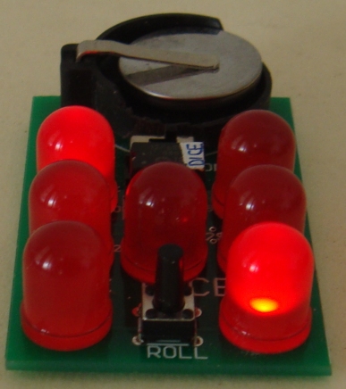
When
the circuit is switched on, the tactile switch is
pressed and the LEDs flash to represent the rolling of
the dice.
The “rolling” gradually slows and a result appears on
the LEDs. After 6 seconds the LEDs go out and the switch
can be pressed again for another “roll.”
Here is the PIC DICE on Printed
Circuit Board:

The negative of the cell
holder goes to the bottom rail
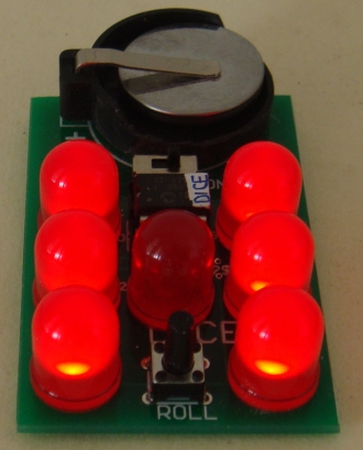
PIC LED Dice now comes with 10mm
Jumbo RED LEDs for $2.50 extra.
Ask for them when ordering.
The PC board is also larger.
|
PIC
Dice
PARTS LIST
Kit: $8.50
plus $4.00 postage |
|
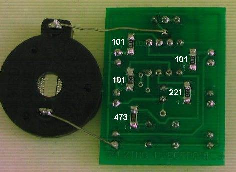
|
3
- 100R surface mount
1 - 220R SM
1 - 47k SM
7 - 3mm high-bright red LEDs
1 - 8 pin IC socket
1 - PIC12F629 microcontroller with
DICE
1 - tactile switch
1 - mini on-off slide switch
1 - coin cell holder
1 - 3v lithium coin cell CR2025
Fine tinned copper wire - 6cm
Fine solder – 20cm
1 - PIC DICE PC Board |
|
|
|
|
LOGIC PROBEE
with
PULSER
(slimline)
Through-hole version
|
|
Kits
are available for this
project from Talking Electronics
$8.80 for through-hole version
|
We have 2 versions of this project. Version 1 uses one-eighth watt
through-hole resistors and version 2 uses surface-mount components.
You can decide which version you want to build and either one will be an
experience.
And the boards now have a mechanical buzzer that produces a much-louder
output.
These are all improvements and reflect the availability of components.
The project works the same as before. But the piezo diaphragms are
hard to get and very expensive.
A LOGIC PROBE is just one piece of equipment to help with
designing/testing and diagnosing a project.
And for $9.00 or $8.80 you can't pass it up.
It has two features above other Logic Probes. A pulser
to produce a waveform that can be injected into a circuit to produce
"clocking" or into audio circuits to determine the relative
amplification of a stage. And a mechanical buzzer to hear the presence of waveforms.
You won't be able to listen to very high frequency signals but many signals in a project
consist of scanning data and these can be detected as audio.
This project forms part of our overall aim to get you into designing
circuits using a microcontroller.
It teaches you how to use a Probe and Pulser and adds to your
understanding and analysis of circuits.
You don't need a Logic Probe until a project DOES NOT WORK.
That's when you reach for it.
And it is based on a very simple circuit.
It provides all the features you need and will detect HIGH/LOW voltages
on 3v to 15v circuits because the power for the Probe comes from the
leads clipped to the power rails of the circuit you are
testing.
This provides automatic adjustment for HIGH and LOW values to equate to
approx 50% of rail-voltage.
The project also has a Pulse LED to show when a single pulse is
detected. This is actually a "pulse extender" and is handy for
the time when you are waiting for a single pulse to arrive to activate a
circuit.
The piezo also monitors the input and you can hear the activity on the
line and compare one line with another.
The PULSER mode delivers a low frequency waveform and this will override
some of the waveforms in a circuit to slow-down the activation of a
circuit to see what is happening.
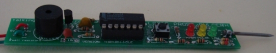
The latest PCB's use a mechanical buzzer (it contains a transistor and
metal diaphragm and
must be connected to the board around the correct way). It is
shown in the circuit above and the images below. It is driven in a very
clever
way by a transistor that is AC coupled to the input-line (from the
probe). It takes 1k to
discharge the 100n quickly so the transistor reacts to the signal.
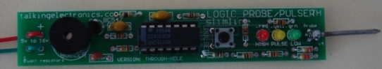
This is the Logic Probe using one-eighth watt resistors.
It is available as a kit for $8.80. (the cheapest Logic Probe kit on
the market)
This project has already been used to solve the following
problems:
No display on the Super Probe MkII project.
The clock pin was injected with the pulser and the Super Probe
MkII showed segments on the display at a very low clock-rate
to prove the microcontroller was working The problem was one of the 20Mhz crystal leads connected to 0v.
The 8x8 Module did not produce a display. The data and clock lines
were probed and it was found the data line was not connected.
The Logic Probe also helped with the input of the Point
Controller project to show when the photo transistor changed
from LOW to HIGH.
The Logic Probe helped to solve a problem with the Hourglass
Timer project. A track was missing !
You don't realise how many times you use a Logic Probe
until you keep a list of the incidents.
The illumination of the LEDs on the Logic Probe tell you a lot
of things. They show if a line is predominantly HIGH or LOW and
the piezo will let you hear the activity on a low-frequency
line. This has helped with the display section of the Stroop
and NIM projects.
It won't solve all your problems, but it will quickly find open
tracks (traces) and let you see the signal on each side of
components, such as LEDs, that are not connected to the 0v rail
(in a multiplexing or Charlieplexing arrangement).
|
Logic Probe
with
Pulser
Slimline
Parts List
for through-hole version
Cost:
au$8.80
plus postage
Kits
are available |
|
5
- 1k resistors
1 - 15k resistor
2 - 220k resistors
3 - 1M resistors
1 - 10n SM capacitor
2 - 100n SM capacitor
1 - 3mm red LED
1 - 3mm yellow LED
1 - 3mm green LED
1 - 14 pin IC socket
1 - CD4069UB
1 - BC547 transistor
1 - mechanical buzzer
1 - tactile switch
1 - 20mm x 1.2mm nail for
probe
20cm red and black hook-up flex
1 - red alligator clip
1 - black alligator clip
20cm very fine solder
1 - Logic Probe/Pulser PC board
- TH |
|
WHY TWO VERSIONS?
We mentioned to a sales outlet that we had a new
Logic Probe kit and said it used surface-mount components. He
wanted a through-hole version for beginners.
So we have two versions.
The PC board is very small so we had to use very small
resistors. The project goes together very easily and if you want
to advance to soldering surface-mount, this is the ideal time to
start.
You just need a pair of tweezers and a fine tipped soldering iron.
Once you try surface-mount you will be hooked. They are faster
to fit and make a much neater result.
USING THE LOGIC PROBE
Connect the red and black alligator clips to the project you are
testing.
This will automatically allow the Logic Probe to recognise a
HIGH and LOW and a change between these two values.
It is the voltage-level at which the Logic Probe changes from
HIGH to LOW or LOW to HIGH that is very important.
It must be very close to 50% of rail voltage.
Suppose you connect the Logic Probe to a 12v supply and work on
a 5v microcontroller project.
When the Probe detects a 5v signal, this will only be 5/12 = 40%
of the input voltage for the IC on the Probe and it will detect
this as a LOW !
That's why the Probe is always connected to the project being
tested.
Use the probe on lots of working projects to see how the LEDs
illuminate and the piezo responds to the signals.
This is the only way to find out what to expect.
You must compare your observations with a circuit diagram as
this will be your "library of resources" for future diagnosis.
When you are working on a faulty project, you will see the red
and orange LEDs brightly lit and the green LED very dull. This
indicates the line is mainly HIGH.
If the frequency of the pulses are between 50Hz and 10kHz, you
will hear them in the piezo.
USING THE PULSER
The project produces an output waveform of approx 330Hz when the
button is pressed.
This can be injected into a circuit to produce lots of different
effects.
The waveform is called a PULSER, CLOCK, INJECTOR, OSCILLATOR or
SIGNAL INJECTOR, depending on the type of circuit being
analysed (and how you want to call it).
It is especially handy when trouble-shooting audio circuits to
detect the gain through a stage. Audio stages are very difficult
to trouble-shoot, especially when three or more sections are DC
coupled. A signal injector will let you know
if a signal is getting through as some sections are current
amplifiers and the amplitude of the waveform does not increase.
CONSTRUCTION
All the parts fit on a slim-line PC board with
surface-mount components used to reduce the size and make to the
project appear very simple.
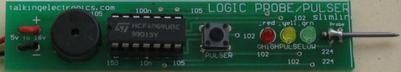
The latest PCB's use a mechanical buzzer as shown on the two
photo's using through-hole components. The piezo diaphragms
became unavailable.
Two more SM parts are on the new PCB to drive the mechanical
buzzer.
(They are not shown in this version of the PC board)
All the values of the surface-mount components are identified on
the top (silk-screen) and the 10n is the same size as the 100n
so don't get them mixed-up.
|
Logic Probe
with
Pulser
Slimline
Parts List
surface-mount version
Cost:
au$9.00
plus postage
Kits
are available |
|
5
- 1k (102) SM
resistors
1 - 15k (153) SM
resistor
2 - 220k (224) SM resistors
3 - 1M (105) SM resistors
1 - 10n SM capacitor
2 - 100n SM capacitor
1 - 3mm red LED
1 - 3mm yellow LED
1 - 3mm green LED
1 - 14 pin IC socket
1 - CD4069UB
1 - BC547 transistor
1 - mechanical buzzer
1 - tactile switch
1 - 20mm x 1.2mm nail for
probe
20cm red and black hook-up flex
1 - red alligator clip
1 - black alligator clip
20cm very fine solder
1 - Logic Probe/Pulser PC board
- SM |
|
|
|
This is another piece of test
equipment from Talking Electronics.
It tests Infra-red LEDs. |
A piece of TEST EQUIPMENT is a useless piece of junk that
hangs around the workbench until it is absolutely needed.
And that's why this project was produced. It lets you know the
intensity of an IR LED and the quality of response when it is
transmitting 38kHz data. Without this project you are
completely frustrated. IR LEDs don't produce any visible
illumination and you need some sort of detector to prove it is
working.
Most cameras can detect Infra-red LEDs but this project also
detects LEDs that are pulsing at 48kHz.
This is the frequency used by infra-red remote controls for TV's
and stereos etc, but there are other very close frequencies and
this detector only responds to 48kHz.
And when you have a LED pulsing at 48kHz, you need to know the
frequency is accurate. The IR LED receiver (on the end of the PC
board) is designed to detect exactly a 48kHz modulation and this
allows you to prove the transmitting IR LED is working
correctly.
THE CIRCUIT:
HOW THE
CIRCUIT WORKS
The circuit is very simple. It consists two different sections
(2 separate circuits). A transistor and IR detector detects
constant IR wavelengths and a 38kHz receiver detects 38kHz IR
signals.
We call the IR receiver a MODULE as it contains many
transistors, resistors and capacitors to produce a number of
amplifying stages that only allows a 48kHz frequency to pass.
This frequency is then compared to an internally generated 48kHz
signal and when the two are identical, the output goes LOW and
the LED connected to the output is illuminated.
The following is a block diagram of the stages. The BPF is a
Band Pass Filter and this stage only allows a very narrow range
of frequencies to emerge on the output of the block. This makes
it easier for the next stages to work and
produce a result.
But these's one little secret that no-one has mentioned.
The 48kHz signal from an IR transmitter must be turned ON and
OFF as a constant 48kHz will not keep the output active !!!!
V4838 Vs VS1838
There are a number of manufacturers of the 38kHz
receivers and some have no markings on them.
The Vishay V4838 is more expensive than the VS1838 but it does
not produce false triggering in sunlight. That's why we have
used it. You need to be careful when buying this component
because some are not marked.
CONSTRUCTION
All the components are fitted to the board and soldered
in the normal way except two items.
The 2k2 surface mount resistor is mounted under the board as shown
in the image above.
The IR receiving transistor is turned 90° after soldering, as
explained below.
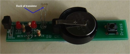
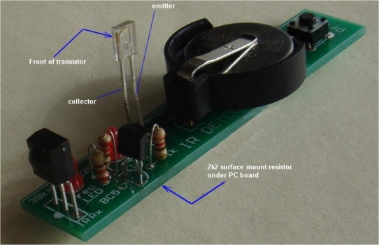
The IR receiver
transistor is bent 90 degrees by holding the two leads
with pliers
and twisting the moving the leads without them affecting
the component. Do not bend them without pliers or the
leads
will break off the plastic case.
The leads are very stiff.
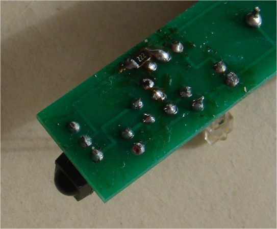
The 2k2 surface-mount resistor is soldered to the lands near the
edge of the board
This is a close-up of the IR transistor
and the 220R on the PC board
The next batch of PCB's will have 2 improvements:
The holes for the IR transistor will be turned 90°
The 2k2 will be on top of the board.
|
|
3 -
220R all 0.25watt
1 - 2k2 surface mount (fitted under board)
1 - IR receiving transistor (any type number)
1 - 38kHz receiving module V4838
2 - 3mm red LEDs
1 - BC547 transistor
1 - push button (tactile switch)
1 - 3v lithium coin cell CR2032
1 - coin cell holder
1 - 20cm fine solder
1 - IR Detector
PCB |
|
|
|
Mains
Tracer
with long probe
Mains Tracer kit is available from
Talking Electronics for $10.00 plus $4.50 postage.
Click
HERE to buy kit. |
This project is one of the
projects that has been designed to support our article:
Become An
Electrician. It's a guide for those who want to become an
Electrician.
Having tried many of the Mains Detectors on the market, to find
they are not sensitive enough, this project was designed with a
number of improvements. The output is a buzzer, rather than a
LED to give a very good indication of the level of
electromagnetic radiation. The buzzer has an internal coil and
transistor, to produce a self-contained oscillator. It just
needs DC to activate. It is not a piezo diaphragm and has NO
piezo element inside the case. It is a metal diaphragm.
A MAINS TRACER is essential when trying to find a cable.
It works on cables in ceilings and walls. It will chirp when the
light-switch is turned-on and pick up the AC in a power cable.
When the probe is near electromagnetic radiation, the buzzer
reacts and this allows you to accurately detect the location of
the cable.
You can also detect the enormous amount of activity around a
computer (mainly the keyboard) and this may account for the
common occurrence of headaches.
You can also check for activity around the head of a bed to see
if electrical wiring in the wall is influencing your
night-sleep.
It will detect signals up to 30cm and is the most sensitive
detector of all those tested.
CONSTRUCTION
All the parts fit neatly on the PC board.
The IC fits into a socket with the cut-out shown on the overlay.
The placement of the transistor is also shown.
The buzzer must be connected with the positive on the buzzer going
to the hole with the "+" sign. The diode must be fitted with the
line on the body down the correct hole and the LED has a shorter
lead (cathode) down the hole marked with the arrow-head on the
symbol.
The most crucial item to connect is the battery snap. The "cup" on a
9v battery is the negative, but we are making a RECEIVING snap, and
the "cup" is the positive. You must look at the diagram to see how
this is connected.
MODIFICATION
200Meg resistors are not very
common and it is necessary to make a value as close as possible to
this value by using a number of 10 Meg surface mount resistors.
Here is the way to place 17 x 10Meg surface mount resistors on
the board:
The land on the top of the board in
the position shown in the diagram above must be totally removed and
any traces of the plate-through hole material must also be removed
from the top surface so the surface-mount resistors do not contact
the 0v rail at this location.
Start at one end of the board and place a resistor. "Butt-joint" the
next resistor to it so that as many resistors as possible can be
placed along the board. We are aiming for 200Meg or as near as
possible.
The value of this resistor is very important as the input impedance
of the chip is very high and anything less than 100M will load the
input and reduce the sensitivity of the probe.
The 470R resistor for the LED can be increased to 1k as we are
supplying a high brightness LED in the kit.
MODIFICATION-2
VERY HIGH
SENSITIVITY
The completed project with the mods to make it
VERY SENSITIVE
The sensitivity of the project can be
increased by putting a "set" on the input voltage so the probe
responds to a smaller waveform.
This is done by adding a 10M resistor into the resistor on the front
end to provide about half-rail-voltage to the input.
This will mean the input only has to rise and fall a few volts to
change the state of the gate.
The "set" does not turn the buzzer on, but when the probe is placed
in an area of electromagnetic interference, only a small amplitude
signal is needed to alter the tone from the buzzer.
The probe will detect interference from the keyboard of a lap top at
20 cm and household wiring at more than 30cm.
You can check the radiation from the screen of your TV and from the
"Smart Meter."
MAINS TRACER -
CIRCUIT-2
The following circuit shows how to produce a high input
impedance using a transistor in emitter-follower mode.
It produces the same high impedance as the circuit above, without
having to use the string of 10M resistors.
The only problem is the circuit is not biased to create the
super-sensitivity of the circuit above.
You have a choice of building either circuit.
The Mains Tracer MkII PC board:
MAINS TRACER
MkII
Both PC boards are
included in the kit with all the components. You can decide which
board you wish to populate.
|
MAINS TRACER
PARTS LIST
$10.00 plus $4.50
postage.
Click HERE
to buy kit |
1 - 470R
1 - 1k for LED in place of 470R on PCB
1 - 1M
1 - 3M3
20 - 10M surface mount resistors
1 - 1N 4148 diode
1 - 3mm red LED
1 - battery snap
1 - CD 4069UB IC
1 - 14 pin IC socket
2 - BC 547 transistors
1 - buzzer
1 - mini slide switch
1 - 20cm fine solder
1 - 10cm tinned copper wire for battery snap
1 - 20cm 0.61 enamelled wire for probe
1 - Mains Tracer PC Board
MkI and MkII
(both boards supplied)
Not in kit: 1 - 9v battery
|
|
|
Point
Controller
using
555 IC |
|
Home
Cost:
$15.00(incl
servo)
plus $6.50 postage
Kits are
available
It is
now $15.00
|
| This projects converts a
manual point into a remotely-controlled point using a servo.
The switch in the kit controls the action and the servo in
the kit does the work. |
This project allows you to manually operate a point via a toggle
switch.
Our project uses a SERVO, for the activation of the point and these
have an output shaft that rotates nearly 300 degrees. But our
project limits the rotation to about 90 degrees and this is enough
to move the rails at the point via a rod called a "linkage."
An "arm" is fitted to the output of the servo to get linear motion
via a short push-rod (from the arm to the rails).
The kit comes with the servo, switch and linkage to create a
remotely controlled point at less cost than any other way.
LINKAGE
You need to connect the servo to the point with a stiff length of
wire called a LINKAGE (also called a PUSH-ROD).
This allows the servo to produce LINEAR MOTION and the project
reduces this linear motion to a very short distance to suit the
"THROW" of the point. This is done by reducing the rotational
movement of the servo via the circuit and using a hole close to the
axel to produce just the right amount of "throw."
This is the distance the point must be moved to change the rail(s)
from one position to the other.
Connection between the point and the servo is done with a short
length of copper or steel wire included in the kit.
It needs to be bent so it can be connected to the servo and fitted
into the hole in the lever on the track.
You need to work out where to position the servo and then it can be
housed in a PECO Platelayer hut.
The servo is laid on its side to take up the least room and held in
position with double-sided tape.
When the servo has proven to be working correctly, it is glued to
the baseboard with acetone cement around the edge of the servo.
|
THE CIRCUIT
The circuit is quite unconventional and it's the
first time you will see such an usual design.
That's because we design unusual things.
The circuit delivers two different "timing values" to the 555 to
produce clockwise and anticlockwise rotation. These values
produce about 90° rotation and this is all you need to get the
"throw" required.
The LEDs illuminate to show the direction of the point.
The project also includes a 2 metre extension lead so the servo
can be located 2 metres from your control panel.
The project will work from a wide range of voltages, including
AC or DC and as the voltage increases over 10v, the only effect
will be the BC338 will get slightly warm if the point is
constantly changed. The transistor will pass 800mA so it is
easily capable of delivering the 250mA for the servo.
The single diode on the power supply produces half-wave
rectification and although this does not produce very smooth DC,
none of the circuit is very sensitive to noise. The first 100u
provides a small amount of smoothing and the BC338 improves this
enormously by only using the voltage from 0v to 6v2 and the
ripple will be above this voltage. This is done by using a 6v2
zener on the base. The output is improved further by the second
100u to give the smooth voltage we need.
The 47k and 120k produce the timing (the HIGH) for the 555 to
move the arm on the servo about 90°.
Either the 47k or the 120k is taken to the 5v6 rail via a PNP
transistor and is turned ON to feed the 22n on the 555.
When the switch is changed to the other position, the other
transistor operates the servo via the 555 in the other
direction.
THE KIT
The kit is cheaper than buying all the parts separately from
local stockists and the LEDs are high bright because the current
is only about 1 milliamp. The 90° header for the servo allows
the 3-pin plug to be close to the board. There are a few
components in the kit that are not readily available separately
and that's why a kit is the best option.
ASSEMBLY
All the components fit on the board and the LEDs show the
position of the point.
The toggle switch can be fitted to the board or mounted on your
control panel.
The kit comes with a 2 metre extension lead (components) so the
board can be positioned near the operator and the servo plugged
into the 3-pin connector on the extension lead.
|
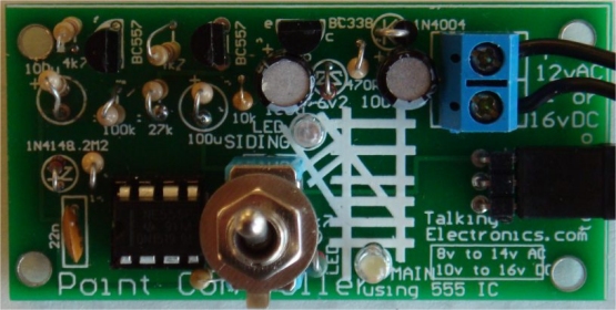
Close-up of the components
on the PC board. Ver2 of the board has updated markings.
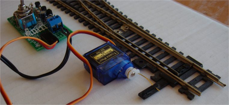
The output of the servo has the arm cut short so only one hole is
available for the thick copper wire.
Bend the wire around the arm and use a hot soldering iron to melt it
into the arm.
Keep the wire long so it provides a force to keep the moveable rail
pressed against the outer track
in each direction.
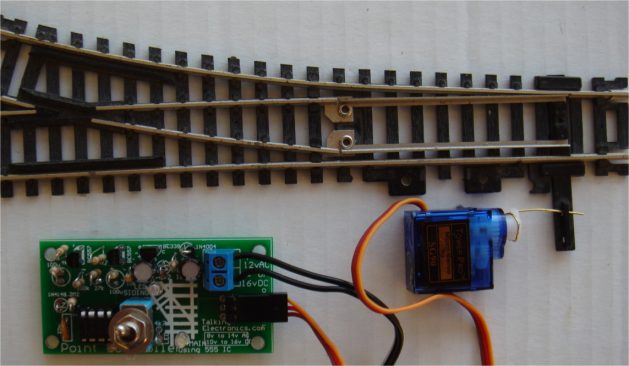
The kit comes with 2 metre extension lead components for the servo.
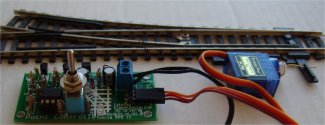
|
The super-bright LEDs are very bright and show the position of
the point:
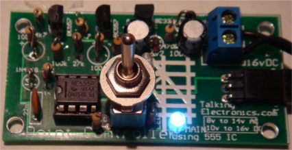
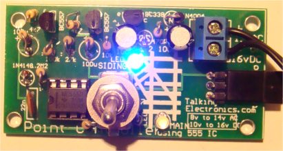
THE POWER
SUPPLY
This project
needs a supply of about 12v AC or DC and a current of about
200mA.
This means a small power supply can be used and some are rated
at 200mA and 500mA.
The voltage needs to be higher than 8v and you can use two 5v
adapters to make a 10v supply, as shown in the following
diagram:
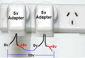
A Plug Pack, Wall Wort or Adapter is the best as it is
completely sealed and the output is insulated and isolated from
the mains.
These are cheaper than making your own power supply and you can
use some of your (discarded) 5v supplies from your old-model
phones. Make sure the wiring is connected so the voltages are
ADDED to the output. Even 300mA, 500mA and 1 amp adapters can be
connected as we are only requiring 200mA.
You can do the same with AC adapters and although the output is
changing many times a second, the output leads have to be
connected so they ADD to the output. Connecting them the wrong
way with produce ZERO output.
You can connect adapters of different voltages and current and
even AC and DC adapters as the circuit will accept all these
variations. You can connect an AC adapter either way around to a
DC adapter and it will produce AC of the combined voltage for
the first half-cycle and zero voltage for the second half-cycle.
This is a good project to use-up those discarded adapters.
BEFORE YOU
START !!
Before you start thinking about buying the
kit for this project, look at the range of POINT CONTROLLER
projects from Talking Electronics and make sure this is the one
you need.
The "point" needs to be a manually operated point. This projects
does all the conversion.
It operates a single point and converts it to a
remotely-operated point. It is the cheapest conversion you can
get and uses a servo to do the work.
You can use AC or DC from about 10v to 14v (16v DC) and you can
hide the servo in a hut or shed. The LEDs on the PC board show
the condition of the track and the kit comes with a 2 metre
extension lead. You just need a little bit of expertise to fit
the wire between the arm (on the servo) and the lever on the
track that changes the position of the point. The photos will
help you do this.
|
Point Controller
using 555 IC
Parts List
Cost:$15.00(incl servo) plus
$6.50 postage
Kits are available
(Pre-assembled kits $5.00 extra) |
|
1 -
470R all 0.25watt
1 - 2k2
2 - 4k7
4 - 10k
1 - 47k
1 - 120k
1 - 2M2
1 - 22n ceramic
2 - 100u electrolytic
1 - 6v2 zener
1 - 1N4148 diode
1 - 1N4004 diode
1 - 3mm green LED (high bright)
1 - 3mm white LED (high bright)
1 - BC338 transistor
2 - BC557 transistors
1 - 555 IC
1 - 8 pin IC socket
2m - 3-core flat ribbon for servo extn lead
1 - 2-screw terminal block for power-in
1 - 3-pin 90° header for servo
1 - 3-pin male for servo extension lead
1 - 3-pin female socket for servo extension
1 - 20cm very fine solder
1 - Servo with arms
1 - Double-sided tape to temp hold servo
(glue needed to hold the servo in place)
1 - 10cm length thick copper wire for linkage
1 - toggle switch SPDT
1 - Point Controller
using 555 IC PCB
|
|
|
|
Gripper kit is available from
Talking Electronics for $10.00 plus $6.50 postage.
You will also need a servo and extn lead $5.50
and the parts to make the GRIPPER $3.00
Click HERE
for details.

The GRIPPER in this project is constructed
from green laminate and requires a lot of care and skill to shape the components
using a hack-saw, file, sandpaper, pliers and cutters.
Some of the components will come partially cut-out and the rectangle cut-out has
been predrilled with fine holes so you can snip the inside and it will break
away from the surroundings. Do no "punch-out" the rectangle as the laminate will
break around the outside.
The two arms need special care and each unwanted part must be carefully broken
away in small pieces, otherwise the arm will break.
Once you have removed the unwanted bits and cut along the outside with a
hack-saw, the curved inside sections of the arms can be filed with a round or half-round file until
the through-hole plating is removed.
The curved edges and corners are smoothed with sandpaper by rubbing the arm on a sheet of
sandpaper on a table.
All the other edges are smoothed in the same way until all the components look
like those in the photo. This will take over 1 hour.
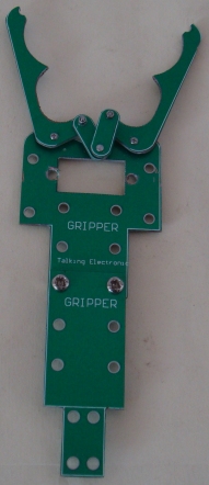
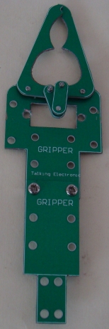
A set of nuts and bolts come with the arm and a sheet of instructions comes with
the kit.
|
PARTS LIST
$3.00 plus postage.
Click
HERE for details |
Parts for gripper:
6 Green parts that have to cut and shaped using
files, sandpaper, pliers and cutters.
Set of nuts and bolts and screws
|
ooooooooooooooooooooo00000000000000000000000oooooooooooooooooooooo
The GRIPPER needs a SERVO and a CONTROL
MODULE.
The Control Module is called SERVO TESTER and it also has other
names.
|
Servo Tester
Kits are available from
Talking Electronics for $10.00 plus $6.50 postage.
You will also need a servo and extn lead $5.50
Click
HERE to buy kit.
|
This project has 5 different names and 5
different uses.
It is also know as, and is used in these projects:
REMOTE BOOM GATES
GRIPPER
SERVO TESTER
CONTINUOUS ROTATION SERVO TESTER
POINT CONTROLLER using SERVO
(these projects are on
TalkingElectronics.com website)
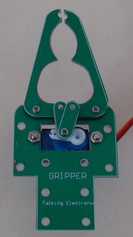
Servo fitted to Gripper
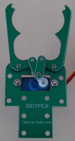
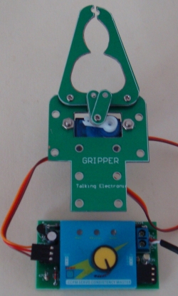
Control Module connected to Servo
Turn the knob to open and close the Gripper
The SERVO TESTER project connects a knob on a
potentiometer to a servo so you can open and close the Gripper as fast
as you turn the knob.
CCPM SERVO MODULE
The heart of the project is a SERVO CONTROL MODULE.
It is fitted to the Printed Circuit Board with stand-offs (connectors).
The images below show the CCPM SERVO MODULE.
The printed circuit board is actually a power supply to deliver 5v5 to the module
from an AC or DC voltage from 9v AC or DC, but not higher than 12v AC or DC as
the regulator transistor will get too hot.
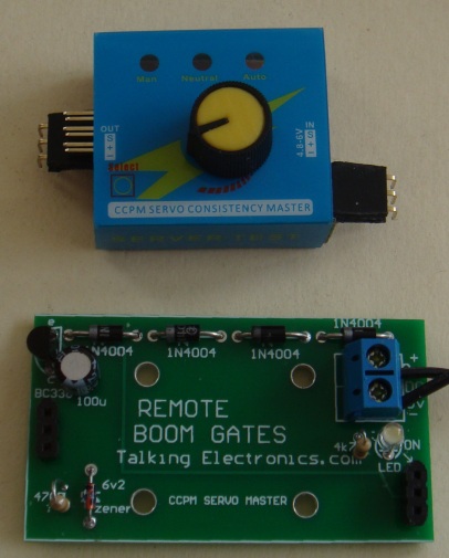
The 90° connectors fitted to the CCPM
Module
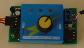
The CCPM Module fitted to the PC
board
THE CIRCUIT
The heart of the project is SERVO TESTER MODULE. It
produces a set of pulses that vary in width and these are detected by the
electronics inside the servo to activate the motor. The motor turns and output
shaft that is connected to a variable resistor (potentiometer) and then the
signal from the pot is equal to the signal being received from the SERVO TESTER
MODULE, the motor stops.
The module needs a 5v supply and this has been done with components on the green
Printed Circuit Board. We have used a transistor and 5v6 zener to produce a 5v
regulated supply.
You can use a voltage from 8v to 14v DC or 6v to 12v AC and the circuit will
deliver 5v DC to the module. It has been tested with 12vAC and the transistor
gets hot, so just operate the servos for short periods.
The white LED on the board indicates the supply voltage is present.
The circuit has been drawn to follow the
components on the board to make it easy to see what the components do.
The 4 diodes are a bridge to allow either AC or DC and it does
not matter which way the power leads are connected.
Measuring the 12v supply, the circuit takes 30mA when "sitting around" and up to
100mA when the servo is operating.
EXTENSION LEAD
The kit contains components to make an extension leads, so the control knob can
be about a metre from the Gripper. The lead is a 3-wire ribbon cable
and the ends are soldered to 3-pin male and female connectors. Make sure
you mark the data wire with white paint on each of the plugs and sockets so the
leads are connected correctly.
CONSTRUCTION
All the parts fit neatly on the PC board.
The transistor, diodes, electrolytic and LED are identified on the board
and must be fitted correctly.
The screw terminals on the 2-connector block are for the power supply
leads.
HOW IT WORKS
Once everything is connected, the control knob on the CCPM
Module will turn the arm on the servo clockwise or anticlockwise at the
same speed as you turn the knob.
The module has a SELECT button that activates the servo automatically
and moves the output fully in one direction and then the other and
constantly repeats. Pushing the button again makes the servo go to
centre position and stays there.
|
PARTS LIST
Kits are available from
Talking Electronics for $10.00 plus $6.50 postage.
You will also need a servo and extn lead $5.50
Click HERE
to buy kit |
1 - 470R
1 - 4k7
1 - 100u 25v electrolytic
4 - 1N 4004 power diodes
1 - BC338 transistor
1 - 3mm white LED (high bright)
1 - 6v2 zener
2 - 3pin male headers 90°
2 - 3pin male headers
4 - 3pin female headers
1 - CCPM Servo Control Module with pot
1 - 2-screw connector block
1 - 20cm fine solder
1 - REMOTE BOOM GATES PC Board
for extension lead:
1m 3core flat cable
1 - 3pin male header
1 - 3pin female header
|
|
Email me with any changes or
improvements or additions you would like to be included:
Colin Mitchell
These projects are also on Talking Electronics.com website and will
contain more information.
1-11-2017
|