|
RGB |
|
|
This project
produces a number of effects on an RGB LED.
You can also
produce your own sequence (by using the 3 buttons) and store it as
sequence 1.
You can build the project on Matrix Board or buy a complete kit with
pre-programmed chip.
You can also program the chip yourself and use this project as the
beginning to: "learning to write your own programs."
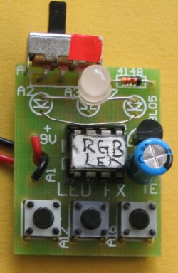
RGB
LED FX on PCB
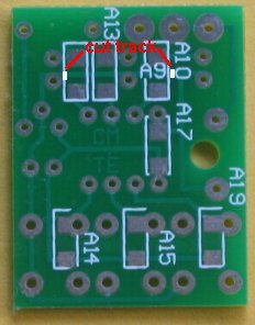
Note the link
below the RGB LED
The CIRCUIT
The project creates a number of effects on an RGB LED,
including PWM (Pulse Width Modulation) to show the effect of turning on
the LED(s) for a very short period of time then turn the LED(s) off for
a longer period of time. THE RGB LED SURFACE-MOUNT COMPONENTS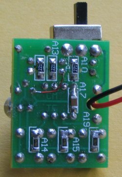
Underside of LED
FX showing SM
components
The PC track is cut just before the 221 SM resistor
and just after the 271 SM resistor (see note below).
Note the link using enamelled wire.
The 47k SM resistors are not needed as the
micro has 47k internal pull-up resistors enabled.
RGB
LED FX Circuit
The circuit is very simple. It is
just an RGB LED and 3 switches. All the work is done by the micro.
We have added a 5v regulator and diode so the project can be connected
to all sorts of voltages and the regulator will not be damaged if the
supply is connected the wrong way around, as the diode will simply not
conduct. .
It will work on 6v if the regulator is removed or on 7v to 15v (AC or
DC) with the regulator fitted.
This makes it suitable for a 9v battery or the AC supply from a model
railroad. I know you are going to say "it is inefficient using a 9v
battery" but it is convenient. In fact you can use a set of very
old cells, providing they produce at least 8v and this is a good project
for using old cells.
This will reduce the brightness and also consume less current. When this
is done to all three LEDs a range of colours can be created. This
involves delivering a different percentage of ON-TIME for each LED to
produce a specific colour.
The major purpose for the introduction of the RGB LED was to produce a
wide range of colours, plus white.
This allows it to be used for screens such as TV screens, to reproduce
moving images.
Any sort of display requires a lot of LEDs and this requires many
drive-lines. A single 8-pin micro an only drive one or two LEDs and we
have opted to use a single LED and show the range of effects that can be
produced.
The RGB LED supplied in the kit is high-bright. It is
too bright to look at directly but can be used for all sorts of
applications and effects. You can reduce the brightness by increasing
the value of the current-limiting resistors to suit your own
application. The PWM sequences reduce the brightness and you can observe
how effective they are at reducing the current consumption. We have used
220R and 270R resistors to reduce the brightness so the output is
not too bright.
They also make the project look simpler as they "disappear" under the
board; or if you are developing a single-sided project, they reduce the
size of the final design.
You will need fine tweezers to hold
them in place while one end is soldered.
Always use very fine solder as you only need very little for each
component and the main reason for adding extra solder is to take advantage of
the flux to clean the connection. Always solder resistors with the value
showing.
So, we have two areas of interest. Construction and programming and
it's up to you to take it on.
The project is designed for all sorts of uses, including models such as
train layouts, alarms and similar effects.
But the real thing we want to get across, is programming.
This is another example of using a simple 8 pin chip to provide a number
of features that would take many logic chips (such as counters and gates) and lots of components to
duplicate.
It also highlights our method of hand-coding as an effective way to
produce a program.
This project uses about 400 instructions to produce the effects and it uses the EEPROM to store the sequence
produced by the user (sequence 1) - and show it at turn-on.
In this respect, some of the sub-routines in the program are quite complex and suitable
for the advanced programmer. However, if you are a beginner, you can
read through the program and most of the sub-routines will be easy to
follow as each line of code is explained. You have to start somewhere
and this project offers a challenge.
Most projects with a program of this complexity are only available as a
pre-programmed chip or only the hex code is available. There is usually no
attempt at educating the reader in programming.
That's the difference between our projects and all others.
We offer a learning curve.
For every hour of effort you put into reading, building and using one of
our microcontroller projects, you get the experience of 100 hours of
effort that has been put into the design to make it appear simple.
All you have to do is start . . .
|
INSTRUCTIONS FOR USE There are 25 sequences. The first sequence can be created by the user. It currently produces a very slow flash-rate as it has not be programmed. The other 24 sequences are pre-programmed. Turn project ON then push the first button (called SwA) and hold it down and the sequence will change to the next sequence. Release the button and allow the sequence to cycle. Push SwA again and the sequence will change. You need to allow each sequence to cycle with the button not-pressed and then push SwA and keep it pressed until a new sequence shows. This is due to the debouncing in the program. See below for the list of 25 sequences. TO CREATE YOU OWN SEQUENCE. 1. Press SwA and at the same time, turn project ON. 2. Release SwA and press the switches in any order (up to 15 steps). A step or delay cannot be longer than 2 seconds as the program will "time out." When finished, wait 3 seconds and the sequence will show on the LEDs. 3. Turn project off and on. The new sequence will appear as the first sequence. TO MAKE ANY SEQUENCE THE FIRST SEQUENCE Any of the sequences can be saved as the first sequence, as follows: 1. Turn the project ON and increment the sequences. 2. To save the desired sequence, press SwB. The display will die. 3. Turn project OFF then ON. The desired sequence will show at start-up. 4. To delete this feature, push SwC and at the same time, turn project ON. |
THE
SEQUENCES
There are 25
pre-programmed sequences. Here is the list:
|
Sequence 1:
This sequence is created by you.
See above for details on creating your own
sequence. Sequence 1A: Most of the colours from an RGB LED Sequence 2: red LED @ 50% PWM Sequence 3: green LED @ 50% PWM Sequence 4: blue LED @ 50% PWM Sequence 5: white @ 50% PWM Sequence 6: red LED @ 20% PWM Sequence 7: green LED @ 20% PWM Sequence 8: blue LED @ 20% PWM Sequence 9: white @ 20% PWM Sequence 10: slow red, green, blue change @ 100% PWM Sequence 11: slow red, green, blue change @ 50% PWM Sequence 12: slow red, green, blue change @ 20% PWM Sequence 13: red, blue, red, blue Sequence 14: red on red off Sequence 15: green on green off Sequence 16: blue on blue off Sequence 17: white on white off Sequence 18: red red red blue blue blue Sequence 19: random white flicker Sequence 20: slow fade up-down red Sequence 21: slow fade up-down green Sequence 22: slow fade up-down blue Sequence 23: slow fade up-down white Sequence 24: fast fade up-down white |
PROGRAMMING THE
CHIP
The kit comes with a pre-programmed PIC chip but if you want to program
your own chip or modify the program, the .hex file is available as well
as the assembly file, so you can see how the program has been written
and view the comments for each line of code.
The PIC12F629 is one of the smallest micros in the range but you will be
surprised how much can be achieved with such a tiny micro.
The program contains sub-routines to produce delays, sequences on the
display and both read and write EEPROM jobs that require accurate code
- including a special sequence - called a handshaking sequence that
prevents the EEPROM being written due to glitches.
Even a program as simple as this is not easy to put together and to
assist in this area, we have provided a whole raft of support material.
Not only do we provide a number of programs with full documentation but
our approach to programming is simple.
It involves a method of "copy and paste" whereby sub-routines
are taken from previously written code and copied into your program. Any modifications are
made in very small steps so that each can be tested before adding more
code.
This is exactly how we produce a complex project. Each step is written
and tested before adding the next step.
This saves a lot of frustration as it is very easy to add a line
of code that is incorrect and get an unsuspected result.
If you follow our suggestions you will buy a programmer ("burner")
called a PICkit-2 if you are using a laptop. It is the cheapest and best on the market
and comes with
a USB
cable and 2 CD's containing the programs needed to "burn" the chip.
If you are using a desk-top and/or tower with a serial port, you can use
a cheaper programmer called MultiChip Programmer from Talking
Electronics. You
will also need NotePad2 to write your .asm program. This can be
downloaded from Talking Electronics website. You will use
RGB LED_FX.asm or
RGB LED_FX-asm.txt as a template for your
program, plus a 6 pin to 5 pin connector that fits between the burner
and the project. This is also available on Talking Electronics website.
As we said before, this project is for medium-to-advanced programmers as
it is very compact and does not have in-circuit programming pins.
To be able to modify the chip you will need a programming socket and
this can be obtained from one of our other projects that contains the 5
pins for in-circuit programming.
You can then put the chip into the other project to be programmed and
modified and re-fit it into this project for execution.
PROGRAMMING LANGUAGE
There are a number of kits, programs and
courses on the market that claim and suggest they teach PIC Programming.
Most of these modules and courses use a PIC microcontroller as the chip carrying out
the processes, but the actual programming is done by a proprietary
language invented by the designer of the course.
Although these courses are wonderful to get you into "Programming
Microcontrollers" they do not use any of the terms or codes that apply
to the PIC microcontroller family.
All our projects use the 33 instructions that come with the PIC
Microcontroller and these are very easy to learn.
We use the full capability of the micro and our pre-programmed chip is
less than the cost of doing it any other way.
In addition, anything designed via our method can be instantly
transferred to a PIC die and mass produced. And we use all the input
pins and all the memory of the chip. The other approaches
use less than 25% of the capability of the memory and one of the pins is not available.
In fact it would be difficult to reproduce this project via any of the opposition
methods. It would require a larger chip and more expense.
You can use our method or the opposition. Just be aware that the two are
not interchangeable.
Ours is classified as the lowest "form" (level) of programming - commonly called
machine code - invented in the early days of microprocessors - and now
called mnemonic programming as each line of code is made up of
letters of a set of words. The opposition uses a higher level language
where one instruction can carry out an operation similar to a
sub-routine.
But you have to learn the "higher level language" in order to create a
program. And this requires a fair amount of skill and capability.
It sounds great and it is a good idea. But if you want to learn PIC
programming, it does not assist you. It is "a step removed" from
learning PIC language. The other disadvantage of the opposition is the
"overhead." The 1,000 spaces allocated for your program is filled with
pre-written sub-routines. You may require only 10 of these sub-routines but ALL
of them are loaded in the memory space. And they take up all the memory.
You have no room for your own program.
To get around this the opposition uses the 128 bytes in EEPROM to deliver
instructions on how to apply the sub-routines. This provides about 30 powerful instructions using their
language called BASIC (or a similar language).
It's a bit like selling a diary filled with all the paragraphs you need
to express yourself, and leaving a few blank pages at the back for you
to write single lines such as: see page 24, paragraph 7, see page 63
paragraph 4, to create your diary entries.
It depends on how much you want to be in charge of writing a program. Using
our method is like writing your own auto-biography. Using the opposition
is like getting a "ghost writer."
When using a higher level language to create a program, you have absolutely no
idea how the code is generated for the micro.
In some of the developmental kits, the code is "locked away" and you are
NEVER able to access it.
Everything runs smoothly until a fault appears. With our method you can
see the code. With the other methods, you cannot see the code - it's
like doing key-hole surgery without the advantage of an
illuminated endoscope to see what you are doing.
Everything has its place and our method of hand-assembly is only
suitable for very small micros and you will eventually need to "learn a
high level language." The PIC12F629 has over 1,000 locations for code
and this equates to more than 20 pages when printed, so this is about
the limit to doing things by hand.
But our drive is to show how much can be done with the simplest devices
on the market, at the lowest cost.
Anyone can show you high-technology at a high price but this is not
where you start and this is not where you get enthusiasm.
We provide the things to get you started. That's the difference.
CONSTRUCTION
The RGB LED FX
project is built on the same PC board as LED FX.
Only two modifications have to be made.
Cut a track in two places as shown in the second photo below and fit a tinned
copper wire link between two holes on the top of the board as shown in
the first photo. The first photo shows how to fit the leads of the RGB LED:
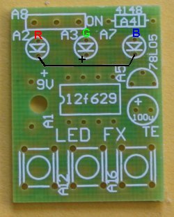
The leads of the RGB LED are bent as shown in the following diagram so it fits down the holes in the PC board:
The kit of components comes with all the parts you need to get the
project working, including a pre-programmed chip and PC
board.
To modify the program you will need a PICkit-2 programmer and this comes
with 2 CD's containing all the software needed for In-Circuit
Programming.
You will also need a lead (comes with PICkit-2) to connect the programmer to your lap top via
the USB port and an adapter we call 6pin to 5 pin
Adapter to connect
the PICkit-2 to your project.
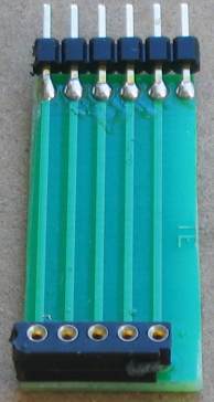
6pin to 5pin
Adapter
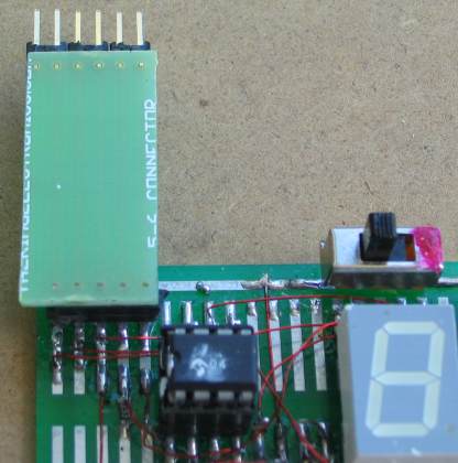
Adapter connected for In-Circuit Programming
(the chip is placed in another project for in-circuit
programming
or any PC board with 5 In-circuit Programming pins)
The
PROGRAM
The program does a bit of
detecting when turned on. It detects to see if a bit has been set in
EEPROM to tell the micro to go to a required sequence or start with
sequence 1.
It also detects if switch A or C has been pressed at the instant the
project is turned on so that the micro is directed to the sub-routine
where the user-sequence can be entered or if the EEPROM bit is to be
cancelled.
All this gets done in the SetUp routine and then the micro goes to Main.
In Main, the program increments a "jump" file and calls a table where it
finds a directive to go to a particular sub-routine.
The sub-routine is executed and the micro goes back to Main where it
looks for a release of SwA. This forms part of a key debounce as the key
must be fully debounced as it is advancing the micro through the
sequences.
To provide a totally reliable debounce, the key is detected as not being
pushed for the duration of a whole cycle of a sequence and a separate loop is then executed where the key can be
detected as being pushed, to advance the program to the next sequence.
To create your own sequence as sequence1, the project is turned off and
SwA pressed while turning the project ON.
This sends the micro to a sub-routine called Attract.
As soon as SwA is released, the program starts to time the duration when
a switch is not pressed and it "times-out" after 2.5 seconds.
The program also times the duration when a LED is illuminated. It also
accepts 2 or 3 LEDs illuminated at the same time. These are all clever
instructions that need to be looked at to see how they operate.
Up to 15 steps can be entered and each step occupies three bytes. The
first value identifies the illuminated LEDs, the second byte identifies
the ON duration (in increments of 5mS) and the third byte identifies the
OFF time.
These 45 bytes are contained in files 30h to 5Fh.
When a switch is not pressed for 2.5 seconds, the program "times out"
and sends the values to the EEPROM. It then shows the sequence on the
LEDs.
If the project is turned off and on again, this sequence will be
displayed as sequence1.
To replace the sequence with something else, simply repeat the steps above.
If you want one of the pre-programmed sequences to appear each time the
project is turned on, simply advance through the sequences by
pressing SwA and when the desired sequence is playing, push SwB.
This will record your choice. Turn the project OFF then ON again and the
chosen sequence will be displayed.
To remove this feature, press SwC when the project is off and at the
same time, turn the
project ON.
All these feature have been added to the program, one at a time, and it
is important to add them in the correct order. For instance, you can only add a removal feature after the
initial feature has been produced. Reading and writing to the EEPROM is
a most complex operation and the instructions must be laid out as shown
in the program, as they include a hand-shaking sequence. When you need this
code it is copied and
pasted in its entirety, to prevent a mistake.
Nearly every instruction has a comment to explain not only what it does, but why it was chosen.
If you think you can start programming without reading programs from
other developers, you are wasting your time.
No individual can work how to do many of the tasks via the simplest set
of instructions and you will find some programmers have used complex
code to do the simplest task.
That's why you have to pick out the "wheat from the chaff" and
remember a good routine, while discarding the over-complex sets of code.
This brings up an important point.
Don't expect to be an A1 programmer in a week. It takes time to absorb
the skills of programming and it is really only understood by a
microscopic percentage of electronics enthusiasts. If you take it up and
understand it, you are one of the microscopic few.
It is a world that, once you are in, will open up a whole new field of
ideas and development.
It's like taking up a new spoken language and, in fact, a program reads
like a book, so the analogy is very close.
There are some very "clever" instructions such as XOR where you can
compare two files by using the XOR function and determine if they are
the same. And very powerful instructions such as djnz that decrements a
file and if it is zero, the micro jumps over the next instruction.
Other clever instructions transfer the contents of a file to another via
the "carry."
You cannot be expected to know these "tricks" unless you
study programming. That's why we are here.
Here are the files you will need:
RGB LED_FX.asm
RGB LED_FX-asm.txt
LED_FX.hex
;RGB LED FX.asm
;****************************************************
;RGB LED FX.asm                                     *
;25 sequences to demonstrate the possibilities for  *
;an RGB LED                                         *
;22-5-2011                                          *
;****************************************************
;
;
;            --+---------------+-------+-------+---------- +5v
;	       |              _|_     _|_     _|_
;              |             R\ /    G\ /    B\ /
;              |Vdd ---v---    |       |       |
;              +---|1   Gnd|  | |     | |     | |
;                  |       |  | |220R | |150R | |150R
;   +--------------|GP5    |   |       |       |
;   |              |    GP0|---+       |       |
;   |     +--------|GP4 GP1|-----------+       |
;   |     |        |       |                   |
;   |     |     +--|GP3 GP2|-------------------+
;   |     |     |  -------
;   o     o     o  PIC12F629
;  A /   B  /  C /
;   /      /    /            common anode RGB LED
;  |      |    |
; -+------+----+---------------------------------------- 0v


	list	p=12F629
	radix	dec
	include	"p12f629.inc"

		errorlevel	-224	; Don't complain about tris
		errorlevel	-302	; Don't complain about BANK 1 Registers


	__CONFIG   _MCLRE_OFF & _CP_OFF
                        & _WDT_OFF & _INTRC_OSC_NOCLKOUT  ;Internal osc.

;     _MCLRE_OFF  - master clear must be off for gp3 to work as input pin

;****************************************************************
; variables - names and files
;****************************************************************


temp1		equ 20h	;
temp2		equ 21h	;
temp3		equ 22h	;
temp4		equ 23h	;
jump		equ 24h	;jump value for table1
fadeUp		equ 25h
fadeDwn		equ 26h
sequences	equ 27h
sw_duration	equ 28h
testing		equ 29h
loops		equ 2Ah ;


;****************************************************************
;Equates
;****************************************************************
status		equ 0x03
rp1		equ 0x06
rp0		equ 0x05
GPIO 		equ 0x05


status		equ 03h
option_reg	equ 81h


		; bits on GPIO

pin7		equ	0	;GP0  red LED = A
pin6	 	equ	1	;GP1  green LED = B
pin5		equ	2	;GP2  blue LED  = C
pin4		equ	3	;GP3  Sw A
pin3		equ	4	;GP4  Sw B
pin2		equ	5	;GP5  Sw C


		;bits

rp0		equ	5	;bit 5 of the status register


;****************************************************************
;Beginning of program
;****************************************************************
	org	0x00
	nop
	nop
	nop
	nop
	nop
SetUp	bsf	status, rp0 	;Bank 1
       	movlw	b'11111000'	;Set TRIS  GP0,1,2 out   GP3,4,5 input
	movwf	TRISIO
	bcf     option_reg,7    ;pull-ups enabled
	bcf	status, rp0	;bank 0
	movlw   07h         	;turn off Comparator ports
        movwf   CMCON       	;must be placed in bank 0
	clrf 	GPIO       	;
	decf    GPIO,1          ;turn off all LEDs in RGB LED
	call	_memory
	btfss	gpio,5		;SwA to: "record new sequence"
	goto	record
	btfsc	gpio,3		;SwC removes attract sequence
	goto	$+.10
	movlw	0FFh
	bsf	status,rp0	;select bank1
	movwf	EEDATA
	bcf	status,rp0	;select bank0
	movlw	.101
	bsf	status,rp0	;select bank1
	movwf	EEADR
	bcf	status,rp0	;select bank0
	call 	write
	movlw	.101
	bsf	status,rp0
	movwf	EEADR
	bsf	EECON1,0   ;starts EEPROM read operation storing result in EEDATA
	movf	EEDATA,w	;move read data into w
	bcf	status,rp0
	xorlw	.8		;look for 8 - for Attract mode
	btfsc	03,2
	goto	Attract_Seq	;selected sequence will appear first
	goto 	Main


;****************************************************************
;* Tables 			*
;****************************************************************

table1	addwf   PCL,F  ;02h,1  add W to program counter
	retlw   .10     ;
	retlw   .50
        retlw   .30     ;
	retlw   .50
	retlw   .100    ;
	retlw   .40	;program starts at bottom of table
	retlw   .10     ;
	retlw   .50
        retlw   .30     ;
	retlw   .50
	retlw   .60     ;
	retlw   .10     ;
	retlw   .50
        retlw   .10     ;
	retlw   .50
	retlw   .100    ;
	retlw   .20     ;
	retlw   .50
        retlw   .30     ;
	retlw   .50
	retlw   .70
	retlw   .60     ;
	retlw   .100    ;
	retlw   .50
        retlw   .100    ;
	retlw   .50
	retlw   .100    ;
	retlw   .70     ;
	retlw   .50
        retlw   .30     ;
	retlw   .50
	retlw   .70     ;

table2	addwf   PCL,F           ;02h,1  add W to program counter

	goto	seq1
        goto	seq1A
	goto	seq2
	goto	seq3
	goto	seq4
	goto	seq5
	goto	seq6
	goto	seq7
	goto	seq8
	goto	seq9
	goto	seq10
	goto	seq11
	goto	seq12
	goto	seq13
	goto	seq14
	goto	seq15
	goto	seq16
	goto	seq17
	goto	seq18
	goto	seq19
	goto	seq20
	goto	seq21
	goto	seq22
	goto	seq23
	goto	seq24


;********************
;* Delays           *
;********************

_xuS	movwf	temp2
_uS	movlw	.10
	movwf	temp1
	decfsz	temp1,f
	goto	$-1
	decfsz 	temp2,f
	goto 	_uS
	retlw 	00

_ZuS	movwf	temp2
	goto	$+2
	goto	$+2
	decfsz 	temp2,f
	goto 	$-3
	retlw 	00


_xmS	movwf	temp2
_x	nop
	decfsz 	temp1,f
	goto 	_x
	decfsz 	temp2,f
	goto 	_x
	retlw 	00

	;1mS delay for PWM

_1mS	movlw	01h
	movwf	temp2
	nop
	decfsz 	temp1,f
	goto 	$-2
	decfsz 	temp2,f
	goto 	$-4
	retlw 	00


	;5mS delay for increments in timing for "New Sequence"

_5mS	movlw	05h
	movwf	temp2
_5	nop
	decfsz 	temp1,f
	goto 	_5
	decfsz 	temp2,f
	goto 	_5
	retlw 	00


_10mS	movlw	0Ah
	movwf	temp2
_10	nop
	decfsz 	temp1,f
	goto 	_10
	decfsz 	temp2,f
	goto 	_10
	retlw 	00


_50mS	movlw	.50
	movwf	temp2
_50	nop
	decfsz 	temp1,f
	goto 	_50
	decfsz 	temp2,f
	goto 	_50
	retlw 	00

_100mS	movlw	.100
	movwf	temp2
_100	nop
	decfsz 	temp1,f
	goto 	_100
	decfsz 	temp2,f
	goto 	_100
	retlw 	00


_150mS	movlw	.150
	movwf	temp2
_150	nop
	decfsz 	temp1,f
	goto 	_150
	decfsz 	temp2,f
	goto 	_150
	retlw 	00

_250mS	nop
	decfsz 	temp1,f
	goto 	$-2
	decfsz 	temp2,f
	goto 	$-4
	retlw 	00


;****************************
;* Sub Routines 	      *
;****************************

_memory
	movlw	.48
	movwf	temp1
	movlw	2Fh
	movwf	fsr
	incf	fsr,f
	movlw	0FFh
	movwf	indf
	decfsz	temp1,f
	goto	$-4
	retlw	00

	   ;SwB puts current sequence into EEPROM for turn on.
	   ;and puts "marker" in location 101

Attract
	movf	sequences,w	;put sequence number into w
	bsf	status,rp0	;select bank1
	movwf	EEDATA
	bcf	status,rp0	;select bank0
	movlw	.100
	bsf	status,rp0	;select bank1
	movwf	EEADR
	bcf	status,rp0	;select bank0
	call 	write
	movlw	.8
	bsf	status,rp0	;select bank1
	movwf	EEDATA
	incf	EEADR,1
	bcf	status,rp0	;select bank0
	call 	write
	nop
	goto	$-1              ;Project must be turned off


	;Seq selected as Attract will be displayed when project turned on

Attract_Seq
	movlw	.100
	bsf	status,rp0
	movwf	EEADR
	bsf	EECON1,0   ;starts EEPROM read operation storing result in EEDATA
	movf	EEDATA,w	;move read data into w
	bcf	status,rp0
	movwf	temp4
	movf	temp4,w
	call	table2
	goto	$-2


	;record new sequence - looks for "no switch pressed" for 1.25 seconds to exit
	;uses files 30h to 5Fh  (48 files)
	;three files per "step"   1st file = LEDs,  2nd = Off time, 3rd = on time
	;15 steps allowed - look for 5Dh

record	btfss	gpio,5	;wait for release of button A
	goto	$-1
	movlw	30h
	movwf	fsr	;start storage at file 30h
	clrf	gpio
	decf	gpio,1     ;turn off al LEDs

		;look at keys being pressed - identifies 2 or 3 keys pressed together

_r1	clrf	sw_duration
_r1a	call	_5mS
	incfsz	sw_duration,1	;5mS x 256 = 1.25seconds
	goto	$+2
	goto	Store		;time out! store files 30h to 5Fh in EEPROM
	btfss	gpio,5		;see if one or more Sw is pressed
	goto	$+5
	btfss	gpio,4
	goto	$+3
	btfsc	gpio,3
	goto	_r1a		;no sw pressed create 2.5 sec timing
				;1,2,or 3 sw pressed

	call	_10mS		;delay to detect 2 or 3 switches
	incfsz	sw_duration,1
	goto	$+2
	goto	Main
	btfsc	gpio,5		;SwA
	goto	$+2
	bcf	gpio,0		;turn on red LED A
	btfsc	gpio,4		;SwB
	goto	$+2
	bcf	gpio,1		;turn on green LED B
	btfsc	gpio,3		;SwC
	goto	$+2		;
	bcf	gpio,2		;turn on blue LED C
				;LEDs have been illuminated
	movf	gpio,w
	movwf	indf		;w moved to fsr's file (30h+)
	incf	fsr,f
	movf	sw_duration,w	;off time!!
	movwf	indf			;w moved to fsr's file (30h+)
	incf	fsr,f
	clrf	sw_duration
_r2	call	_5mS
	incfsz	sw_duration,1
	goto	$+2
	goto	record		;time out! keys pressed too long. Start again
	btfss	gpio,5
	goto	_r2		;sw pressed
	btfss	gpio,4
	goto	_r2		;sw pressed
	btfss	gpio,3
	goto	_r2		;sw pressed
				;file empty. Put duration into file
	movf	sw_duration,w	;on time
	movwf	indf		;w moved to fsr's file (30h+)
	incf	fsr,f
	movlw	5Dh
	xorwf	fsr,w
	btfss	03,2
	goto	$+2
	goto	Store	;stop at 15 steps. store files 30h to 5Fh in EEPROM
	clrf	gpio
	decf	gpio,1     ;turn off al LEDs
	goto	_r1

	;sequences:

	;seq1 Self-Programmed sequence
	;1St file:LEDs  2nd file:OFF time  3rd file:On time

seq1	bsf	status,rp0
	clrf	EEADR
	bcf	status,rp0
	bsf	status,rp0
	bsf	EECON1,0   ;starts EEPROM read operation storing result in EEDATA
	movf	EEDATA,w	;move read data into w
	bcf	status,rp0
	movwf	gpio
	bsf	status,rp0
	incf	EEADR,1
	bsf	EECON1,0	;
	movf	EEDATA,w	;move read data into w
	bcf	status,rp0
	movwf	temp4	;this is OFF time. Store it
	bsf	status,rp0
	incf	EEADR,1
	bsf	EECON1,0	;
	movf	EEDATA,w	;move read data into w
	bcf	status,rp0
	movwf	sw_duration 	;this is ON time
	call	_5mS
	decfsz	sw_duration,1
	goto	$-2
	clrf	gpio
	decf	gpio,1      ;turn off all LEDs
	call	_5mS
	decfsz	temp4,f	;create OFF duration
	goto	$-2
	bsf	status,rp0
	incf	EEADR,1
	bsf	EECON1,0	;
	movf	EEDATA,w	;move read data into w
	bcf	status,rp0
	xorlw	0FFh	;look for 0FFh - end of routine
	btfss	03,2
	goto	$-32
	retlw	00


	;seq1A cycles through most of the colours for an RGB LED
	;sub-routine starts with blue 50%   green 0% and fades red up/down
	;the on-off time for each loop of red is the same, so it is separated into
	;two parts and blue is turned on for first loop and off for
	;second loop to create 50%.  Must make sure fadeDwn goes to zero to exit


seq1A	clrf	fadeUp		;
	clrf	fadeDwn
	incf	fadeUp,f	;to create 1 (delay routine does not like 00)
	bcf 	gpio,0      ;turn on red LED
	bcf 	gpio,2      ;turn on blue LED
	movf	fadeUp,w
	call	_xuS
	bsf     gpio,0          ;turn off red LED
	movf	fadeDwn,w
	call	_xuS
	decf	fadeDwn,f	;
	incf	fadeUp,f    ;
	bcf 	gpio,0      ;turn on red LED
	bsf     gpio,2       ;turn off blue LED
	movf	fadeUp,w
	call	_xuS
	bsf     gpio,0          ;turn off red LED
	movf	fadeDwn,w
	call	_xuS
	decfsz	fadeDwn,f	;
	goto	$-18

	incf	fadeDwn,f  ;removes glitch between fade up and fade down
	incf	fadeDwn,f

	bcf 	gpio,0      ;turn on red LED  .
	bcf 	gpio,2      ;turn on blue LED
	movf	fadeUp,w
	call	_xuS
	bsf     gpio,0      ;turn off red LED
	movf	fadeDwn,w
	call	_xuS
	incf	fadeDwn,f	;
	decf	fadeUp,f    ;
	bcf 	gpio,0      ;turn on red LED
	bsf     gpio,2      ;turn off blue LED
	movf	fadeUp,w
	call	_xuS
	bsf     gpio,0      ;turn off red LED
	movf	fadeDwn,w
	call	_xuS
	decf	fadeUp,f
	incfsz	fadeDwn,f	;
	goto	$-18

	clrf	fadeUp		;
	clrf	fadeDwn
	incf	fadeUp,f	;to create 1 (delay routine does not like 00)
	bcf 	gpio,0      ;turn on red LED
	bcf 	gpio,1      ;turn on green LED
	movf	fadeUp,w
	call	_xuS
	bsf     gpio,0      ;turn off red LED
	bsf     gpio,1       ;turn off green LED
	movf	fadeDwn,w
	call	_xuS
	decf	fadeDwn,f	;
	incf	fadeUp,f    ;
	bcf 	gpio,0      ;turn on red LED
	bsf     gpio,1       ;turn off green LED
	movf	fadeUp,w
	call	_xuS
	bsf     gpio,0          ;turn off red LED
	movf	fadeDwn,w
	call	_xuS
	decfsz	fadeDwn,f	;
	goto	$-19
	incf	fadeDwn,f  ;removes glitch between fade up and fade down
	incf	fadeDwn,f
	bcf 	gpio,0      ;turn on red LED  .
	bcf 	gpio,1      ;turn on green LED
	movf	fadeUp,w
	call	_xuS
	bsf     gpio,0      ;turn off red LED
	bsf     gpio,1       ;turn off green LED
	movf	fadeDwn,w
	call	_xuS
	incf	fadeDwn,f	;
	decf	fadeUp,f    ;
	bcf 	gpio,0      ;turn on red LED
	bsf     gpio,1      ;turn off green LED
	movf	fadeUp,w
	call	_xuS
	bsf     gpio,0      ;turn off red LED
	movf	fadeDwn,w
	call	_xuS
	decf	fadeUp,f
	incfsz	fadeDwn,f	;
	goto	$-19
	retlw	00


seq2
	movlw	.50		;produce red @50% PWM
	movwf	loops
	bcf	gpio,0
	call	_5mS
	bsf	gpio,0
	call	_5mS
	decfsz	loops,1
	goto	$-5
	bsf	gpio,0
	retlw	00


seq3
	movlw	.50        ;produce green @50% PWM
	movwf	loops
	bcf	gpio,1
	call	_5mS
	bsf	gpio,1
	call	_5mS
	decfsz	loops,1
	goto	$-5
	bsf	gpio,1
	retlw	00

seq4
	movlw	.50       ;produce blue @50% PWM
	movwf	loops
	bcf	gpio,2
	call	_5mS
	bsf	gpio,2
	call	_5mS
	decfsz	loops,1
	goto	$-5
	bsf	gpio,2
	retlw	00


seq5
	movlw	.50  	;produce white @50% PWM
	movwf	loops
	clrf	gpio    ;makes gpio all LOW
	call	_5mS
	decf	gpio,1    ;makes gpio all HIGH
	call	_5mS
	decfsz	loops,1
	goto	$-5
	bsf	gpio,2
	retlw	00

seq6
	movlw	.85			;produce red @20% PWM
	movwf	loops
	bcf	gpio,0
	call	_1mS
	bsf	gpio,0
	call	_5mS
	decfsz	loops,1
	goto	$-5
	bsf		gpio,0
	retlw	00

seq7
	movlw	.85        ;produce green @20% PWM
	movwf	loops
	bcf	gpio,1
	call	_1mS
	bsf	gpio,1
	call	_5mS
	decfsz	loops,1
	goto	$-5
	bsf	gpio,1
	retlw	00

seq8
	movlw	.85       ;produce blue @20% PWM
	movwf	loops
	bcf	gpio,2
	call	_5mS
	bsf	gpio,2
	call	_5mS
	decfsz	loops,1
	goto	$-5
	bsf	gpio,2
	retlw	00


seq9
	movlw	.85  	;produce white @20% PWM
	movwf	loops
	clrf	gpio    ;makes gpio all LOW
	call	_1mS
	decf	gpio,1    ;makes gpio all HIGH
	call	_5mS
	decfsz	loops,1
	goto	$-5
	bsf	gpio,2
	retlw	00


	;seq10  slow colour change for RGB LED @100% PWM


seq10	bcf	gpio,0  ;
	call	_250mS
	call	_250mS
	bsf	gpio,0
	bcf	gpio,1
	call	_250mS
	call	_250mS
	bsf	gpio,1
	bcf	gpio,2
	call	_250mS
	call	_250mS
	bsf	gpio,2
	retlw	00


	;seq11  slow colour change for RGB LED @50% PWM


seq11
	movlw	.50			;produce red @50% PWM
	movwf	loops
	bcf	gpio,0
	call	_5mS
	bsf	gpio,0
	call	_5mS
	decfsz	loops,1
	goto	$-5
	bsf	gpio,0
	movlw	.50        ;produce green @50% PWM
	movwf	loops
	bcf	gpio,1
	call	_5mS
	bsf	gpio,1
	call	_5mS
	decfsz	loops,1
	goto	$-5
	bsf	gpio,1
	movlw	.50       ;produce blue @50% PWM
	movwf	loops
	bcf	gpio,2
	call	_5mS
	bsf	gpio,2
	call	_5mS
	decfsz	loops,1
	goto	$-5
	bsf	gpio,2
	movlw	.50  	;produce white @50% PWM
	movwf	loops
	clrf	gpio    ;makes gpio all LOW - ledS on
	call	_5mS
	decf	gpio,1    ;makes gpio all HIGH - ledS off
	call	_5mS
	decfsz	loops,1
	goto	$-5
	retlw	00


         ;seq12  slow colour change for RGB LED @20% PWM


seq12	movlw	.85		;produce red @20% PWM
	movwf	loops
	bcf	gpio,0
	call	_1mS
	bsf	gpio,0
	call	_5mS
	decfsz	loops,1
	goto	$-5
	bsf	gpio,0
	movlw	.85        ;produce green @20% PWM
	movwf	loops
	bcf	gpio,1
	call	_1mS
	bsf	gpio,1
	call	_5mS
	decfsz	loops,1
	goto	$-5
	bsf	gpio,1
	movlw	.85       ;produce blue @20% PWM
	movwf	loops
	bcf	gpio,2
	call	_5mS
	bsf	gpio,2
	call	_5mS
	decfsz	loops,1
	goto	$-5
	bsf	gpio,2
	movlw	.85  	;produce white @20% PWM
	movwf	loops
	clrf	gpio    ;makes gpio all LOW - ledS on
	call	_1mS
	decf	gpio,1    ;makes gpio all HIGH - ledS off
	call	_5mS
	decfsz	loops,1
	goto	$-5
	retlw	00


	;seq13  RED BLUE  RED BLUE

seq13	bCf	gpio,0
	call	_150mS
	bSf	gpio,0
	bCf	gpio,2
	call	_150mS
	bSf	gpio,2
	retlw	00


	;seq14  red on   red off

seq14	bcf	gpio,0
	call	_150mS
	bsf	gpio,0
	call	_150mS
	clrf	gpio
	decf	gpio,1
	retlw	00


	;seq15  green on   green off

seq15	bCf	gpio,1
	call	_150mS
	bSf	gpio,1
	call	_150mS
	clrf	gpio
	decf	gpio,1
	retlw	00


	;seq16  blue on  blue off

seq16	bCf	gpio,2
	call	_150mS
	bSf		gpio,2
	call	_150mS
	clrf	gpio
	decf	gpio,1
	retlw	00


	;seq17  white on  white off

seq17	movlw	.15  	;produce white @50% PWM
	movwf	loops
	clrf	gpio    ;makes gpio all LOW - ledS on
	call	_5mS
	decf	gpio,1    ;makes gpio all HIGH - ledS off
	call	_5mS
	decfsz	loops,1
	goto	$-5
	call	_150mS
	retlw	00


	;seq18  police flasher  3 times red 3 times blue

seq18	bcf	gpio,0
	call	_50mS
	bsf	gpio,0
	call	_50mS
	bcf	gpio,0
	call	_50mS
	bsf	gpio,0
	call	_50mS
	bcf	gpio,0
	call	_50mS
	bsf	gpio,0
	call	_50mS
	bcf	gpio,2
	call	_50mS
	bsf	gpio,2
	call	_50mS
	bcf	gpio,2
	call	_50mS
	bsf	gpio,2
	call	_50mS
	bcf	gpio,2
	call	_50mS
	bsf	gpio,2
	call	_50mS
	retlw	00

	;seq19  random flicker - white light

seq19	movlw	.32	;start at bottom of table
	movwf	jump
	clrf	gpio     ; . back to here - turn on all LEDs
	movf	jump,w	;put table jupmp value into w
	call 	table1
	call	_xmS
	clrf	gpio
	decf    gpio,1  ;turn off all LEDs
	decfsz	jump,f
	goto	$+2
	retlw	00	;top of table found
	movf	jump,w	;put table jupmp value into w
	call 	table1
	call	_xmS
	goto	$-12   ; .


	;seq20  slow fade up down red

seq20	clrf	fadeUp		;
	clrf	fadeDwn
	incf	fadeUp,f	;to create 1 (delay routine does not like 00)
	bcf 	gpio,0      ;turn on red LED   .
	movf	fadeUp,w
	call	_xuS
	bsf     gpio,0         ;turn off red LED
	movf	fadeDwn,w
	call	_xuS
	decfsz	fadeDwn,f
	goto	$-8
	incf	fadeDwn,f   ;to produce 1
	bcf 	gpio,0      ;turn on red LED  .
	movf	fadeUp,w
	call	_xuS
	bsf     gpio,0     ;turn off red LED
	movf	fadeDwn,w
	call	_xuS
	decf	fadeUp,f
	incfsz	fadeDwn,f
	goto	$-8
	retlw	00


	;seq21  slow fade up down green

seq21	clrf	fadeUp		;
	clrf	fadeDwn
	incf	fadeUp,f	;to create 1 (delay routine does not like 00)
	bcf 	gpio,1      ;turn on green LED   .
	movf	fadeUp,w
	call	_xuS
	bsf     gpio,1          ;turn off green LED
	movf	fadeDwn,w
	call	_xuS
	decfsz	fadeDwn,f	;
	goto	$-8
	incf	fadeDwn,f   ;to produce 1
	bcf 	gpio,1      ;turn on green LED  .
	movf	fadeUp,w
	call	_xuS
	bsf     gpio,1          ;turn off green LED
	movf	fadeDwn,w
	call	_xuS
	decf	fadeUp,f
	incfsz	fadeDwn,f
	goto	$-8
	retlw	00


	;seq22  slow fade up down blue

seq22	clrf	fadeUp		;
	clrf	fadeDwn
	incf	fadeUp,f	;to create 1 (delay routine does not like 00)
	bcf 	gpio,2      ;turn on blue LED   .
	movf	fadeUp,w
	call	_xuS
	bsf     gpio,2          ;turn off blue LED
	movf	fadeDwn,w
	call	_xuS
	decfsz	fadeDwn,f	;
	goto	$-8
	incf	fadeDwn,f   ;to produce 1
	bcf 	gpio,2      ;turn on blue LED  .
	movf	fadeUp,w
	call	_xuS
	bsf     gpio,2          ;turn off blue LED
	movf	fadeDwn,w
	call	_xuS
	decf	fadeUp,f
	incfsz	fadeDwn,f
	goto	$-8
	retlw	00

	;seq23  slow fade up down white Light

seq23	clrf	fadeUp		;
	clrf	fadeDwn
	incf	fadeUp,f	;to create 1 (delay routine does not like 00)
	clrf	gpio      ;turn on LEDs   .
	movf	fadeUp,w
	call	_xuS
	clrf	gpio
	decf    gpio,1          ;turn off LED
	movf	fadeDwn,w
	call	_xuS
	decfsz	fadeDwn,f	;
	goto	$-9
	incf	fadeDwn,f ;to produce 1
	clrf	gpio      ;turn on LEDs  .
	movf	fadeUp,w
	call	_xuS
	clrf	gpio
	decf    gpio,1          ;turn off LEDs
	movf	fadeDwn,w
	call	_xuS
	decf	fadeUp,f
	incfsz	fadeDwn,f
	goto	$-9
	clrf	gpio
	retlw	00

	;seq24  fast fade up down white light


seq24	clrf	fadeUp		;
	clrf	fadeDwn
	incf	fadeUp,f	;to create 1 (delay routine does not like 00)
	clrf	gpio      ;turn on LEDs   .
	movf	fadeUp,w
	call	_ZuS
	clrf	gpio
	decf    gpio,1          ;turn off LED
	movf	fadeDwn,w
	call	_ZuS
	decfsz	fadeDwn,f	;
	goto	$-9
	incf	fadeDwn,f ;to produce 1
	clrf	gpio      ;turn on LEDs  .
	movf	fadeUp,w
	call	_ZuS
	clrf	gpio
	decf    gpio,1          ;turn off LEDs
	movf	fadeDwn,w
	call	_ZuS
	decf	fadeUp,f
	incfsz	fadeDwn,f
	goto	$-9
	clrf	gpio
	retlw	00


	;Store   Store the 15 steps in EEPROM

Store	bsf	status,rp0	;select bank1
	clrf	eeadr
	bcf	status,rp0	;select bank0
	movlw	.48
	movwf	temp1
	movlw	2Fh
	movwf	fsr
	incf	fsr,f	;fsr starts at file 30h
	movf	indf,w	;retreive data in file 30h
	bsf	status,rp0	;select bank1
	movwf	eedata		;
	bcf	status,rp0	;select bank0
	call 	write
	bsf	status,rp0	;select bank1
	incf	eeadr,1
	bcf	status,rp0	;select bank0
	decfsz	temp1,f
	goto	$-10
	goto	Main


write	bsf	status,rp0	;select bank1
	bsf	eecon1,wren	;enable write
	movlw	55h 		;unlock codes
	movwf	eecon2
	movlw	0aah
	movwf	eecon2
	bsf	eecon1,wr	;write begins
	bcf	status,rp0	;select bank0
writeA	btfss	pir1,eeif	;wait for write to complete
	goto	writeA
	bcf	pir1,eeif
	bsf	status,rp0	;select bank1
	bcf	eecon1,wren	;disable other writes
	bcf		status,rp0	;select bank0
	retlw	00


;************************
;* Main 				*
;************************

Main	clrf	sequences
	movf	sequences,w
	call	table2
	btfss	gpio,5		;Is swA still pressed?
	goto	$-3		;SwA still pressed
	movf	sequences,w	;SwA released
	call	table2
	btfss	gpio,4		;SwB puts current sequence at turn-on
	goto	Attract
	btfsc	gpio,5
	goto	$-5		;SwA not pressed
	incf	sequences,f
	movlw	.25
	xorwf	sequences,w
	btfss	03,2
	goto	$-12
	goto	Main


;************************
;*EEPROM     	    	*
;************************

	org		2100h

END |
GOING
FURTHER
We have not produced all the
possible sequences and you can add more by simply creating
a new sub-routine.
You need to add it to the table and make sure you end with retlw 00
to send the micro back to Main.
We have provided all the hardware and software for you to do this. Now
it's now up to you.
|
|
|
22/5/2011