Robot Beacon
Page 2
PROGRAMMING
A PIC12C508A CHIP
One of the biggest hurdles to overcome is the "image" of the
PIC12C508A chip. We tend to think of it as a single chip, just like
any other 8-pin chip. But it's not. It's really equivalent to 5, 6,
8 or even more chips in a single package! And each chip can be programmed
to do almost exactly what you want!
If you have this concept, you will realize the project we are describing
is using only a fraction of the capabilities of the chip. Some of the
games we have designed for the PIC16F84 could be squeezed into the 508A
and they show the enormous power of a microcontroller.
So, don't under-estimate what you are working with. It's the start of
something big and once you get a firm foundation, it's like building
a house on stone.
Our approach to programming this amazing little microcontroller has
never been presented in any other article before.
We hold the "first rights" to the presentation of this approach
and the best part is: "It's FREE!"
The PIC12C508A is one of the most amazing devices but because it does
not come in a low-cost re-programmable form, it has never been
presented in a "designers article." It is a one-time programmable
device (OTP) and once it is programmed, it cannot be re-programmed.
To develop with this chip is not an economical decision as it may take
30 to 100 modifications before you are completely happy with the operation
of the software. That's 99 wasted chips!
The only way to carry out experimentation is with the EPROM version
(window version). These carry the part number PIC12C508A-JW
and are about 10 times the cost of a normal PIC12C508A.
To remove the program, they must be erased under an ultra-violet lamp
for about 20 minutes. When you are in the process of developing, this
time-delay is very annoying and it usually takes about 10 units to keep
the development process active.
Adding up the costs, makes this process slow, cumbersome and costly.
We have got around this problem by using a PIC16F84 to hold the development
program and when you are completely satisfied with the operation, the
EXACT SAME program is burnt into a PIC12C508A.
All you have to do is select "12C508A" in the chip list on
MPASM and the program will be assembled with a .hex file to suit a 508A.
Click on ICProg, select 508A as the chip to be programmed, insert
a 508A into the Multi Chip Programmer
and the program will be burnt into the 8 pin chip. The .hex files
for the two chips are entirely different as the "core" of
each is different, but that does not involve us. The programming instructions
are the "same" and the circuit-operation is the same.
The secret to this approach is to use only the instructions and files
that are common to both chips.
Fortunately nearly all the instructions for the 16F84 can be used by
the 508A and nearly all the files are common. The table above
shows the similarities etc.
They are about 95% compatible and all the in/out lines of the 508A are
identical to port B lines on the F84. In/out lines GP0 to GP5 on
the PIC12C508A are common to in/out lines RB0 to RB5 for the PIC16F84.
The only thing to remember is line GP3 (RB3). It is an input-only line
and this is where you normally place a push-button or some other input
device.
RE-BURNING
A '508A
The PIC12C508A chip is theoretically a One Time Programmable device,
but it can be re-burnt, providing a number of points are remembered.
Any location can be re-burnt "down." This means any bit in
any location can be changed from a "1" to "0."
This gives a wide range of possibilities for any byte but it will be
very rare that a byte will need to be changed like this.
The other method is to place the new routine after the old program
and "NOP" out the old program.
This is easily done by counting the bytes in the old program and placing
the same number of NOP's above the new program you are burning. Add
say an extra 3 - 10 NOPs just to be sure that no old instructions remain.
The micro will quickly run though the NOPs before coming to the new
program, each time the project is turned on and everything will run
as before.
There are only two things you have to be aware of.
The interrupt vector (location 004) will not be available.
The program must not have any CALL instructions (if you have any locations
higher than 0FFh - that need to be "jumped to" via a CALL
instruction). The PIC12C508A has 1FFh locations (512) - minus the
last location as it is the oscillator calibration byte and is not available
for a program instruction.
CALL instructions only work to the first 0FFh (256) locations (half
the memory of a 508A).
One of the solutions is to place sub-routines in Main and use
only GOTO instructions.
This may increase the length of the program but it is one way to get
around the problem.
If the program does not work perfectly on the second burn, it can be
NOP'ed and the new program added below, until the whole memory has been
used.
Depending on the length of the program, this can give you 3 or more
"burns" from a single 508A.
Here is a quick run-down on the procedure:
Create your program in NotePad or WordPad.
Make sure the number of NOPs (above the program) will push the program
into a new section of memory.
Assemble the program with MPASM and save it with a new name such as:
Try508-X or Try508-Y.
Use IC-Prog and our Multi Chip Programmer to "burn" the chip.
Select PIC 12c508A as the processor.
Open the folder on the left-hand side (when in IC_Prog) and locate the
.hex file you want to burn.
Select IntRC as the oscillator
Untick WDT, CP and MCLR. The Config word should be: 0FEAh
Fit the chip into the Multi Chip Programmer on the left-end of the 18
pin socket.
Click on the IC icon with the "lightening" in IC-Prog
and a box will appear: "Do you really want to program the device?"
Click yes, and the chip will be programmed.
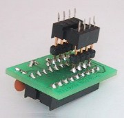
THE ADAPTER
SOCKET - type B
This adapter is available as a kit containing the two IC sockets, a
small PC board, two components for the RC oscillator and an 8-pin header
to connect the 8-pin IC socket to the adapter. The adapter can also
be "fabricated" by using tinned copper wire and two IC sockets.
It will allow a PIC16F84 to be plugged into a project designed for a
PIC12C508A, so you can create a program.
The adapter is a bit top-heavy but it does the job perfectly.
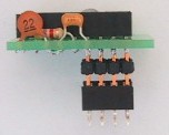
The 508A has a built-in 4MHz oscillator and so the two oscillator components
for the PIC16F84 must be added as shown in the diagram.
By fitting a PIC16F84 to the socket, you have a PIC12C508A!
It takes a
little bit of skill to solder to the 8-pin socket without damaging the
plastic surrounding the pins but with a fine-tipped soldering iron it
can be done.
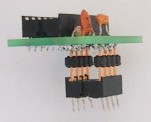
Keep the sockets 1cm (3/8") apart to make it easy to get the soldering
iron tip onto the lower pins.
The 4k7 and 22p are mounted in the space under the 18-pin socket.
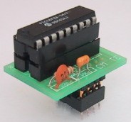
The adapter socket is available as a kit and is made on a small printed
circuit board as shown in the photos below:
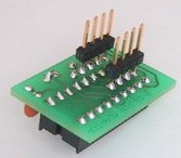 Underside of adapter |
  The 8 pin socket is pushed onto the header pins |
 |
 |
|
Completed adapter
|
Adapter with chip fitted
|
WRITING
A PROGRAM
The program we have written for this project uses the 35 instructions
supplied by the manufacturer of the chip.
This is called the "lowest" form of programming as there are
other ways to program the chip using instructions that sometimes perform
a more-complex operation with a single command. This type of programming
is called "high level" or "higher level" as it is
"distant" from the actual instructions carried out by the
chip.
These "higher level" languages are supposed to be easier to
understand and easier to work with.
This is (can be) true, but the object of this project is to show how
to program a chip in the cheapest, simplest way.
Some of the things we do in our other projects appear to be very simple
but some sub-routines are checking and setting flags etc and the order
of these operations is very important. And it is very important that
you have control over where these instruction are placed in
a program. High-level languages may or may not produce instructions
in the order you intended.
Everything is wonderful until a fault develops and that's when you appreciate
the ability to see the whole program laid out in the same way it will
be executed by the micro.
The author only takes on a project or design if he knows he can complete
the task without any external input. And that's what you should do too.
That's why the "hand-assembly" approach has been presented.
You can see exactly what is happening.
Once you learn the 35 instructions
you can perform absolutely every task the micro is capable of carrying
out. Not only this, but the program will occupy the smallest amount
of memory and you can visually fault-find the program.
This approach has been successful up to a 1,000-instruction program
(about 15 A4 pages!). Believe me, a 1,000 line program is quite complex
as many of the previously-written sub-routines can be CALLed and the
program gets more powerful as it builds up.
We will let you know when this approach gets too difficult to handle.
Until that time comes, our approach has been shown to be the only way
to learn programming, and is an ideal way of creating a project or product
for commercial sale.
![]()
The adapter fitted to Robot Beacon while
creating the program.
THE PROGRAM
The program has a simple
"linear" layout with the micro advancing down the program.
There are no sub-routines. The only loops are the delay routines and
the loop at the end. This loop checks the illumination on the photo
darlington transistor. Light falling on the device will cause it to
conduct and the voltage on the input line of the micro will be low.
The micro looks for a HIGH on this input line to cycle Main. Otherwise
it remains in a loop at the end of Main.
The diagram below shows how the program flows:
![]()
The following program is "burnt" into a PIC16F84 and the chip
is fitted to the project via the adaptor socket described above. The
instructions in SetUp (such as TRIS 06 and OPTION 0DFh) are for the
PIC12C508A but do not upset the operation of the PIC16F84. Don't worry
about the comments generated by MPASM when using TRIS. The instruction
"GOTO Main" is not needed but it shows what is happening in
the program. It also allows routines to be placed between SetUp and
Main.
|
||||||
Once the project is working perfectly, a PIC12C508A chip can be burnt.
Make sure the settings are changed on MPASM and IC-Prog to suit the
508A chip. The .hex file Bcon508A.hex can be found in
Beacon Files.
|
||||||
If the operation of the program in a PIC12C508A is not exactly what
you want, a second "burn" can be carried out by referring
to Try2-508.asm The program has been located 110 bytes
down memory. It has 110 NOPs above the program and ORG 0
is removed.
|
||||||
Before using this program, two things have to be remembered.
Read the chip you want to re-burn by placing it in the Multi Chip programmer
and click the "IC icon with the arrow emerging from it." Make
sure memory at 6Eh onwards is unburnt (contains 3FFh). If not, add NOPs
to your program to push it further down memory.
Make sure the program you are re-burning does not extend past the end
of memory (511 bytes). This is highly unlikely, but must be taken into
account when using Try4-508.asm as the program has been pushed
400 bytes down memory and only a 110 byte program can be burnt.
You will notice Try3-508.asm has not been supplied. It burns
a program at approx 300 bytes from the top of memory. These are concepts
you can work with yourself and will depend on the number of bytes in
a program.
The files in Beacon
Files
are:
Beacon-1.asm Beacon program at the top of memory
for a PIC16F84 chip - also .hex
Bcon508A.asm Beacon program at the top of memory for a
PIC12C508A chip - also .hex
Try2-508.asm Beacon program at 110 bytes down
memory for a PIC12C508A chip
Try4-508.asm Beacon program at 400 bytes down
memory for a PIC12C508A chip
GOING FURTHER
The program we have written can be changed or modified in any way and
the concept of re-burning can be applied to any other program you are
developing.
It can be modified to take an audio input as well as light-detection,
on a single input.
The circuit below shows how to connect the two detectors to the input
line:
![]()
Audio and light on same input-line
The
first transistor is a standard audio amplifier but the second stage
converts analogue signals into a digital signal. The operation of these
stages has been discussed in the PIC
LAB-1 project.
The display can be activated or reversed when it detects audio and shut-down
when light is detected.
You will need to write your own program for this. You will need to differentiate
between a constant LOW and LOW-PULSES. If the input is LOW for a long
period of time, the photo transistor will be detecting light from the
surroundings. If the input is receiving pulses, the program will go
to a different routine.
The detection-routine can be contained inside a delay routine.
Use this project to advance your programming skills and you will come
up with something you can say: "I designed this!"
![]()