The
SOLAR
ENGINE
CIRCUIT
P1
P3
P4
P5
P6
P7
P8
P9
P10
P11
P12
![]()
A solar engine circuit is a control circuit that takes micropower (milliamps of current) and converts that micropower into more powerful pulses. These more powerful pulses are usually used to power motors, but can be used to power other motion-creating devices, such as, Nitinol wire. (See the full project on this amazing wire by clicking HERE).
The first SOLAR ENGINE was built by Mark W. Tilden in late 1989. Let's describe the circuit.
In BEAM folklore there are three types of SOLAR ENGINE:
Type 1: Voltage based. This is your standard circuit for: Photopopper, FRED, Suneater etc.
Type 2: Time based. This is trickier to do, since the changing voltage affects the time constants of your SE. The only type 2 SE that I'm aware of is the one inside a miniball - and it's not for the faint of heart.
Type 3: Current based. This SE turns on when the current going into the capacitor drops below a certain threshold. This SE has been a bit of a 'Holy Grail' for designers, because the SE will adapt to the specific solar panel/cap/light level that you have available. In bright light (lots of current) the SE will turn on at a high voltage, and in low light it will turn on at a much reduced voltage, because there isn't as much current available.
THE SOLAR ENGINE
CIRCUIT Type-1:
Theory of Operation
This circuit is the basis of BEAM (Biology, Electronics, Aesthetics, Mechanics) robotics philosophy. It is an energy storage circuit known as a Solar Engine(tm) (abbreviated SE). This design is called a Type-1 SE. Low current from a solar cell is stored in a large capacitor and when a preset voltage-level is reached, the energy from the capacitor is released to a motor.
The circuit starts by charging the electrolytic.
The voltage across the electrolytic rises. The two transistors are turned off at the moment and they can be considered to be absent from the circuit.
The only three components "in circuit" are the diode, 1k8 and motor.
Next, the voltage across the diode rises to 0.7v and stops at this level. This is the characteristic voltage across a diode. It is called its forward voltage drop.
(the resistance of the motor is very small and we can neglect it for the moment.)
As the voltage across the electrolytic rises, the voltage across the 1k8 resistor starts to increase.
This voltage also appears across the base-emitter junction of Q1 and when it reaches 0.65v, the transistor begins to turn on.
This creates a low resistance between the collector-emitter terminals of Q1 and allows current to flow into the base of Q2.
The voltage across the electrolytic rises slightly more and this causes Q1 to turns on harder.
This effectively makes Q2 turn on a lot harder and now a very high current is able to flow through the collector-emitter terminals of Q2. This current causes the motor to spin and the energy from the electrolytic is released to the motor. Q1 was originally turned on via the diode but now the voltage across the diode falls below 0.7v and Q1 is kept on by the voltage across the motor being passed to the transistor via the 1k8 resistor.
As the energy is released from the electrolytic, the supply voltage falls and when the voltage across the motor is less than 0.65v, Q1 begins to turn off. This action turns off Q2 and the motor stops.
The cycle then repeats.
The solar cell must produce a voltage greater than 0.7v + 0.7v = 1.4v so that the electrolytic will charge. If you add an extra diode in series with the 1N 4148, the solar cell (panel) will need to produce a higher voltage.
A Note from the Author
There seems to be a lot of questions and problems in replicating the circuit above. Steven Bolt of the Netherlands has come up with a potential solution called SunEater. This is the next circuit in our discussion. The best advice, from my experience, is to make the circuit above using the values given. Experiment with it. If you still have problems, a good course of study for those just beginning in BEAM robotics would be to start out with a solar engine based device, before moving on towards more complicated circuits, such as nervous networks, like the microcore.
Relevance to Nervous Networks
The Solar Engine(tm) is just a transistor implementation of a Nv "Monocore" that can drive a motor directly without the need for additional buffering (as in the more complicated Nv Networks).
In fact a SE behaves very much like a nervous network. The SE has an upper threshold (trigger voltage) and a lower threshold (shut off), and the duration of the state change (pulse) is directly affected by the motor load. In addition the "off" state (really the time held below threshold) is affected by what's feeding it (in this case the solar cell/trigger, in a nervous network - the previous Nv). So, in essence you have a quasi-chaotic phase/state-based oscillator threshold device that is self-attenuating with respect to environment in a dynamic fashion. See the FAQ for details on Nv Networks (NvNets).
Parts
When first building a SE, use the parts recommended. Experiment with substitutions once you have a working circuit.
M - a motor. Motors with small power requirements usually work great (i.e., 3 volts at a low current rating). (A word of warning: some small recorder motors have a built-in capacitor of about 20 nanofarad. The 2-transistor FLED SE won't work with such a motor - it will start to oscillate, sometimes audibly. Without a scope, the typical symptom is `hangup' in reset. The SE fires once, then stops, the voltage on the storage cap remaining at less than 1.0v. Both SunEaters are immune to this problem, and will run such motors.)
C1 can be anywhere from 2,200µF to 47,000µF (or as high as 10 Farad). Depends on your application and timing requirements.
R1 can be anywhere from 1.8k Ohms to 15k Ohms. The smaller the resistance the better the starting power of M, but more energy is lost in the transistors.
Q1 - a PNP transistor, general-purpose like the 2N2907, 2N3906, etc. Also cheap and easy to find.
Q2 - a NPN transistor, general-purpose like the 2N2222, 2N3904, etc. Cheap and easy to find.
D1 - a threshold device, such as a small signal switching diode, e.g., 1N4728 to 1N4731. Since a single diode triggers at [0.6 - 0.7] volts, you can use multiple diodes in series to obtain a higher voltage. Arranging the diodes in series will give an increased increased "trigger" voltage, thus two diodes will trigger at [1.2 - 1.4] volts and three diodes in series will trigger at [1.8 - 2.1] volts.
Solar Cell - like a 24x33mm Sunceram. Purchase solar cells with the highest current output for best results.
Construction
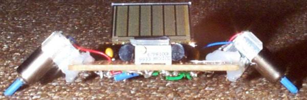
For those that are good at soldering, the circuit is best put together in a free-form kind of structure, that is, without any circuit board. See this alternative set of plans (called Solaroller) and picture below depict the physical layout of the solar engine-the layout is right above the circuit diagram. I believe it is the best layout, and does not require a printed circuit board (PCB). As for the mechanical layout, the best advice I can give is to start building, because your first will not be your best. When you have completed your mechanism, don't rat-it for parts, move on to the next so that you can have a living history of your projects.
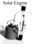
A solar engine using the free-form
layout without a PCB (without motor)
Making your own solaroller
The Solar Engine Circuit above is the heart of many solar-powered robots. It is called the BEAM SOLAR-ENGINE. The idea is that available solar cells do not supply enough power to overcome friction in a typical robot design. So the power is stored until enough is available and then used to operate a small motor. The result is a continuously operating (well, as long as there is light) drive system. When coupled with a clever design, it can produce robotic "plankton" which displays emergent behaviour.
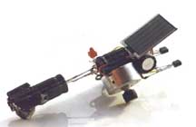
The original circuit was developed for the Robot Olympics and used in a Solaroller device, similar to the one in the pictures below. It covers one 1 metre in one minute, in very good sunlight using only a solar cell 2-1/2" by 1/2".
 Click
on the thumb nail of a Solar Engine circuit using a UJT and
SCR to do the same job as the Solar Engine described above. This circuit shows
how you can solve a simple task with a complex approach and using expensive
components!
Click
on the thumb nail of a Solar Engine circuit using a UJT and
SCR to do the same job as the Solar Engine described above. This circuit shows
how you can solve a simple task with a complex approach and using expensive
components!SUN EATER I by Steven Bolt
An improved design for a type-1 circuit is the Sun Eater. It has a very clever 2-transistor self-latching arrangement that keeps the circuit ON until the voltage drops to 1.5v. The circuit turns on at 2.8v. This gives the motor more energy from the electrolytic at each "pulse" than the Solar Engine circuit above.
This circuit is also a voltage-controlled design. It turns on when the voltage across the electrolytic reaches
a certain "threshold". But the advantage of this circuit is the
"hysteresis" or wide difference between turn-on and turn-off. The
circuit turns on at 2.8v and turns off at 1.5v. These levels are important as
they control the amount of energy delivered to the motor during each
"pulse."
The Sun Eater robot constructed by the author with this circuit is shown below.
It requires two of the Sun Eater circuits.
The clever "latch" section of the circuit is made up of transistors
Q1 and Q2. The secret to the operation of the circuit is the feedback line shown on the diagram.
Everything is off at the beginning of the charge cycle and the only components
to be considered are the 100k, green LED and base-emitter
junction of Q1.
As the voltage on the electrolytic increases, the LED begins to pass current
when the voltage across it is 2.1v. The voltage on the base of Q1 rises and
when it is 0.65v, the transistor begins to turn on. This begins to turn on
transistor Q2 via the 470k resistor and a voltage appears across the two 470k
resistors in series. The supply voltage at this time is approx 2.8v
When the voltage at the join reaches 0.7v, transistor Q1 is turned on harder
and now the voltage on the electrolytic does not have to rise any further for
the circuit to turn on more and more.
Transistors Q1 and Q2 keep turning each other ON more and more by an action
called positive feedback and this causes transistors Q3 and Q4 to get turned
on
fully too.
The whole circuit is fully turned on and the energy from the electrolytic is
passed to the motor.
As the voltage across the electrolytic drops, the circuit remains fully turned
on until a point is reached when the voltage on the lower 470k resistor is less
than 0.6v. This is when the circuit begins to turn off. The supply voltage
at this time is 0.6v + 0.6v + 0.3v (the voltage collector-emitter of Q3)
= 1.5v. This gives a hysteresis value of 2.8v - 1.5v = 1.3v
With a single green LED to determine the switch-on level, the motor will start
when the 47,000µ cap reaches 2.8V, and stop when the voltage drops below 1.5v.
This gives good economy for pager and small recorder motors. If your motor
needs a higher voltage, you can put a diode in series with the green LED. Each
diode will increase the voltage by 0.7v.
This circuit can be called Sun Eater IA as it is an improvement on
the Sun Eater I circuit shown above. It works exactly the same except
the slight re-arrangement of the components allows an NPN power transistor to
be used. One less resistor is needed and one less capacitor but two extra
diodes have been added to increase the upper turn-on voltage.
The prototype layout on a PC board is shown below.
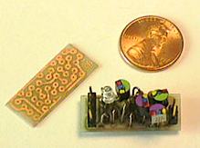
It is very compact and has connectors for the electrolytic, power and motor. The PC board provided in the kit is pre-tinned and has an overlay on the top to identify the placement of each component. Click below to order the kit. You will need a motor and solar cells to generate at least 3v. The kit comes with a 1,000u electrolytic.
THE SOLAR ENGINE CIRCUIT Type-3
Type-3 circuits are current controlled or current-triggered. This is another
very clever way of detecting when the electrolytic has reached its maximum
charge.
At the beginning of the charge-cycle for an electrolytic, the charging current
is a maximum. As the electrolytic becomes charged, the current drops. In the
type-3 circuit, the charging current passes through a 100R resistor and creates a
voltage drop. This voltage is detected by a transistor (Q2) and the transistor is turned
ON.
This action robs another transistor (Q1) from turn-on voltage and the rest of
the circuit is not activated.
As the charging current drops, Q2 is gradually turned off and Q1 becomes turned
on via the 220k resistor on the base.
This turns on Q3 and the motor is activated. The voltage across the storage
electrolytic drops and the current through the 100R rises and turns the circuit
off. The electrolytic begins to charge again and the cycle repeats.
Click HERE
for descriptions and photos of a number of solar robots from BEAM ONLINE. These
photos show the variety of designs that can be created with SOLAR ENGINE
circuits.
For an excellent set of photos on BEAM Solar Robots, click HERE - Scott's Robotics Page.
Page 3 covers the semiconductors used in Robotics.
Page 4 covers more Solar Engine circuits and the use of photo-detectors to
detect light source.