ROBOTICS
and
AUTOMATION
Page 4
Combining the Solar Engine Circuit with Photo detectors . . .
The Solar Engine Circuit can be combined with light-detecting
devices so that a Robot can move towards or away from a light-source. This adds
realism to its "artificial intelligence."
The simplest Photovore is called Solar Photovore displayed on Lee's
RoboGallery page.
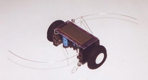
The photos below show how the Robot has been designed:
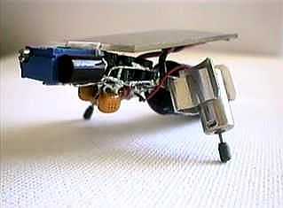
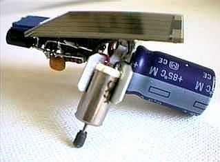
The circuit for this robot consists of two Solar Engines with 1381J voltage detector IC's (digikey part #MN1381-J-ND) and two photo diodes
(digikey part #LT1032-ND). These photodiodes cause the Solar Engine on the opposite side to fire and the Solar Photovore turns toward the light source. The motors are two pager "vibe" motors with the weights removed, from Solarbotics type Namiki 1701. The 100k potentiometer on the "head" balances the two Solar Engines.If you want a full kit with all required parts and a very high quality PCB, go to Solarbotics.
Here is the layout as shown on Lee's RoboGallery site:
Adding
Feelers
You can add feelers to the project above by connecting them to the circuit
as shown in the diagram below:
If you are unable to get the 1381 Voltage-reference IC's, here a circuit that uses LEDs to detect the trigger voltage:
![]()
Photovore by PiTronics
Now we come to another Photovore Robot using a very clever clock mechanism for
the motor. The clock mechanism is taken from an old clock or can be purchased
separately from hobby shops. These are often in the hand-craft section for those who like to make their own clock
faces.
The animation below shows how the Photovore described in this article avoids obstacles without needing
to reverse.
This animation has been taken from PiTronics
Photovore site - by S Bolt.
This Photovore was designed and built by S
Bolt. Note the way the feelers are connected.
The Photovore Robot shown above uses two clock mechanisms to
drive the wheels. The clock-motor is normally driven from a 1v5 cell and pulsed
every second when used as a clock. But the "motor" speed can be
increased in RPM to provide rotation for a robot. A 30:1 reduction drives the "seconds" hand and this
is used to drive either the left-hand or right-hand wheel (two mechanisms are
needed). The clock mechanism is taken apart and the chip,
plus some of the gears are removed.
The motor is then fed pulses from an oscillator from the electronic circuit
shown on the next page and the RPM is increased to produce
an output of about 17RPM.
See the circuit for the Photovore Robot on the next page.