|
The Servo |
|
|
You need to read ALL of this article as TALKING ELECTRONICS has
a number of projects using a servo and they all have different features,
different capabilities
and different prices.
WHAT IS A SERVO?
A servo is a motor and gearbox and connected to the output shaft is a potentiometer that feeds a signal back to the electronics.
The operator sends a digital signal to the servo and the waveform has a varying length of HIGH. This signal is repeated 50 times a second and the electronics in the servo compares the length of the HIGH with the signal coming back from the pot. When they are the same, the motor stops. The servo is very fast to respond and it takes less than a second to get to the new position.
For some applications, the servo rotates too fast and it can only rotate about 270 degrees. These are two limitations of a STANDARD or NORMAL or ORDINARY or unaltered SERVO. The other type of servo is called a CONTINUOUS ROTATION servo.
For some projects you want to rotate a pot and have the servo correspond. This is called SLOW ACTIVATION and requires a project that has been designed for this.
All these things have been addressed with Talking Electronics projects, plus a number of other interesting features.
Many of the projects come with a servo because some servos respond better than others and some servos have arms that do not fit! We have tested all out servos for suitability for each project and made sure the arms fit.
In addition, you can get a linear servo that outputs in a straight line for about 2cm. These actuators are quite expensive, but they are very small. They detect the same signal(s) as an ordinary servo and provide the same relative positioning and the travel is fast. Mid-position of travel is 1.5mS for every servo. This is a "standard."
The rotational output of servo can be converted into linear motion with
the aid of a crank:
There are also servos that
rotate 360 degrees, called a Continuous Rotation Servo:What is a Continuous Rotation Servo?
A continuous rotation servo is one that does not have a limit on its range of rotation. Instead of having the input signal determine which position the servo should rotate to, the continuous rotation servo detects the input signal and creates a corresponding speed of the output shaft. Moving the pot in the other direction, past the mid-point will rotate the output in the opposite direction. For example, a PWM signal of 1.5mS stops the servo. A PWM signal of 1.0 will turn the servo full-speed in the clockwise direction and a PWM signal of 2.0 will turn it full speed in the counter-clockwise direction. Values in between 1.0mS and 2.0mS will turn the servo at a lower speed.
| Input | Rotation Speed (%) | Direction of Rotation |
| 1.0 | 100 | Clockwise |
| 1.1 | 80 | Clockwise |
| 1.2 | 60 | Clockwise |
| 1.3 | 40 | Clockwise |
| 1.4 | 20 | Clockwise |
| 1.5 | 0 | Output Stopped |
| 1.6 | 20 | Counter-clockwise |
| 1.7 | 40 | Counter-clockwise |
| 1.8 | 60 | Counter-clockwise |
| 1.9 | 80 | Counter-clockwise |
| 2.0 | 100 | Counter-clockwise |
There are a number of points that need to be understood when ordering
a Continuous Rotation Servo from a manufacturer or from eBay.
1. They are expensive, and
2. You can make your own. See below.
The simplest way to get a servo to operate is via the following two
circuits. They use a 555 and a few surrounding components.
All the projects described in this article use this basic concept of
producing a mark-to-space ratio of 1mS to about 2mS every 20mS to
operate a servo. The kits are easy to assemble and allow you to build something
complex. It just takes thinking and the ability to combine electronics
with hardware.
of 1mS to 2Ms every 20mS
What do you want to do?
There are lots of things you can do with a servo.
Talking Electronics has projects that cover many requirements . . . such as reducing the
speed of rotation or limit the amount of travel.
And a project
that turns an ordinary servo into a continuous servo.
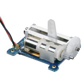
We also remove the PC board from inside the case of a servo and turn it into a Motor and
Gearbox by connecting directly to the motor.
This becomes the cheapest and smallest reduction-drive you can get.
You can get a servo with plastic gears for light-duty" or metal gears for long-life.
"
But you need to read this article fully to work out what you can do and
how you can adapt a servo to your requirements.
1. Rotate a servo via a switch
SERVO DRIVER K-SD1 $15.40 provides control to one or two servos via toggle switches.
The board is divided into left-side for servo 1 and right-side for servo 2.
For the left-side you only need 2 mini trim pots. One is used for the limit of rotation clockwise and the other for limit of rotation anticlockwise.
Servo's are $2.50 extra Postage is $4.50 for Australia $6.50USD overseas
The rotation is very fast (less than 1 second) and if you want slow or very slow action, Talking Electronics has another project, see below.
The PC board with all components fitted:
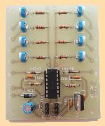
The mini trim pot determines the number of degrees rotation. Make sure it is at a position that is less than the "end-stop" of the output shaft, otherwise the out will jam and prevent the arm moving in the other direction.
The wiring diagram for one of the servos:
When using a toggle switch, you do not
need the top two mini trim pots on the PC board.
The .pdf of the project is here:
http://www.talkingelectronics.com/EMR-2/ServoDriver.pdf
You can replace the switch with a larger pot and move the output arm of
the servo at a slower rate.
The original Circuit where the servo
simply rotates from
one limit to the opposite limit.
The modified Circuit where the servo follows the
rotation of the pot.
To control each servo via a pot, simply connect the middle and end tabs of the pot as shown. The top 10k may have to be adjusted to get the end position you want.
2. Rotate a servo via a pot
REMOTE BOOM GATES project allows you to rotate the output shaft of one or two servos at the same time and producing the same angular displacement, as you turn a potentiometer.
A kits of parts, module (CCPM Servo Master) with pot and knob, 2 servos, 2 x 3m extension leads and 2 Boom Gates (miniature plastic working-models) 2 x 0.6mm stiff wire for linkage between servo arm and Boom Gate and 2 x pins for Boom Gate. $22.00 plus $4.50 postage.
It can be used for projects such as operating BOOM GATES or many different types of animation.
It uses a pre-built module containing the pot and 2 outputs for the two NORMAL servos and a PC board for the power supply. The REMOTE BOOM GATES kit comes with 2 servo's and components for a 3-metre extension lead for each servo. The PC board converts a supply voltage of between 9v and 15v DC to 5v DC for the operation of the module and servos. 4 mounting holes are provided or you can use double-sided tape to hold the project to your base-board.
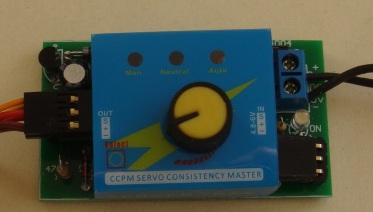
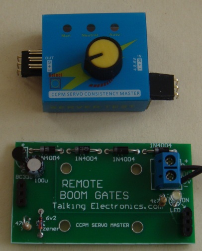
The SERVO TESTER module removed from the PC board to show
the components on the board. Two 90° connectors
hold the module in place. One connector is only a dummy.
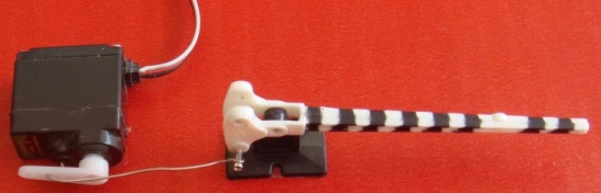
The servo is fitted into a Platelayers hut:

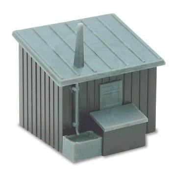
Platelayers hut
The
REMOTE BOOM GATES
project
will drive 2 servos and the servo above will connect directly to the 3
output pins on the left hand side of the project. (There are two sets of
3-pins.)
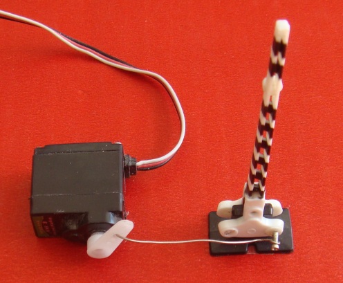
Make sure both servos are in the same starting position, by moving the
arm by hand, and rotate the pot to raise and lower the Boom Gates.
All you need is a linkage between the arm on the servo and a pin on the
Boom Gate. The pin and linkage are provided in the kit.
2a. Operate a Point
-
slow action
REMOTE BOOM GATES
project can be used to operate a Point on a Model Railway layout.
The Remote Boom Gates project has two outputs and two Points can be
operated at the same time.
Turn the pot on the project to active 1 or 2 points
at the same time.
2b. Operate a Gripper
REMOTE BOOM GATES
project can be used to operate a gripper. See the following images for a
gripper produced by Talking Electronics.
The gripper comes as a partially cut-out set of parts and you will need
a file and sandpaper to finish the edges and assemble the parts
with the nuts and bolts provided.
The Gripper takes a SG90 Servo by Tower and an extension lead is provided
in the kit.
SG90 Servo $2.50
Photo of Gripper
They are being made at the moment.
Expected date: 30th September 2017
Converting a Servo for Continuous Rotation
A "normal" Servo can be converted to produce continuous rotation and
tested on the
REMOTE BOOM GATES
project.
The servo will stop when the pot is in the mid position and rotate
clockwise very slowly when the pot is turned slightly. It will increase
RPM as the pot is rotated.
It will turn in the opposite directions when the pot is turned to the
left.
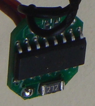
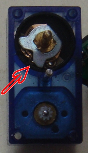
The servo needs to be modified and the pot inside the housing has the 3
wires removed.
Two 2k7 (272) surface-mount resistors are soldered to the 3 lands on the
PC board and this will put a mid voltage on the middle land so the
electronics "thinks" the pot is in the middle or "centre" position.
When the project sends a signal equal to 1.5mS HIGH, the servo will not
rotate. A wider or narrower HIGH will rotate the output shaft and the
direction and RPM will vary according to the position of the pot on the
Remote Boom Gates project.
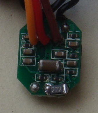
the underside as there is not enough room for both on the top.
The "stops" on the inside of the case of the pot must be scraped with a knife so the wiper can
rotate fully without interference. The fingers that contact the carbon
track must also be pulled off the track with a fine screwdriver so the
wiper can move freely.
The pot inside the case does not do anything. But it has a shaft that is
used by the COMPOUND GEAR-BOX and cannot be removed. It has a flat on
the end and rotates in accordance with the output gear and thus it must
rotate freely.
removed so the pot can rotate freely
Finally the stop(s) on the output shaft (gear) must be snipped off with side-cutters so the gear rotates freely.
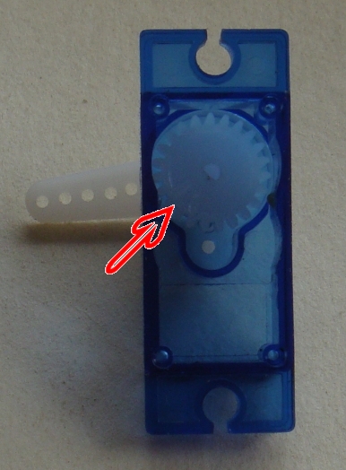
with side-cutters
Assemble the servo and you will be able to rotate the shaft 360° by hand
to prove to rotates freely.
Connect the servo to the
REMOTE BOOM GATES
project and turn the pot. The servo will respond.
The modified servo can be used in the project:
Servo Tester
- test a servo
4. Use a Servo for
Animation
The
REMOTE BOOM GATES
project can be used to test a servo.
It can be used to test a NORMAL SERVO (a non-modified servo) and a servo
that has been converted for CONTINUOUS ROTATION.
The module on the Remote Boom Gates PC board has a pot with a
knob and 3 modes of
operation. A pressure switch on the left-side of the module changes the
settings. This switch is under the plastic and cannot be seen.
The module comes ON and allows a normal servo to follow the position of
the pot. A Continuous rotation servo will rotate at the prescribed RPM.
(It will rotate forwards and/or reverse at a slow or fast RPM).
No push the switch. The second function will cause a normal
servo to rotate to the neutral position and stop. A continuous servo will
rotate slowly and the pot will have no effect.
The third position will cause a normal servo to swing fully clockwise
then fully anticlockwise and repeat the action all the time.
A continuous servo will swing about 2 turns in one direction then
reverse direction
about one turn and repeat the action.
3. Use a Servo to
operate a point
- fast action
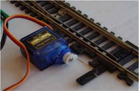
Used in model railway layouts to operate a point via
a normal servo with linkage from the servo to the lever on the point.
This project allows you to manually operate a point via a
SPDT toggle
switch.
Our project uses a normal SERVO, for the activation of the point. this project limits
the rotation to about 90 degrees and this is enough to move the rails at
the point via a rod called a "linkage." The action is fairly
rapid.
An "arm" is fitted to the output of the servo and a
short push-rod from the arm to the rails.
The kit comes with the servo, switch and linkage wire.
Point Controller using 555 IC
Complete kit with servo $10.00
plus $6.50 postage. Pre-assembled and tested project is $5.00
extra.
Point Controller using 555
circuit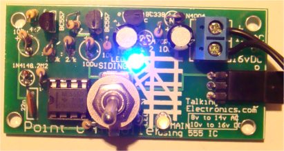
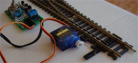
The servo connected to the
point via a stiff 0.6mm wire.
Slight "give" in the wire allows the servo and
lever on the point to align.
This project allows you to control the movement of a normal servo and it
stores the action in memory so it can be repeated AUTOMATICALLY.
Removing the electronics from inside the servo and connecting two wires directly to the motor creates a very powerful output shaft from a motor and gearbox. It is very compact and very cheap. You can get a metal-gear version if you want to use it for a long period of time.
It has also been converted to rotate 360 degrees and thus you lose the ability to stop the shaft at a particular angle. But you can't have everything !!
If you drive the motor with either a low voltage or pulses of energy, you can reduce the speed of rotation of the output shaft and use it for lots of different projects.
That is what we do in the projects.
More to come . . . . . . . . .
18/8/2017