|
THE WASP |
|
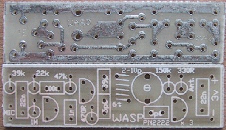
The PC Board Artwork for The Wasp |
|
SENSITIVITY The sensitivity of the WASP depends to a large extent on the value of the load resistor on the electret microphone. We have used 39k in the project, as the microphone we supply is a very sensitive type. If you wish to increase the sensitivity to super performance, the resistor can be decreased to 33k but don't go any lower otherwise the circuit may 'oscillate' or 'motor-boat.' Three leaded microphones can be used in the circuit by connecting the earth lead to the negative rail and the centre lead to the load resistor on the PC board. This means the resistor inside the microphone is not used. Don't try to open up any of the microphones as they contain a FET transistor and a metallised plastic diaphragm (and nothing else) and they will not work satisfactorily on reassembly. Some electret microphones are larger than others. They all work on the same principle and produce an output waveform when supplied with a voltage. But some produce a very high output while others are extremely poor. There is no way to find out the difference without putting them into a circuit. The size of the waveform is governed by the quality of the electret material and there is nothing you can do to change this. Electret microphones DO NOT PRODUCE a voltage or current but rather modify a voltage across a load resistor. This is why you must have a load resistor in series with one of the leads. If you put a microphone directly across the power rails, it will be damaged. It is an active device (due to the presence of a FET transistor) and must be placed in a circuit around the correct way. Some microphones come with long leads and can be soldered directly to the board. Others will need short leads added to them and when doing this, do not overheat the microphone as the diaphragm is very easily damaged. If the microphone produces a lot of background noise, like bacon and eggs frying, it is damaged. The most likely cause is overheating during soldering. The only thing to do is get another electret insert and solder it more carefully. Keep your fingers on the body of the microphone to monitor the temperature rise. If it gets more than slightly warm, the electret material inside the case will lose its electric field and become damaged. Early electret microphones could not be left out in the sun without damage - so you can see how sensitive the electret material was. |
 |
|
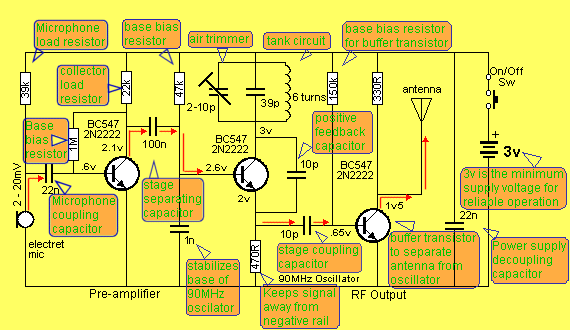
The name of each component and the signal through the circuit THE FUNCTION OF EACH COMPONENT:The electret microphone picks up sounds and produces a 2-20 millivolt signal. The 39k microphone load resistor determines the gain of the microphone. The 22n couples the microphone to the input of the first stage. The first BC 547 provides a gain of about 70 for the audio signal The 1M and 22k bias the transistor so that the collector is at half rail voltage. This gives the stage the highest gain. The 100n passes the audio to the RF oscillator. The 1n keeps the base of the RF oscillator stable for the 90MHz oscillator. The 47k turns on the RF oscillator. The 470R allows feedback via the 10p to the emitter to keep the oscillator working. The 2-10p trimmer 39p and 6 turn coil form a tuned circuit to govern the frequency of operation. The 10p on the emitter taps off a small portion of the signal and passes it to the output stage. The third BC 547 acts as a linear amplifier and keeps the loading effect of the antenna from the oscillator. The 150k base bias resistor turns on the output stage. The 170cm antenna is a fair approximation for a half-wave antenna for 90MHz operation. The 22n prevents the positive rail from rising and falling as current is drawn by the oscillator and output stages. It keeps the two rails rigid or ōfixedö It keeps the circuit working at peak performance when the batteries have started to weaken. The 3v supply is the lowest voltage needed for reliable operation and good performance. |
|
HOW THE CIRCUIT WORKS The circuit is fairly complicated and to help you understand the function of each component we have provided a second circuit diagram with each component labeled. The first component we will talk about is the electret microphone. This is a device containing a Field Effect Transistor (FET) and nothing else except a diaphragm made from a thin plastic material that has been charged in an electric field. This produces a static electric field that remains on the plastic after the energizing field has been removed. This is called electret material and is metallised so that the charges move more readily over the surface. The input lead of a FET (the gate) is connected to a thick metal disc placed close to the plastic diaphragm so that as sound waves enter the microphone they move the diaphragm slightly and influence the charges on the metal diaphragm and these move in and out of the gate lead of the FET. The charges on the electret material do not enter the FET they merely influence the charges on the metal disc. The Field Effect Transistor is a high impedance device and does not inhibit the movement of the charges. The FET amplifies the charges to produce an output at the drain lead. A 39k load resistor is connected to this lead and its value determines the gain of the FET. If you decrease the value of the resistor, the output increases, but at the same time the background hiss and noise may increases and a compromise has to be made between sensitivity and noise. We have selected the most suitable value of load resistor for the electrets we are supplying in the kits. If the resistor is decreased too much, the front end will generate a problem of instability and produce a loud squeal in the receiver - that's why it is best to keep to the value we have suggested. If you are using the project as a handŁheld wireless microphone, the resistor can be increased to 68k or higher so that you can speak directly into the microphone without producing distortion - see notes at end of the article on hand-held microphones. The next component is the 22n capacitor. It couples the microphone to the first audio stage. This value is not critical however it should be as large as possible to pass the low frequencies. 22n is the highest value available as a ceramic in a small package. The next section we look at is the audio amplifier. It consists of a transistor and two biasing resistors. To keep the stage separated from the other sections of the circuit it has a capacitor (22n) at the input and a 100n at the output. This makes it an AC coupled stage. The main purpose of this stage is to provide gain for the microphone so that the microphone does not have to be overdriven. This will keep the backŁground noise to a minimum. The transistor is biased via a 1M base resistor and provides a gain of about 70 to 100. The output coupling for this stage can be any type of capacitor and we have opted for a 100n monolithic (monoblock or multi-layer capacitor) for its small size. The next stage is a high frequency oscillator operating in the 100MHz region. The actual frequency depends on the value of the coil and capacitor in the tuned circuit, and elsewhere in this article we have given information for setting the frequency. With the values supplied in the kit, the frequency is approximately 90MHz and this can be increased or decreased a few MHz by spreading or closing the turns of the coil. Spreading the turns increases the frequency and compressing them decreases the frequency. The frequency can be further adjusted after the project is complete, by turning the air trimmer with a small screwdriver. This will give an adjustment of about 5 Mega Hertz. Moving the vanes out of mesh increases the frequency and moving them into mesh decreases the frequency. The oscillator is a voltage-controlled oscillator and this means the voltage of the supply will have an affect on the operating frequency. We are assuming the supply is stable when making and testing the project and we consider the oscillator to be stable as far as the supply rail is concerned. This will be the case when the batteries are new. As the batteries near the end of their life, the frequency will shift slightly. Good quality AAA cells are supplied in the kit but if you want additional life from the transmitter and greater long term stability of operation, you can use alkaline cells. These will give about 200 hours of operation. Other components in the circuit affect the frequency but these have only a minor affect. However, if some components are removed from the circuit, the oscillator will not operate at all. Some of these components are a long way away from the oscillator however their influence can be quite dramatic. For instance, removing the 1n on the base of the oscillator or the 22n across the battery will have a major effect and the oscillator will either not work or have a very low output. We don't suggest any values be changed or the layout altered in any way as the performance of the Wasp has been perfected after many prototypes and any deviation may lead to failure. For instance, moving the tuned circuit (the coil, capacitor and air trimmer) as little as 1cm away from the collector lead of the transistor will decrease the output by 50%. The additional length of the track-work will reduce the feedback pulse to the emitter of the oscillator stage and it may not produce reliable start-up. In a similar way, a project such as this built on matrix board or strip board will perform very poorly due to the open layout. ThatÆs why I only recommend the circuit being built on one of the printed circuit boards supplied in the kit. It has been designed as tight as possible to give the best performance. Getting back to the oscillator stage: It is turned on via the 47k resistor and this causes current to flow in the collector-emitter circuit. Connected to the collector is a parallel tuned circuit made up of a capacitor and coil. When a pulse of energy is passed through an arrangement such as this, the capacitor initially absorbs the energy as it has the lower impedance. As the voltage across it rises, the supply rail can begin to supply energy to the coil and as it does, it produces electro-magnetic flux. This flux is called expanding flux as it is getting bigger and bigger, it cuts the adjacent turns of the coil to produce a voltage across the coil to oppose the applied voltage (that's why a supply voltage finds it difficult to deliver energy to a coil). As the voltage on the capacitor increases, the rate of expansion of the flux decreases and a point is reached where the flux is no longer expanding. The capacitor now discharges into the coil in an attempt to maintain the flux and all the energy from the capacitor is passed to the coil. When it can no longer deliver energy, the field from the coil begins to collapse and as it does it produces voltage in the turns of the coil that is opposite polarity to the energizing potential. This opposite polarity begins to charge the capacitor IN THE OPPOSITE DIRECTION and at the same time a small portion of the voltage is passed to the emitter of the transistor via the 10p capacitor to turn the transistor off slightly. This effectively takes the transistor out of circuit and allows the coil to perform its task of charging the capacitor. As the flux collapses, a point is reached where the flux ceases to be able to charge the capacitor any further and the voltage across the capacitor causes current to flow back to the coil to produce flux. This creates another reversal of direction of voltage and the feedback voltage to the emitter of the transistor ceases to turn the transistor off. The transistor then begins to turn on again to assist the capacitor in supplying energy to the coil. This completes one cycle of operation and at 100MHz the repetition rate is 100 million times per second! Electronics is truly amazing. This oscillation produces a carrier at 100MHz and it can be picked up as a blank spot or "dead spot" on the radio. On top of this we need to add an audio signal and this is done by injecting the oscillator with a varying voltage on the base so that the frequency can be shifted slightly up and down, according to the waveform of the audio. Now we come to the function of the 1n capacitor. The base of the transistor is trying to move up and down at 100MHz in sympathy with the emitter but the 1n provides a restraint and the result, is the base is held firm at about 2.6 volts. Along comes the audio waveform and because it is a much lower frequency, the 1n does not have any hold on the voltage and the base is allowed to rise and fall. This alters the gain of the transistor and changes its internal capacitance. This in turn alters the frequency of the oscillator an amount equal to the waveform entering it. This is called FREQUENCY MODULATION or FM modulation and produces a very clean transmitting signal that is distortion free. The output of the oscillator is taken from the emitter via a 10p capacitor to a further stage called a linear amplifier or output stage. The purpose of this stage is to separate the oscillator from the antenna so that the antenna does not load the oscillator and alter the frequency. This is important if you want to wear the transmitter as a lapel microphone or move it around like a hand-held microphone. The output stage is partially turned on by the 150k base resistor and the signal from the 10p increases and decreases the base current. The transistor amplifies this and produces a varying collector current. At the frequency of operation, some of this current is passed into the antenna and is radiated by the wire as radio waves. The resistor on the collector keeps the signal away from the positive rail while delivering current to the output for feeding to the antenna. The final component is the 22n across the battery. This is necessary to reduce the internal impedance of the power supply (the battery). The capacitor stabilizes the supply rails and allows peaks of current to be drawn without affecting the rest of the circuit. The capacitor is also called a "supply de-coupler" and at 100MHz it is very effective. |