|
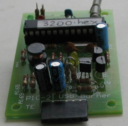
PIC-2 USB BURNER |
|
PICkit-2 set-up software
(4MB) |
This project is a clone of PICkit-2, (the most successful and cheapest
PIC programmer on the market). But PICkit-2 is being phased out and will
not be available in the near future. The replacement is more expensive
and has less features!
PICkit-2 is fully assembled and does not satisfy those who want to
construct their own programmer.
PIC-2 USB Burner is a kit and contains a pre-programmed
PIC18F2550 chip with 3200.hex
All the other components are standard items, except the 1mH choke. This
is supplied as a 10mH choke and you need to remove exactly 340 turns of the winding to
create a 1mH inductor.
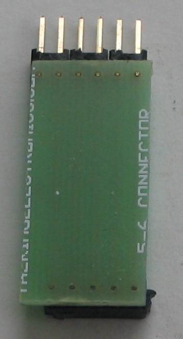
Our kit has two additional features, It comes with a 6 pin to 5 pin
adapter to connect PIC-2 USB Burner to the project you are
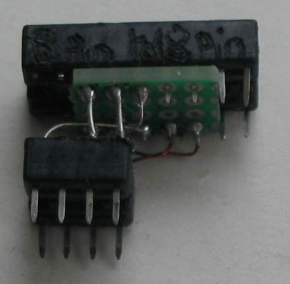
designing and an 8 pin to 18 pin adapter, so you can burn 18 pin chips.
You can also get a "burner board" containing an 8 pin socket (for the
chip you will be programming). See below for all these extras.
To program a PIC chip you need the following:
1. PIC-2 USB Burner and CD titled: "PIC-2 USB Burner software"
2. 6 pin to 5 pin adapter
3. "Burner Board" with 8 pin socket and
4. A project from the list below:
Here are the costs:
PIC-2 USB Burner: $25.00
6 pin to 5 pin adapter: $2.50
8 pin to 18 pin adapter $1.50
"Burner Board" with 8 pin socket: $2.50
CD (700MB) containing software to write your program (NotePad-2), software to convert your program to .hex file (MPASM) and software (titled: PICkit-2 Programmer v2.60) to take the .hex file and burn the PIC chip. This program will appear on your desktop. Plus 180MB of data files, .pdf's, programs and projects as well as a PIC course and electronics course, The CD is titled: "PIC-2 USB Burner software" and costs $10.00
extra PIC12F629 chips $5.00 each
Postage within Australia: $6.50 Overseas: $7.50
Projects using PIC12F629:
Alarm Space Gun uses PIC12F629
Happy Birthday - uses a piezo and PIC12F629 to produce Happy Birthday tune
It's A Small World - uses a piezo and PIC12F629 to produce It's A Small World tune
Lego Chaser - Seven routines on two sets of 10 LEDs - uses a PIC12F629
Lift Counter Uses a PIC12F629 with LED display and up/down buttons.
Music Box Uses PIC12F629 and plays 11 melodies
Sky Writer Uses a PIC12F629 to put messages "in the air."
Whistle Uses a PIC12F629 to detect a whistle - similar to Whistle Key Finder.
2 Digit Counter using a PIC12F629
2 Digit Up/Down Counter 5 different designs. Uses PIC12F629 or PIC16F628 chips.
40 LED Badge - uses a PIC12F629 to show effects on 40 LEDs
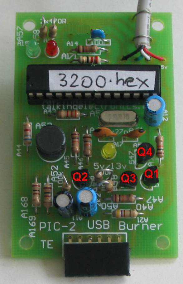
THE CIRCUIT
The
circuit consists of a high-voltage section
plus components to connect the PIC18F2550 chip to the 8-pin programming
socket on the "Burner Board."
The PIC18F2550 is a specially-designed chip that interfaces to the USB
port and handles data from your computer to the chip your are burning, as well as data from
the chip on the "Burner Board" to the computer. This
saves the need for any other chips in the burner project.
The 20MHz crystal must be 20MHz as the chip must handshake, at the
correct speed, with the
program on the computer.
The only other requirement is to generate approx 13.5v to open up a chip,
so it can be read and programmed. Some chips require slightly less than
13v but some need nearly 14v.
This is done via the fourth transistor in the circuit. It receives a waveform from the
PIC18F2550 to turn it ON for a short time then it is turned OFF. This
action delivers a brief pulse of current through the 1mH inductor and
when the transistor is turned off, the inductor produces a high voltage.
This voltage is stored in the 22u electrolytic and appears across a
voltage divider made up of a 6k8 and 3k3. The chip detects the voltage
at the join of the two resistors to maintain a constant 13.5v
This voltage is passed to the chip
being programmed by the first three transistors.
The remaining resistors are safety resistors to prevent the PIC18F2550 being damaged if a short is present on
any of the lines on the "Burner Board."
THE PIC18F2550 CHIP
The
heart of the circuit is a PIC chip. This
chip is pre-programmed in the kit because you need a programmer to
program it! It's a "Catch-22" situation or a "Chicken-and-the-egg.
You need a programmer to program the chip so you can program chips.
This means you cannot build this project yourself from components you
have "on-hand" as you will also need a programmer to load the operating
program into the PIC chip. The kit is not expensive and comes with a
neat PC board. So it's best to get a kit. You can also purchase the 6
pin to 5 pin adapter and a board to hold an 8 pin IC socket as well as
an 8 pin to 18 pin adapter.
This gives you all the tools needed to program 8 pin and 18 pin PIC
chips.
If you have one of our other programmers, you can burn a PIC18F2550 and
build this project.
To program a PIC18F2550 you will need
3200.hex Datasheet for
PIC18F2550

If your USB lead does not have the same colours as shown on the circuit above, use the USB plug shown above to work out the colours. Use a multimeter set to low ohms range and find the +5v wire, the Data- wire, the Data+ wire and the Ground wire. Any copper wire wrapped around the leads is a shield and is not connected to any of our circuitry.
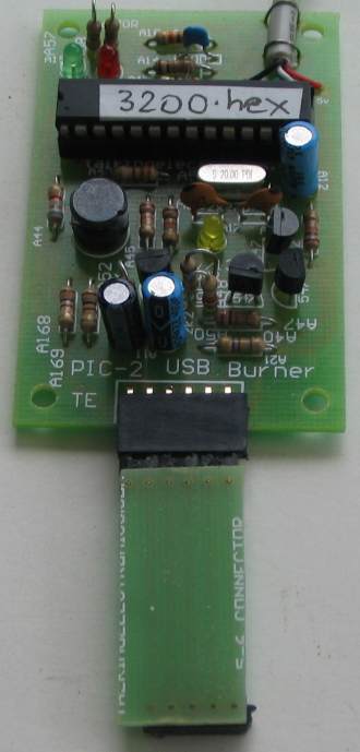
Programmer connected to
project via Adapter
THE INDICATOR LEDs
The project has 3 LEDs. The
green and red LEDs connect to the incoming Data+ and Data- lines of the
USB port and show when signals are present on these lines. These LEDs
show activity and do not have any special importance. They show when
PICkit 2 Programmer software is installed and when your laptop
recognises the PIC-2 USB Burner.
The yellow LED has three features.
It is the high-speed rectifying diode in the voltage-pump section and
allows the positive portions of the high-voltage pulses from the 1mH inductor
to pass to the "accumulator section" where a 22u stores
the high voltage. Two resistors in a voltage-divider network tap this
voltage and send it to a pin on the chip, where the chip controls the pulses sent to the oscillator
transistor. When this voltage is 3.6v the voltage at the top of the
divider is about 13v.
In idle mode, the yellow LED detects 5v and it illuminates at a very low
level.
When the programmer is activated, it "opens-up" the chip you are
programming by supplying 13v to the programming pin and reads the
type-number
of the chip.
The yellow LED will flash very brightly when doing this.
The yellow LED also indicates at high brightness when the programmer is
burning a chip.
1. ASSEMBLING THE KIT
The kit is complete with all
components, a pre-programmed PIC18F2550 chip and USB lead.
All the components fit on the PC board and the IC fits into the 28 pin
IC socket.
You may have to file the edges of the 6 pin socket to make it look neat.
The 1mH choke is made from the 10mH choke provided. Carefully unwind the
winding and leave the last few turns on the core. Now start winding 160
turns then twist the wire twice around the unused pin. With a hot
soldering iron, heat up the wire and pin with a small amount of solder
and this will remove the insulation and connect the wire.
The USB lead is cut to 30cm so the burner can be used close to your
laptop without cluttering the desk with a long lead.
The 4 coloured wires inside the cable must be fitted into the correct
holes.
Fit the chip after all the components are soldered in place and the
project is ready for testing.
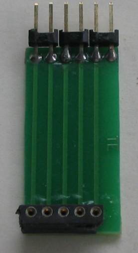
You will need the 6 pin to 5 pin connector.
Make sure you look at the photo before soldering the pins as they are
soldered to the track-side of the board.
If you solder the pins to the wrong side of the board, the connector
will operate in reverse and damage the burner.
Finally you need a board and socket to hold the chip you are going to
"Burn." (program). The following photo shows this board with 5 pins and
wire to the 8-pin socket.
You are now ready to "burn" a chip.
You need to select a kit from the list below. All kits come with a
pre-programmed chip, but with the "Burner" you are able to modify the
program and create different or additional effects.
2. SETTING-UP THE
PIC-2 USB BURNER
The CD that comes with PIC-2
USB Burner contains all the software needed to set up the burner and
program a wide variety of chips.
All the latest chips are recognised by the burner and will program
automatically.
3. IF IT DOESN'T WORK
Both prototypes worked
immediately so the circuit is very reliable. Any faults will be due to
wrong components or a short-circuit between tracks.
The program in the PIC18F2550 (PK2V023200.hex) must match the correct
version of PIC 2 Programmer software (v2.60).
Note: The PIC-2 USB Burner leaves 5v on the
chip after programming and the Burner should be removed so the chip (in
the project you are burning) will reset and execute the program when the
power to the project is turned ON. This only applies
when you are burning a chip "ICSP."
To test the PIC-2 USB Burner,
connect the 6 pin to 5 pin connector, build the Burner Board with 8 pin
socket
and make sure all the wiring has been added
to the board to connect the programming pins to the pins of the chip. Fit a chip that has already been programmed (from one of
the kits) and install PICit-2 v2.60 software on your computer and provide a link to
your desktop. Plug the programmer into one of the USB ports on your
laptop and it will produce a message to show the programmer is
recognised when it is plugged in the first time. (It may not be
identified on some laptops - this does not matter).
Click on PICkit 2 Programmer icon and the programming screen will appear.
At the same time, the software
will send a signal to the Burner to "open up" the chip and read its
part number. Activity on the USB port can be observed via the Data+ and
Data- LEDs flashing slightly and via the yellow LED flashing very
brightly, indicating 13v Vpp is being produced by the "high voltage"
circuit.
If the Data+ and Data- LEDs do not illuminate, the PICkit 2 program on
the laptop has not identified the correct USB port.
This could be due to the PIC-2 USB Burner not sending a recognition
signal to the laptop when first connected.
Disconnect the Burner and re-connect to the computer. Watch the data+
and - LEDs. They
will flash to indicate activity.
If not, the PIC18F2550 chip on the Burner is not being accessed and
sending the initial "handshaking" signal.
Check the yellow LED as it will be dimly lit to indicate 5v.
Remove the 6 pin to 5 pin connector and re-connect it to the Burner socket
or the pins on the "Burner Board."
The yellow LED will flash brightly to indicate it is trying to open up
the chip on the "Burner Board."
If this flash does not occur, the high voltage section is not working.
Make sure the 1mH inductor has continuity as the winding you created may not
be connected to one of the pins.
Make sure the yellow LED is around the correct way and make sure it
still works and has not been damaged during soldering.
Place a LED with 470R on pin 2 to make sure the chip is sending a signal
to the oscillator (buffer) transistor that produces the high voltage.
4.
PROGRAMMING (BURNING)
AN 8 PIN PIC CHIP
The photo shows an 8 pin chip being programmed via the 6pin to 5 pin
connector:
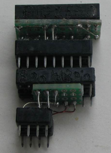
5.
PROGRAMMING (BURNING)
AN 18 PIN PIC CHIP
The burner will also burn 18 pin chips and 28 pin PIC18F2550
chips by using the following two adapters. These are easy to build using
sockets and small pieces of matrix board with tinned copper wires between
the sockets. The 8 pin fits the socket on the boar and this joins an 18
pin socket. The 18 pin socket joins a 20 pin socket and the 28 pin
PIC18F2550 fits into this socket with pin 1 at the end and it overhangs
the socket. Some of the pins in the socket have been removed and this
makes it easy to insert and remove the chip.
PROGRAMMING PROBLEMS ("burning " or "write" problems)
If you have problems burning a chip, here are some helpful notes.
1. Create a new folder and place the following two files in it:
PICkit2v2.61.exe or
PICkit2v2.61.zip
and PK2DeviceFile.dat
If you cannot download an .exe file, download the .zip and extract it
into the folder to produce the .exe file.
2. Create a short-cut to the .exe file and place it on your desktop.
3. Connect the USB programmer to the USB port on your laptop and add the
6 pin to 5 pin connector board. Make sure the board holding the chip
does not have any components connected to the programming pins. The
programmer is very sensitive to any loads on any of the pins and will
not detect the chip.
4.
Click on the PICkit-2 desktop icon and the programming window will
appear and detect the chip you will be programming.
If it does not detect the chip, go to the folder and remove PICKit2.ini
This file is produced at the end of each time you use the programmer and
holds data that is not wanted.
5. If a window appear with Low Vpp, simply click on it to remove it and
click to get the main programming window.
6. Go to Tools and click on "Force PICkit 2" so the 5 volt window
appears on the screen.
QUESTIONS ANSWERED
PICkit 2 can be used as a debugger. We are
not introducing the debugger section as this involves additional
software and an additional "learning curve."
ICD2 and PICkit2 have almost the same capability. PICkit-2 is
cheaper.
PICkit 2 software is designed for MS Windows and a program called “pk2cmd.exe”
is used for Linux based computers. All our discussion is based on
Microsoft Windows computers.
PK2DeviceFile.dat must be in the same folder as PICkit2V2.exe
PK-2 Lite (PICkit2 Lite SE ) is PICkit-2 Student Edition and has fewer
components than
PICkit 2 from Microchip. It is exactly the same
as PIC-2 USB Burner. The Student Edition uses through-hole components
whereas the original design used surface-mount components.
PIC-ICD2 is an In
Circuit Debugger and Programmer. It
is an old design and has many problems. PICit-2 supersedes this device.
MicroChip forums:
http://www.microchip.com/forums/tt.aspx?forumid=15
MPASM is the program that converts the
program you write in TextPad to .hex for PIC-2 USB Burner to download
into the PIC chip.
ICSP - In
Circuit Serial Programming. If a PIC chip is
soldered to the PC board and three programming lines are available (as
well as 5v and 0v), the chip can be re-programmed without removing it.
There can be a problem with this. If a load is connected to any of the
programming pins, the chip may not see full-amplitude signals and will
fail to program.
We suggest removing the chip and burning it on the Burner Board, then
putting it into the project you are working-on.
|
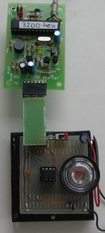
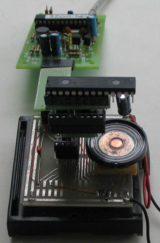
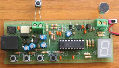
GOING FURTHER This project provides you with a programmer for the whole range of PIC chips, but we have concentrated on two of the smallest chips in the range, the PIC12F629 and PIC16F628 - to keep things simple. No matter if the project is large or small, it has to be designed and the best board to use is a PROTOTYPE BOARD such as the one shown in photo above. All the components and wiring can be seen at the same time. This save turning the board over and making mistakes. Alternatively you can build the project on MATRIX BOARD as shown in the following photo:
This Matrix Board
has been designed by Talking Electronics and contains circular
lands for each hole so the parts can be placed in any hole and
do not have to correspond to grids or conductors under the
board. |
|
|
|
10/2/2013