|
|

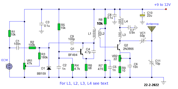
3-TRANSISTOR CIRCUITS
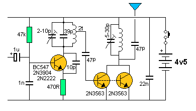
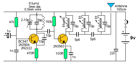
Three transistors will give a wide range of designs. Here are 6 circuits showing how to connect a buffer stage to an oscillator.
But first we need to show the buffer can be connected to the oscillator stage via point A or point B.
Point A has a higher amplitude but since this point is a high-impedance point, any energy taken from this point will affect the amplitude of the oscillator. Point B a low-impedance point, but has a much lower amplitude
Thus we have a decision to make. I prefer the collector take-off point
as it has a larger signal and this signal can be passed to the buffer
stage via a small capacitor to fully drive the buffer transistor.
The capacitor will actually convert a large signal with low current into
a smaller signal with higher current. This is one of amazing things a
capacitor will do.
You may think point A is a low impedance point as it is just a fraction
of an ohm away from the positive rail. But the inductor (coil) is
creating a voltage and waveform at point A and if any load is applied at
this point, the waveform will decrease, because the inductor does not
have much "strength" to produce the waveform. It does not have
much strength because the transistor is being driven very lightly and
the stage is only consuming very little current.
To understand this more clearly, you need to know how the stage works so
you can see how delicate the circuit is.
When the power is applied, the circuit starts to operate due to the 47k
bias resistor on the base.
The next point to note is the base is held rigid by the 1n on the base.
This capacitor has an impedance of less than one ohm at 100MHz and you
can consider the 1n as a 2v battery with an impedance of 1 ohm or a one
ohm resistor sitting on top of a 2v battery. In any case the base is
held very rigid by the 1n.
Now we come to understanding how an NPN transistor "turns on."
It can be turned on in two ways. The emitter can be held rigid and the
base can be raised to 0.6v and if the voltage is raised slightly more
and the base is fed with current, the transistor will conduct and
current will flow in the collector-emitter circuit.
This is the case with the transistor in the audio stage. The emitter is
held rigid and the base is fed with current, once the base is above
0.65v.
The other way to turn on an NPN transistor is to hold the base firm and
lower the emitter. Once the emitter is lower than the base by 0.65v, the
transistor turns on and if the emitter is lowered slightly more, the
transistor turns on more.
This may be difficult to visualise, but this is occurring in the
oscillator stage.
Let's advance a few cycles and see what is happening.
The transistor turns on and the collector pushes the top of the 10p
capacitor towards the emitter.
The energy in the capacitor gets converted to a small voltage and larger
current. We said before, that a capacitor can do this.
The small voltage pushes the emitter lower and this turns ON the
transistor. The result is a little bit of energy is pumped into the capacitor in the tuned
circuit.
At this instant, the coil does not get energy from the transistor
because a coil resists any quick flow of current into it and it acts
like a very large resistor.
The energy in the 10p is now spent and the transistor turns off
slightly. The energy from the capacitor in the tuned circuit passes to the coil and when the
capacitor can no-longer keep the flux in the coil increasing, there
comes a point where the flux starts to collapse. This flux produces a
voltage that is larger than before and is opposite to the previous
voltage.
This is one of the amazing things of a coil and capacitor in parallel.
The voltage at the lower end of the coil-capacitor combination is higher
than the supply and this raises the top plate of the 10p capacitor. This
rises the voltage on the emitter and turns the transistor off
completely.
This allows the tank circuit to produce its amazing HIGH VOLTAGE without
the transistor loading the circuit.
But he coil/capacitor is a very delicate arrangement and it is producing
the high voltage at very low current as it is converting the original
low voltage small current into high voltage very low current.
If we put a load on the circuit at point "A" we will reduce the voltage
and may freeze the circuit.
The following 9 circuits show different ways to "tap-off" the waveform
and amplify it in a stage called a BUFFER.
The BUFFER converts a HIGH IMPEDANCE signal into a LOW
IMPEDANCE signal as the antenna is commonly referred to as a 50
OHM LOAD.
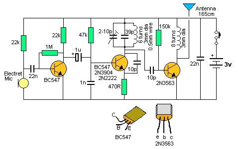
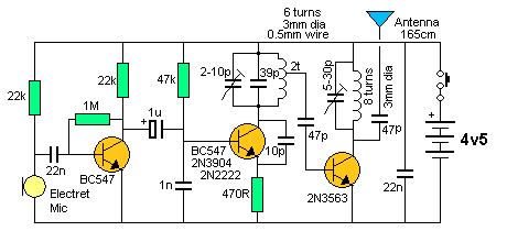
The simplest buffer is shown in the following circuit. It is a common emitter stage with a resistive load.
1. STABILITY
A BC 547 transistor is not very good at amplifying at 100MHz. The circuit above does not give a range greater than the 2-transistor version, but the stability is much greater. The antenna can be touched without the bug drifting off frequency.
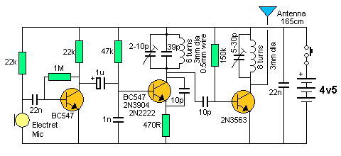
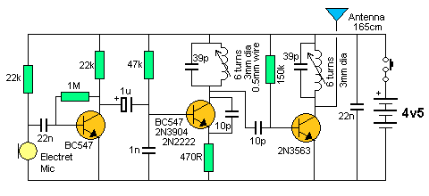
2. INCREASED RANGE
To increase the range,
the output must be increased. This can be done by using an RF transistor
and adding an inductor. This effectively converts more of the current
taken by the circuit into RF output. The output is classified as an
untuned circuit.
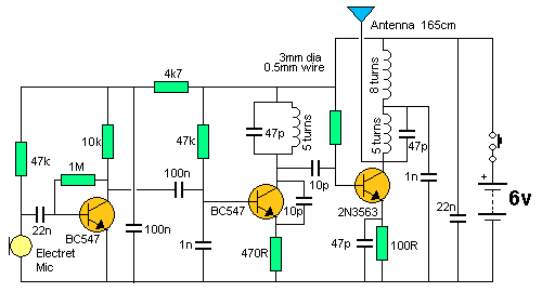
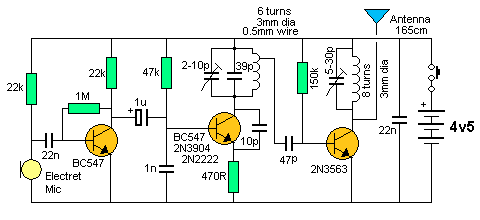
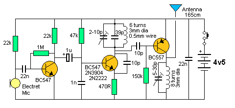
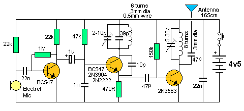
3. MORE RANGE
More output can be obtained by increasing
the voltage and adding a capacitor to the output to tune the buffer
stage. The 5-30p must be adjusted each time the frequency of the bug is
changed. This is best done with a field strength meter. See Talking
Electronics
Field Strength Meter project.
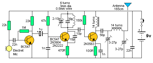
The 2N3563 is capable of passing 15mA in the buffer stage and about 30%
is delivered as RF. This makes the transmitter capable of delivering
about 22mW.
The 2N3563 is also available as PN2563 where PN signifies "plastic
package."
These (this) transistor is not a POWER TRANSISTOR. It is classified as a
SMALL-SIGNAL TRANSISTOR and even though the .pdf
indicates the collector current is 50mA, you will notice all the
specifications are provided at 8mA! That's why we have
allowed a maximum current of 15mA for our calculations.
The 2N3563 (PN3563) is readily available at electronics stockists (Talking Electronics sells them for 90cents for two).
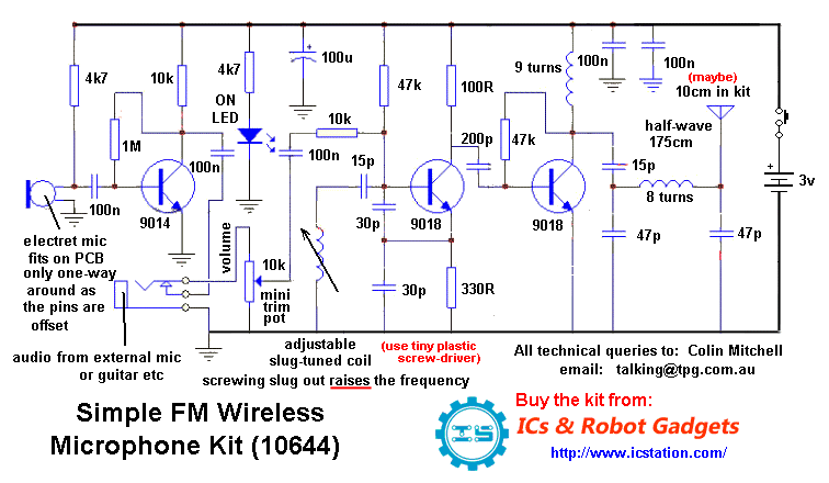
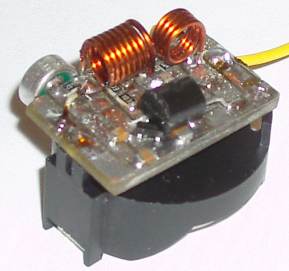
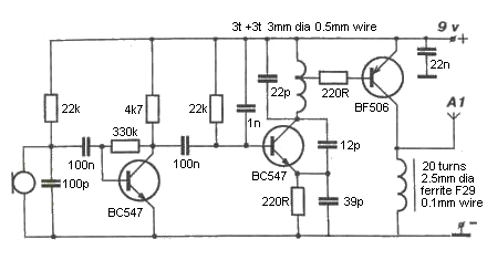
ULTIMA FM BUG - 1km TRANSMITTER
This circuit is available from Talking Electronics as a kit. See the full article HERE.
It has a range of 1km using a 6v supply. The article shows how to peak the project using a LED Power Meter.
Ultima FM Transmitter
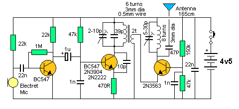
4.
DIFFERENT COUPLINGWe have already mentioned the fact that a capacitor can convert a large waveform with low current into a small waveform with large current.
The following circuit taps off the inductor at a point of low amplitude to put the least load on the tank circuit. The coupling capacitor has been increased to transfer enough energy at low amplitude.
This coupling has exactly the same result as shown in circuit 3.
Circuit 3 is preferred as it is easier to connect to the collector than tap the inductor.
Tapping the oscillator tuned
circuit
A PNP transistor can be used in the buffer stage, but as we said before the BC557 is not as good as an NPN transistor, when operating at high frequencies.
A PNP in the buffer is directly connected
The circuit above shows a PNP transistor
(buffer) connected directly to the oscillator. The buffer is turned ON
during part of the cycle when the oscillator transistor is turning ON
and the voltage developed across the top 3 turns of the coil is greater
than 0.65v.
This design puts a heavy load on the tank circuit and you will see the
previous design has a base resistor to provide this function.
In addition, the 39p emitter bypass capacitor is not needed.
6.
WASTED POWER
The following circuit (from the web) takes
30mA. This is wasted current. As we said before, any voltage above 4.5v
is excess and any current above 12mA for this type of circuit is excess.
A BC 557 cannot deal with any more than 5mA collector-emitter current.
Any more than 5mA is wasted. That's why you need an RF transistor in the
output.
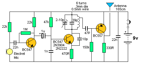
The buffer is taking excess
current
7. EMITTER TAP
The following circuit taps the emitter of
the oscillator stage. We have already explained the collector or the
emitter can be tapped and produce about the same results.
8.
The following circuit uses no biasing on the output transistor. It gets all the energy to activate the base from the oscillator stage.
While this is possible, the amount of energy needed is very large and the oscillator cannot provide enough energy to fully drive the output stage. For the cost of a fraction of a milliamp, it is better to bias the output transistor and get a much-greater output.
Class "C" output
9. ADJUSTABLE OSCILLATOR COIL
To make a circuit more compact or cheaper
(of if you don't have a trimmer), the oscillator coil can be adjusted by
stretching or compressing. When the coil is stretched, the frequency
increases. The buffer circuit has to be adjusted too, to get the
greatest output.
10. POOR DESIGN
Here is a circuit with poor design. It
goes against 6 of the things we have mentioned above.
The first poor design is the low value resistance for the microphone.
For 9v, the microphone load resistor should be 47k. If a low value is
used, the microphone will will over-amplify and create a background noise
similar to bacon and eggs frying.
The 100k separating the
microphone from the base of the audio transistor is not needed. If the microphone is
operated at its correct level of current, this resistor will not be
needed.
The BC 547 is self biased via the 1k and 100k, so the 22k resistor on
the base is not needed.
The 100R on the emitter of the BC338 is a very low value for 9v supply.
The coil is on the PC board has a very low "Q" and the current
taken by the circuit is excessive when the emitter resistor is 100R.
The 22p in series with 2-30p gives a value about 2p to 12p and this is
very small for this tank circuit.
Series capacitors make it very difficult to adjust the frequency as
the trimmer is having a lot of effect on changing the frequency when it
is in series with another capacitor.
The final unusual feature is the 10u and 100u electrolytics. We have
already mentioned that electrolytics do not have any effect with
frequencies around 100MHz. It seems the designer had difficulties with
audio instability, due to the low value of resistance on the microphone
and tried to fix the problem with electrolytics. The circuit has 4
unnecessary components and if you are going into manufacturing, these
will be a costly mistake.
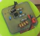
This project is to be avoided if you want a good range with low current
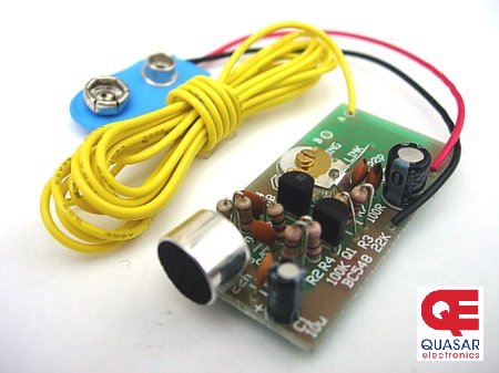
consumption. Some of our other circuits are a better choice. The photo
below shows the assembled circuit.
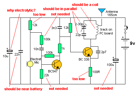
There are actually 10 wrong things. The transistor, capacitor and
coil are too far from each other. This produces a very poor "Q."
design. It was produced by a non-technician. That's why you
have to study electronics, so you don't make a fool of yourself.
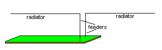
11. MORE POOR DESIGNS
Here is another circuit with extra
complexity and a useless output stage.
Emitter Injection of output
stage
There is no evidence of the above circuit delivering more output than
connecting to the oscillator stage. The circuit uses extra components
and winding the transformer costs more for no extra benefit. The emitter
circuit is very low impedance and the transformer is expected to do a
lot of conversion - called impedance matching. It it trying to match 5k
to 500R.
The output transistor is in common-base configuration and it is usually
used to match impedances or convert the signal from a low impedance
device to a circuit with a high impedance input. This is not the
requirement in our case. We need a circuit to match a high impedance to
a low impedance.
Let's go over the operation of a common-base stage and show how
unsuitable it is in this application.
The emitter is connected to 0v via a 2-turn winding. The base is at
approx 0.65v as it cannot rise higher than the emitter, even though the
two voltage divider resistors are trying to put 1.5v on the base.
And it is held rigid at this voltage via the 1n capacitor, as far as the
100MHz signal is concerned.
When a current flows in the 2-turn winding, a voltage is developed and
suppose this voltage is negative. This will drive the emitter lead below
the 0v line and actually turn the transistor on more.
This will cause more current to flow in the collector circuit and this
current must also flow in the emitter circuit.
This will cause a positive voltage to appear across the 2 turn winding
and counteract the effect we have just produced.
In other words, the stage is working against us and making it very
difficult to deliver energy to the stage.
The output stage is not adding to the power of the project and it is of
no benefit at all. I am surprise it has been presented in electronics
manuals as a good design.
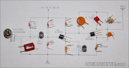
12. ANOTHER POOR DESIGN
This project is very well presented on the web, with large, clear
photos, but the actual design has a number of poor features.
Here is the circuit diagram:
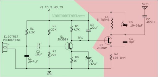
The faults are as follows:
1. The 2k2 resistor to the microphone is too low. It should be at
least 10k for 3v and 47k for 9v.
2. The .047 across the microphone serves no purpose.
3. The 10u coupling the microphone to the first transistor can be much
smaller, 22n to 100n.
4. The direct coupling of the audio stage to RF stage will decrease the
frequency stability.
5. There is no capacitor across the battery.
When you fix these faults you will see how much improvement you get. It
will be considerable.
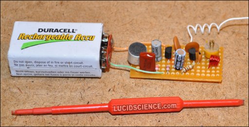
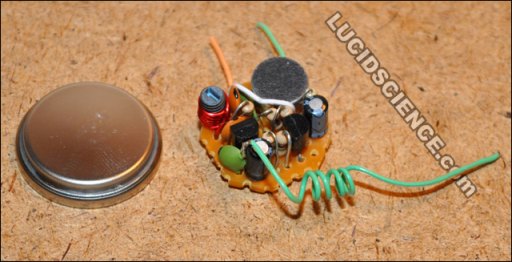
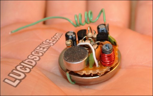
Here are the photos of the completed transmitter and a very small version: