|
|

FAULTS
You can learn a lot about designing a circuit by looking at faulty circuits.
We are now going to look at some badly designed circuits and see what NOT TO DO.
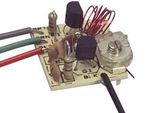
Here is a circuit of a
2-Transistor FM transmitter. It has a number of mistakes in the design.
See Voyager project for a
well-designed circuit. 
The load
resistance for the microphone is too low. It will cause the microphone
to have a very high gain and create a self-oscillating front-end.
The 1u coupling capacitor does not need to be higher than 22n. A ceramic
is quite suitable for this.
The two stages should not be direct coupled. The oscillator stage should
be self-biased so that it creates its own biasing. A "forced bias" does
not allow the transistor to operate in its best set of parameters.
The tapping between the two 27p's gives a very small signal to the
emitter. The 2p2 should tap off the collector. The parallel 27p's gives
a value of 13p, whereas the capacitance across the inductor should be
about 47p for the best "Q" for the tank circuit. No value has been given
for L1. It should be 5 turns 0.25mm wire 3mm dia.
The 47u across the battery is not needed. It should be replaced with 22n
to tighten up the rails for the 100MHz oscillator.
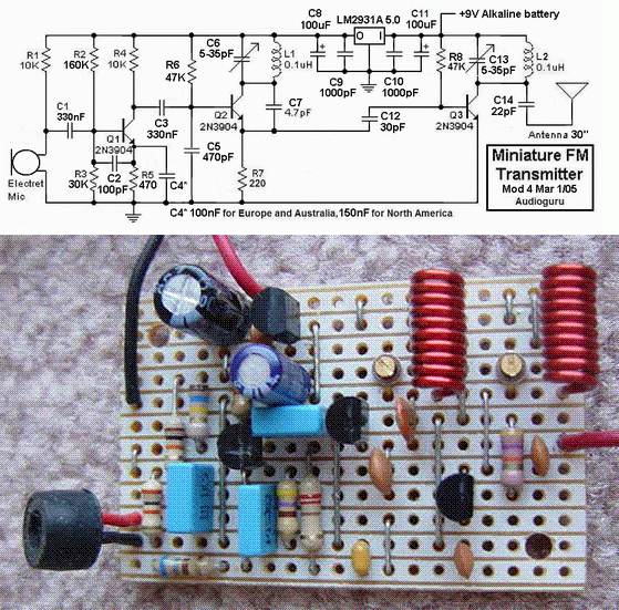
Next we have
an FM transmitter that looks to be well-designed. Apart from the complex
circuit, there are a number of fundamentally incorrect features that
make the circuit unreliable.
And the layout is one of the worst I have seen for an FM transmitter.
This type of circuit should NEVER be laid out on strip-board or any
type of board that has extra conductive lines as they create "wires"
that radiate signal and they can be so effective that all the signal is
radiated and none is retained to keep the oscillator in a state of
oscillation. That's why this type of layout can result in
non-operation.
The first item we will look at is the "Q" of the tank circuit.
This is a factor known as "Quality" and comes from the fact that an
inductor will produce a voltage (of opposite polarity) that can be many
times higher than the voltage applied to it.
And that's what a circuit like this FM transmitter does. The voltage
produced by the capacitor and parallel inductor on the collector, will
produce a voltage in this case that will be about twice the rail
voltage.
These two components are called a TANK CIRCUIT and to get them to
produce this voltage, the energy stored (and released) by the
capacitor must be equal to that of the inductor. The two work like
tipping water from one jug to another of the same size and back again.
If one jug is smaller, we only get the energy from the smaller jug.
In this case the 5-35p air trimmer will be set at about 20p for 90MHz
while the energy stored in the 10 turn coil will be twice that needed.
The 10 turn coil should be reduced to 5 turns and the capacitor should
be increased to 39p - 47p. This will give the circuit a higher resultant
output voltage.
With a low Q, the energy through C7 (4p7) will be very small.
We don't know how or where the tracks are cut on the "strip-board" but
you can see some of the tracks will connect to the end of the 4p7 that
goes to the emitter.
This track acts like a "transmission line" and since it is very wide, it
will have a high value of radiation.
This means a certain amount of the energy delivered by the 4p7 will be
lost to the surroundings and any handling of the project will cause
drifting or it could come to a point where the oscillator fails when
handled.
In addition, some of the energy delivered by the 4p7 is being lost via
the 30p coupling capacitor and the circuit may fail to work. We found
10p is needed.
The circuit may be successful as the oscillator transistor is being
heavily driven via the 220R in the emitter. This may overcome the
short-falls in the other design-concepts, but the 30p "take-off" should
be connected to the collector of the oscillator stage as it will
transfer a lot more energy.
High frequency circuits like this need to be designed so the power rails
are "tight." This not only means electrical and electronic "tightness"
but also physical tightness.
The 1n across the power rails for the oscillator is insufficient to give
good tightness (it should be 22n) and the placement of the components on
the board is far too spread-out.
This makes the project very susceptible to handling and drifting.
Since the output transistor is a buffer, the 22p on the antenna is not
needed and simply reduces the range.
The 10k resistor for the electret mic is too low for our high-sensitivity
microphones. It should be 47k for 5v rail.
The 100u electrolytic across the battery is totally unnecessary as the
current consumption is only a few milliamp. In addition, the 100u on the
output of the regulator needs to be only 1u to 10u.
Overall, I consider the circuit is taking 2 - 3 times more current than
it needs.
Our 9v Voyager circuit consumes 7-10mA for 800metre range. This circuit
will consumes more than 25mA.
One final point. The air trimmer should be in parallel with a capacitor
(39p) so the trimmer is only adjusting a small amount of the total
capacitance. This makes it easier to tune across the band and set the
frequency.
Here is a circuit from CircuitsToday:
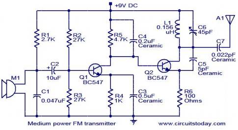
It's
a circuit that looks to be ok.
But you have to go deeper into the designed to see the faults.
The Microphone symbol shows the old-fashioned mic for a telephone.
It should be an electret mic symbol:
![]()
The 47n across the microphone is not needed if the mic is biased correctly.
The 10u coupling to the base of the first transistor can be 22n.
The oscillator should be self-biased. This allows it to operate freely and maintain better stability.
The 100R in the emitter should be 560R as the BC547 can only handle a very low current at high frequency.
The inductor should be specified as 5 turns of 0.5mm wire 3.5mm dia coil. The supply should be "decoupled" via a 22n capacitor.
The 200n capacitor on the base of the oscillator transistor is too high. It should be 1n.
The 22n on the antenna is not needed.
Here's an FM transmitter with a number of mistakes.
It was designed by Harry Lythall of Sweden and I am surprised at the number of mistakes.
1. You don't need 10u and
100u electrolytics. You don't need any electrolytics AT ALL.
2. The microphone is heavily turned on via the 12k resistor then its
output is attenuated by the 100k resistor. 12k is too low and will
overload the microphone considerably.
3. The oscillator is DC biased via the first transistor and this is not
a good arrangement. The oscillator should be "self biased."
4. The trimmer capacitor should be in parallel with the 22p so that it
has a small effect on adjusting the frequency.
5. R5 will have almost no effect on the operation of the circuit and is
not needed.
6. BC338 is a power transistor and is not designed for 100MHz
operation.
7. The 22n should be across the battery (and not at the audio end of the
circuit) because the function of the 22n is to keep the power rails
"tight" at the oscillator end.
8. The coil is etched on the PC board and this type of coil has a very
low "Q." The circuit will have a very low output.
Overall the circuit is a very poor design and is not worth building.
A number of major faults
with this circuit.
1. The 4k7 feeding the electret microphone is too low. It should be 47k
to prevent overloading the microphone.
2. The coil on the PC board has a very low "Q" and will produce a very
low output.
3. The 12p across the coil is too low. It should be 33p to 47p and the
coil should be changed to 6 turns 3mm dia enamelled wire so the two
components have the correct L-C ratio.
4. There is no way to adjust the frequency of transmission.
5. The coupling capacitor to the final transistor is too high. It should
be 47p maximum.
6. A BC557 transistor is not a good RF amplifier.
![]()
![]()
TELEPHONE BUG
Look at the coil. A floppy coil like this is totally unsuitable as it will be "telephonic." This means it will vibrate when bumped and will even pick up sounds such as talking, music and footsteps and transmit them just like a microphone. I suggest you build this circuit and use 7 turns of thin wire on an 8-10mm pen and see how the coil picks up every sound in the room. Simply connect a 9v supply and the circuit will work. The coil should be 6t and 3mm diameter, using 0.5mm enamelled wire.
 |
 |
|
|
|
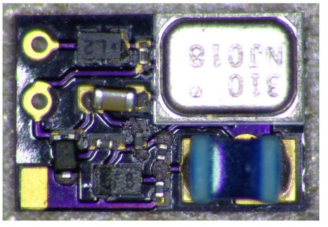
TINY BUG
This circuit is very small but it does not have the arrangement of
components that you would normally expect. The output transistor does
not have a connection to the positive rail and the base does not have a
bias resistor. Build it and see how much range you get.
Here is the data sheet for the microphone.
This 3-transistor circuit has many faults.
The 100n on the output of the microphone does nothing. It can be
removed.
There is no reason to reduce the gain of the first stage to 22 when a
volume control is on the input. The 100R can be removed.
The 30p across the 5.5 turn coil forms a tuned circuit and only does
anything at a particular frequency.
The capacitor does nothing at the wrong frequency. It can be removed.
The inductor on the antenna does nothing in this case and can be removed.
The 100R on the output transistor reduces the output considerably.
Here is a 2-tranaiator circuit that has been copied from our website:
The inductance of the coil is larger than it should be. The coil is 10
turns, 6.5mm diameter and spaced to a length of 15mm. This produces a
value of 0.2uH and you may have to turn the air trimmer to a very small
value to received the stations.
This produces a very poor resonance value and the output will be very
small.
That's why some of the readers on the youtube.com website, said they got
a very short range.
Try 5 turns, 6.5mm spacing and keep the turns close together.
18/6/2019