|
|
|
|

This project will save you burning your food.
It will remind you to re-call a customer
and it will tell you when a TV program is about to start.
These are the sort of
things the timer can be used for.
Just turn the dials to the required time and turn the project ON.
When the dials are turned to "0" "0" the LED
will flash but the timer will not beep.
This project replaces an electronic timer bought some 15 years ago. It used
a CD4541 chip with 24 timing resistors on two 12 position rotary switches
and numerous other components to produce the beep.
But the electros went leaky and 20 minutes extended to 35 and 1 hour on
the timer
never produced a beep.
So this timer was born.
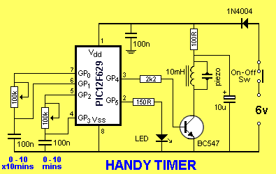
The timing is determined by the oscillator in the micro
and this is fairly accurate and reliable over a wide temperature range.
It is certainly better than external timing capacitors.
The only problem with the project is detecting the position of the wiper
on the two pots.
The ability to detect 10 locations on a pot is governed by the
accuracy of the 100n capacitor and the value of the pot.
The capacitors in our prototype had a 5%-10% accuracy but the pot had a 20% accuracy.
Some 100k pots were 80k and others 91k.
When this is combined, we get a wide variation.
That's why we had to allow for an adjustment.
We have specially made the timing so that you need to add a value across
the 100n capacitors to get 9 beeps when the pots are turned to 9
0'clock. Extra 10n and 47n capacitors are included in the kit. You can
connect two 47n in series to get an added 23n or put 10n across a 100n.
One of our pots was 81k and the 100n was 102n. This needed 2 x 47n in series
across the 100n.
The other was 91k and 107n and needed 10n in parallel across the 100n.
It is very difficult lowering the 100n so this is the best option.
Once the pot corresponds to the numbers on a clock, the rest of the
timing is done by the chip and uses a 1 minute routine that is called
a number of times.
The LED is illuminated for a very short period of time during approx
each second and this is done within the 1 minute routine. The frequency of 3860Hz for
the piezo was determined by using our Square Wave Oscillator project and
turning the pot until the output was the highest. The frequency was then detected
on a frequency meter and used in this project to get
the best output.
The 10mH choke increases the output considerably as it provides the
piezo with a very high waveform. The piezo is actually a 22n capacitor
and when combined with the 10mH inductor, the two work as a resonant
circuit to produce the high waveform.
The 100R, and 10u electrolytic across the piezo section of the circuit,
prevent spikes and dips in the supply caused by the low impedance of the
10mH choke from upsetting the micro.
The project takes approx 2mA during operation but considerably more
during the beep.
|
INSTRUCTIONS FOR
USE The first dial indicates the number of "minutes x10" and the numbers 10, 20, 30, 40 - - - - 90 are in the same locations as on the face of a clock. The second dial indicates the number of "minutes x1" with the numbers 1, 2, 3, 4, 5 . . .8, 9 in the same places as the numbers on a clock. Turn the first dial to the number of minutes x10 and you can add extra minutes by turning the second dial. Turn the dials and then turn the project ON. You will see the LED flash then produce beeps according to the number of "x10 minutes" detected by the circuit. If you have only selected the number of minutes x1 the beeps will let you know the number detected by the circuit. The LED will continue to flash approx every second to show the timer is working and the piezo will beep when the time has expired. If the timer squeals, the battery is flat. |
CONSTRUCTION
GOING
FURTHER
Handy Timer
13/10/10
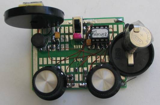
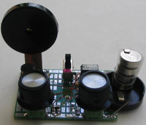
You can build the circuit on any
type of Proto board. We have chosen our surface-mount board as it makes
a neat project and you can see all the wiring at the same time.
Use 4 button cells in a holder as the circuit requires very little
current and they will last a long time.
The
PROGRAM
This project is part of a course in PIC Programming. See left
index on Talking Electronics website: List of PIC
Projects: for the projects in this course.
The course consists of
building these projects and modifying the programs to learn the art of
programming PIC microcontrollers.
Most of the projects are very simple however they cover many different
routines and enable you to build up your knowledge.
This project has been produced on our standard template and contains a
number of sub-routines taken from other projects.
The hardest part of any program is interfacing it with the outside
world. One of these problems is to get accurate positioning of the pots.
To do this we
produced a sub-routine that created a value from a loop counter. We then adjusted the interval between each "look
to see when the 100n was charged" and when the loop counter was 10 for
the 10 o'clock position, it was complete.
The 1 minute delay could be determined mathematically by counting the
microseconds in the program but it was much easier to use a stop watch.
Finally, the LED was turned on for only 5mS per 800mS in the 1 minute
delay. This is less than 1% but the flash appears to be a lot longer due
to the Persistence of Vision of the eye.
The program contains a number a new subroutine that you
will be able to "cut and paste" for projects in the future.
If you want to modify the program you will need a programmer, a board to
hold the 8 pin chip during programming and an adapter to connect between
the programmer and PC board.
These are
covered in our article "Pick-A-PIC."
Here are the files you will need for "burning" your chip and/or
modifying the program:
Timer.asm
Timer.txt
Timer.hex
The following program is for viewing. It may contain
spaces or hidden characters that will not compile correctly to produce a
.hex file. Use the .hex file above to burn your chip or the .asm file to
modify the program.
;*******************************
;Handy Timer.asm
;13-10-2010
;*******************************
	list	p=12F629
	radix	dec
	include	"p12f629.inc"

	errorlevel -302	; Don't complain about BANK 1 Registers

	__CONFIG	_MCLRE_OFF & _CP_OFF
		& _WDT_OFF & _INTRC_OSC_NOCLKOUT  ;Internal osc.

;_MCLRE_OFF  - master clear must be off for gp3 to be input pin

;****************************************************************
; variables - names and files
;****************************************************************


temp1		equ 20h	;
temp2		equ 21h	;
temp3		equ 22h	;
temp4		equ 23h	;
_beepA		equ 24h	;for beep tone
_beepB		equ 25h	;for beep tone
_flash		equ 26h ;for flashing the LED
_potA		equ 27h ;holds value 1-10 for x10minutes
_potB		equ 28h ;holds value 1-10 for minutes
_loops		equ 29h ;
temp		equ 2Ah ;
del_x		equ 2Bh ;
del_y		equ 2Ch ;
xmin_1		equ 2Dh ;
xmin_2		equ 2Eh ;
xmin_3		equ 2Fh ;
temp_10		equ 30h


;****************************************************************
;Equates
;****************************************************************
status	equ	0x03
rp1	equ	0x06
rp0	equ	0x05
GPIO 	equ 0x05


status	equ	03h
option_reg  equ 81h


		; bits on GPIO

pin7	equ	0	;GP0  out for x10mins
pin6	equ	1	;GP1  in for x10mins
pin5	equ	2	;GP2  out for mins
pin4	equ	3	;GP3  in for mins
pin3	equ	4	;GP4  piezo
pin2	equ	5	;GP5  LED


	;bits

rp0	equ	5	;bit 5 of the status register

;****************************************************************
;Beginning of program
;****************************************************************
	org	0x00
	nop
	nop
	nop
	nop
	nop
SetUp	bsf	status, rp0 	;Bank 1
       	movlw	b'11001010' ;Set TRIS  GP0,2,4,5 out GP1,3,input
	movwf	TRISIO	   	    ;
	bcf	status, rp0	;bank 0
	movlw   07h         	;turn off Comparator ports
        movwf   CMCON       	;must be placed in bank 0
        call	flash
	clrf 	GPIO       	;Clear GPIO of junk
	goto 	Main


;****************************************************************
;* Sub Routines and delays			*
;****************************************************************


	;approx 150uS delay for loops for potA and PotB

_150uS	movlw	.67
	movwf	temp1
_150u	nop
	decfsz 	temp1,f
	goto 	_150u
	retlw 	00


_20mS	movlw	.20
	movwf	temp2
_20	nop
	decfsz 	temp1,f
	goto 	_20
	decfsz 	temp2,f
	goto 	_20
	retlw 	00

_500mS	movlw	0FFh
	movwf	temp2
_500	goto	$+1
	goto	$+1
	decfsz 	temp1,f
	goto 	_500
	decfsz 	temp2,f
	goto 	_500
	retlw 	00


_x1beep	movlw	80h
	movwf	del_y
	movlw	.45
	movwf	del_x
	nop
	decfsz	del_x,1
	goto	$-2
	movlw	b'00010000'
	xorwf	gpio,1		;toggle GP4
	decfsz	del_y,1
	goto	$-8
	call	_500mS
	call	_500mS
	retlw	00

beep	movlw	0ffh
	movwf	del_y
	movlw	.45
	movwf	del_x
	nop
	decfsz	del_x,1
	goto	$-2
	movlw	b'00010000'
	xorwf	gpio,1		;toggle GP4
	decfsz	del_y,1
	goto	$-8
	call	_500mS
	call	_500mS
	retlw	00

longbeep
	movlw	0ffh
	movwf	del_y
	movlw	0ffh
	movwf	del_x
	nop
	decfsz	del_x,1
	goto	$-2
	movlw	b'00010000'
	xorwf	gpio,1		;toggle GP4
	decfsz	del_y,1
	goto	$-8
	call	_500mS
	retlw	00


	;flash LED at start-up

flash	movlw	0ffh
	movwf	_flash
	bsf		gpio,5
	nop
	decfsz	_flash,1
	goto	$-2
	bcf		gpio,5
	retlw	00


	;potA = x10minutes
	;Detects position of potA
	; _potA will have 0-9


potA	clrf	_potA
	clrf	temp
	bcf	gpio,0	;to discharge 100n
	call	_20mS
	call	_20mS
	bsf	gpio,0	;to charge 100n
	call	_150uS
	btfsc	gpio,1
	retlw	00	;_potA & temp exits with 0-9
	incf	_potA,1
	incf	temp,1
	goto	$-5


potB	clrf	_potB
	clrf	temp
	bcf	gpio,2	;to discharge 100n
	call	_20mS
	call	_20mS
	bsf	gpio,2	;to charge 100n
	call	_150uS
	btfsc	gpio,3
	retlw	00	;_potB & temp exits with 0-9
	incf	_potB,3
	incf	temp,1
	goto	$-5

	;x1min  - 1 minute delay

x1min	movlw	.78
	movwf	xmin_3
_1min	goto	$+1
	goto	$+1
	goto	$+1
	goto	$+1
	decfsz 	xmin_1,f
	goto 	_1min
	decfsz 	xmin_2,f
	goto	$+2
	goto	$+3
	bcf	gpio,5	;give the LED illumination-time
	goto 	_1min
	decfsz 	xmin_3,f
	goto	$+2
	retlw 	00
	bsf		gpio,5	;flash LED
	goto	$+1
	goto	$+1
	goto	$+1
	goto	$+1
	goto 	_1min

x10mins	movlw	.10
	movwf	temp_10
	call	x1min
	decfsz	temp_10,1
	goto	$-2
	retlw	00

;****************************************************************
;* Main 							*
;****************************************************************

Main	call	potA	;returns with value in _potA and temp
	movlw 	00h
	xorwf	temp,0
	btfsc	status,2	;temp=00=zero "x10minutes"
	goto	min_only
	call	longbeep	;long beep to indicate x10minutes
	decfsz	temp,1
	goto	$-2
			;temp destroyed
			;only _potA 1-9 will be used
	call	x10mins
	decfsz	_potA,1
	goto	$-2


	;check for x1min set on potB

	call	potB
	movlw 	00h
	xorwf	temp,0
	btfsc	status,2	;temp=00=zero minutes
	goto	$+4		; no setting on pot
	call	x1min
	decfsz	_potB,1
	goto	$-2
	call	beep
	goto	$-1


min_only
	call	potB
	movlw 	00h
	xorwf	temp,0
	btfsc	status,2	;temp=00=zero "x10minutes"
	goto	Main	    ; no sound as no setting on pots
	call	_x1beep 	;x1_beep to indicate x1minutes
	decfsz	temp,1
	goto	$-2
		;temp destroyed
		;only _potB 1-9 will be used
	call	x1min
	decfsz	_potB,1
	goto	$-2
	call	beep
	goto	$-1


	END
You can add additional features to this
project by writing your own program or modifying the program above. Send any additions to Talking
Electronics for inclusion in this article.
Parts List
Cost:
au$20.00
plus postage
Kits
are available
1 -
150R SM
resistor
1 -
100R SM
resistor
1 -
2k2 SM
resistor
2 - 100k pots
3 - 100n SM capacitors
2 - 10n SM capacitors
(for adjusting 100n)
2 - 47n SM capacitors
(for adjusting 100n)
1 - 10u SM electrolytic
1 - SM red LED
1 - SM diode
1 - BC847 SM transistor
1 - SPDT mini slide switch
1 - 10mH choke
1 - piezo diaphragm
1 - 8 pin IC socket
2 - knobs for pots
20cm fine enamelled wire
20cm - very fine solder
1 - PIC12F629 chip (with
Timer routine)
1 - battery holder
4 -
button cells
1 - 3cm x 1cm blank PCB for piezo
1 - piece double-sided tape
1 - Prototype PC board