|
Pick A PIC Project |
|
|
If you want to get
into the next generation of "project-design," you need to look into the
magic world of a MICRO. a USB port:
A micro can simplify your project, reduce its size,
increase its capability and reduce the cost.
But best of all, it can be centered around a software program that can
be hidden from prying eye and this will make your project unable to be
copied.
Talking
Electronics has produced a range of projects using a MICRO
and this article will get you into designing your own project at the
lowest cost.
There are a number of microcontrollers
on the market and various paths you can follow to produce a
microcontroller project - at least 3 different manufacturers and more than 3 paths
are available.
Ours is just one of these options and in our opinion it is the
cheapest and simplest way to get into microcontroller programming.
We have chosen the PIC micro, by MicroChip as it has a huge following on
the web with a large range of projects and support groups.
In addition we have chosen hand-programming using a template to get you
started. Our method produces lines of code where each
line is an instruction. This is the simplest way a PIC program is produced
and you produce it by
hand.
The instructions are fairly easy to understand as they
consist of the first letter of words of a sentence, such as btfss (bit test file
and skip if set) and these are called
mnemonics.
There are only (about) 35 instructions and these cover the entire capability of
the microcontroller.
This is the simplest and easiest way to write a program and is aligned
to the early days of programming where it was called "Machine Code."
This is the "Lowest Level Language" as the instructions are
directly understood by the micro. Any other language is a "higher level
language" as each instruction is usually more powerful but much
harder to add to the program. You need to learn these languages and how to
write them in a program
(how to structure each line) as they use symbols such as: "{, }, [, ], <<, >>"
to produce code such as:
void waitsync(void)
{
re: while (RX)
{
};
TMR0=0;
if(errorbyte > MAXERR) { errmark=1; return;};
Our approach avoids a lot
of complexity and frustration. It only involves 35 instructions.
We have made programming even easier by providing a number of complete
projects as well as "sub-routines"
that can be copied and pasted into your program.
On top of this we have provided a LIBRARY OF TERMS to help you
understand all the terms. And to simplify things we have concentrated on two PIC chips. An 8 pin and an 18 pin chip.
The 8 pin chip can be either PIC12F629 or PIC12F675 and the 18 pin chip
is PIC16F628 or PIC16F675.
Even though these chips are the simplest in the range, do not
under-estimate their capability.
The PIC16F628 can
easily replace 20 individual logic chips and produce a project with
amazing capability. We have produced a Tic Tac Toe game that
always wins (or draws) and a Dialing Alarm-2
that produces DTMF tones, a Hee Haw sound and a feature that opens up a
microphone to let you listen to the target zone.
By using our suggestions, you can use the chip
to its fullest and create a more-complex program than any other method. You
don't have to learn any other "language" or get involved with any
"developmental tools" (some of these are very frustrating to use).
We have also used very simple "programming techniques" in that our
"lines of code" are very easy to follow and clearly explained. Some
developers use "very clever" instructions that take "hours to
understand" and this leaves you in a state of frustration. We do it "the
simple way" and you feel bolstered after every project you complete.
Of course you cannot produce an "all talking, all dancing"
project with these tiny micros but our aim is to
get you started.
If you can visualise the capabilities of a 5 chip project; multiply
this by 10 and you have the possibilities of what you are about to
encounter. This may seem surprising but as your program gets larger, you
can use some of your pre-written sub-routines and this makes it more-powerful
and the last-few lines of code can achieve enormous capabilities.
Producing a microcontroller design is often cheaper than using lots of
discrete chips; plus the board is smaller. But most important, the program
can be "locked away" from prying eyes and can be marketed.
Now is the time to think of some ideas. In most cases they will be
"do-able." And we will show you the way.
Below is a list of projects we have developed for the two chips as well as PIC
Programmer MkV, for those with a desk-top computer or tower and
PICkit-2 Burner for those with a lap-top computer.
First you have to decide on the programmer. It will depend on the "port"
you have on your computer.
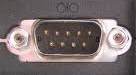
Look at your
computer or "tower" or lap-top. Does it have a serial port:
You need to buy
PIC Programmer MkV kit
You need to buy
PICkit-2 Burner kit.
Once you have decided on a programmer,
you will need to buy the kit and assemble it.
Connect it to your
computer and go to the projects below.
Start with:
World's Simplest Program.
It uses a PIC12F629 and has only
4 instructions to blink a LED. It shows how the Watch-Dog Timer resets
the chip every 150mS. It's not a normal type
of program but it tests the micro, the programmer and the circuit you
have constructed.
Then alter one or
two of the instructions and see what happens. If you can do this, you are ready to start.
The projects are divided into two groups: PIC12F629 (8 pin) or PIC16F628 (18
pin).
Both micros use the same instruction-set (only some small differences)
and both are identical when it comes to learning how they operate. The
only difference is the 8 pin micro has 5 in/out lines and 1 input-only
line. The 18 pin micro has 15 outputs (plus one input-only line).
WE START AT "GROUND ZERO"
The following list of data sheets, projects and "help" articles
is like a course. It covers everything you need to know about producing
a PIC microcontroller project.
Everything can be accessed via links on
Talking Electronics website (http://www.talkingelectronics.com) and is also available on CD from Talking Electronics for $10.00
posted to anywhere in the world.
This is the lowest-cost course ANYWHERE on the web and it starts
at less than $50.00 for a PIC programmer and project. You also get a
CD containing all the necessary information including instructions for
all the kits.
Even though our approach is the simplest way to get into PIC
programming, you may have a question and it
can be answered by contacting Colin
Mitchell or going to a forum, where microcontroller questions will
be answered 24 hours a day! One of the forums is: http://www.electro-tech-online.com/
USING OTHER MICROS
There are
a number of other micros on the market and many of them offer a similar
range, price and set of features as the PIC.
We have chosen the PIC because of the enormous amount of help and number
of projects on the web.
At this point in time, no-one has written an article to say any other
processor is markedly better than a PIC and so you are not being steered
down a "dead end."
One of the other manufacturers ceased to produce their smallest micro
and that's why their "attiny" range was not chosen. We were just
about to promote the attiny12 series when it ceased to be manufactured.
Luckily, the equivalent PIC chip is cheaper.
START
A set of experiments using the LED Fx PC board. The course contains a folder with the file for writing your program (NotePad2), converting your .asm to .hex (MPASM) and for burning a PIC micro (ICPROG).
You will need a fully built LED Fx, and Pic Programmer MkV
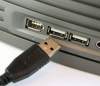
If you have a USB port, you will need PIC-2 USB Burner and PICkit2 software.
Here are the data sheets, projects and "help" articles:
PINOUTS
Blank template for PIC12F629 or
select a PIC12F629 project and remove unwanted code. READ THE INSTRUCTIONS
P2(100
Helpful Hints)
P3 The XOR Trick
12/10/2010
Blank template for PIC16F628 or
select a PIC16F628 project and remove unwanted code.
To work on (or produce) a template you will need:
Notepad2.zip or
Notepad2.exe
Data sheet for PIC12F629
(5MB .pdf)
Data sheet for PIC16F628 (2.6MB .pdf)
Library of terms A-E
Library of terms E-P
Library of terms P-Z
List of Instructions for
PIC12F629 then go to:
Explaining the
Instructions &
more details
List of Instructions for
PIC16F628 then go to:
Explaining the
Instructions &
more details
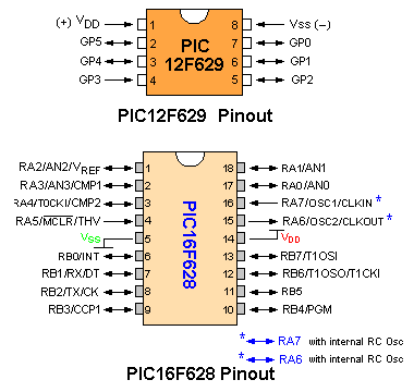
PIC12F629 Pinout
PIC16F628 Pinout
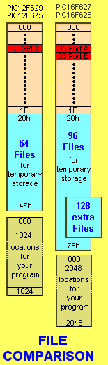
Files in PIC12F629 and PIC16F628
Software for PIC Programmer MkV -
Icprog105c
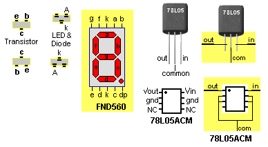
Surface Mount Pin-outs
The XOR Trick - learning about the power
of the XOR function
2 Things
at Once - tutorial - using interrupt and isr to do 2 things at the
same time.
100 Helpful Hints - things you
need to know, to be able to produce a program
PROJECTS:
Pic Programmer MkV
Simple PIC programmer - uses just 12
Parts - for serial port
PIC-2 USB Burner for lap-top USB port
World's
Simplest Program for a PIC12F629. It uses only 8 instructions and
blinks a LED. It shows how the Watch-Dog Timer resets the chip every
18mS to 2400mS if not cleared.
Kit contains PC board, 6 pin to 5 pin adapter, 8pin socket, chip,
LED, resistor and pins to create a development board for burning 8 pin
PIC chips.
PIC12F629:
Alarm Space Gun uses
PIC12F629
Capacitance Meter -
measure capacitor values from 1p to 100u
Crossing Sound -
for your model railway layout
EEPROM Speed - write
and read EEPROM to see how fast it gets done.
Happy Birthday - uses
a piezo and PIC12F629 to produce Happy Birthday tune
It's A Small World - uses a
piezo and PIC12F629 to produce It's A Small World tune
Joy Stick
Controller
- control 2 servo's via a Joy Stick
Lego Chaser - Seven
routines on two sets of 10 LEDs - uses a PIC12F629
LED Fx - 12 different effects on
a set of 3 ultra bright white LEDs.
Lift Counter
Uses a PIC12F629 with LED display and up/down buttons.
Music Box Uses
PIC12F629 and plays 11 melodies
Sky Writer Uses
a PIC12F629
to put messages "in the air."
Servo
Motor Controller - control 2 servo's via a Joy Stick
Solar Tracker-1
Uses a PIC12F629 with H-bridge to allow a solar panel to track the sun.
Touch Switch - use a
PIC to create on/off via a touch pad
Whistle Uses a
PIC12F629 to detect a whistle - similar to Whistle Key Finder.
2 Digit Counter using a PIC12F629
2 Digit
Up/Down Counter 5 different designs. Uses PIC12F629 or PIC16F628 chips.
12 Digit Running
Sign - uses a 12 digit calculator display to produce running
messages
40 LED Badge -
uses a PIC12F629 to show effects on 40 LEDs
PIC12F675:
Audio CRO
uses PIC12F675 to
produce a simple audio CRO via a spinning PCB on the shaft of a motor. A
good mechanical as well as electronic project.
PIC16F628:
Dial Alarm-2
Dials 2 phone numbers via DTMF and produces a Hee Haw Sound. Has a
in-built microphone to listen to the target zone. Uses a PIC16F628
PIC Lick-1 A
development board for the PIC16F628
Simon 4 buttons are used to repeat a
sequence of Lights and sounds. Uses a PIC16F628
Stroop Game A very
interesting Psychological game named after the doctor who introduced the
test. Uses a PIC16F628
Tic Tac Toe A
challenging game where the computer wins or draws. Uses a PIC16F628.
15x7 Display using a PIC16F628
2 Digit
Up/Down Counter 5 different designs. Uses PIC12F629 or PIC16F628 chips.
12 Digit Display A
12 Digit calculator display is used to produce a running sign and other
effects. Uses a PIC16F628
HELPFUL FACTS
Here is some helpful facts on the PIC12F629 and PIC16F628 micros:
The PIC12F629 has 1024 locations for your program. This is 4 pages and
is commonly called 1k of memory. A page has 256 locations (0FFh
locations). Page0 consists of locations 00h to 0FFh. Page1 consists of
locations 100h to 1FFh. Page2 consists of locations 200h to 2FFh. Page3
300h to 3FFh.
The PIC16F628 has 2048 locations for your program. This is 8 pages. This
is 2k of memory for your program.
Goto and Call instructions access the whole of memory.
A table can only be 0FFh locations long and it must not go over a
border. For instance it can be from location 006h to 0FFh or 100h
to 1FFh or 300h to 3FEh (for the PIC12F629) - the last location stores
the oscillator calibration-bit and cannot be used for your program.
The microcontroller has different areas for storing different pieces of
data. There are 4 main areas that contain files or registers to store
these values.
The first and largest area is 1k or 2k and stores your program. This is
called the CODE AREA or PROGRAMMING AREA or CODE SPACE and
is in the CORE AREA of the chip. This area is also in "BANK 0" of the
micro but is normally referred to as the CORE AREA.
The second and third areas contain Special Function Registers or Files
and these are used by the CPU (Central Processing Unit - the heart of
the microcontroller) to control the operation of the chip. These files
have names such as STATUS register, File Select Register, Timer1 HIGH,
Timer1 LOW and the in/out port called GPIO or PORTA, PORTB. These files
(or Registers) along with others, are in BANK0 - the core area of the
chip, while other Registers such as OPTION register, Oscillator
Calibration register, EEDATA register, TRIS (the files that determines
if a pin will be input or output) and others are in BANK1.
To place data into these registers or read data from them, you must
"switch banks." This is called BANK SWITCHING and is done by adding an
instruction to your program thus:
To change from the core area (Bank0) to Bank1, the instructions is:
bsf status, rp0 ;to get to Bank 1
To change from Bank1, back to the core area (your programming area), the
instruction is:
bcf status, rp0 ;to get to bank 0
The STATUS file is located in both areas and that is why it can be used
to switch from one bank to the other.
You must switch to Bank0 after accessing files in Bank1, to execute
further instructions in your program
The fourth area is EEPROM area. This area contains 128 bytes of
data that can be altered at any time during the running of a program and
data will be retailed when power is removed.
EPROM memory is not CODE area (your program area) or
General Purpose Register memory. They are all separate.
EPROM memory is very slow in writing but fast in reading. It can
be written to a million times and needs no power to hold its memory.
Code space memory (flash memory) has about 100,000 write-cycle
capability and cannot retain data without power.
General Purpose Register memory is STATIC RAM. These are the files from
20h to 5Fh (and more) that you use to store temporary data during the
running of your program. It does not retain data without power.
The "w Register" is the "working Register" and transfers data from one
file (or routine) to another.
All our projects come with a discussion and an explanation of
"How the Circuit Works."
Almost all the projects can be constructed using the circuit
diagram and photos, but if it doesn't work, you need to read the
documentation.
Electronics engineers don't like reading. That's why we have
made it easy to build our projects. All the PC boards have an
overlay and nothing else is needed to put the project together.
But if you want to know how the circuit works or how the project
was designed, you need to READ THE ARTICLE.
Going Further
No-one has produced
projects as complex as our Dial Alarm-2 or Tic Tac Toe, using
simple hand-assembly techniques and we have shown the capability
of tiny micros.
But If you want to design something more complex, you will have
to go to the next step by learning a "Programming Language."
This may be "BASIC," or "C" or "JAL" or one of a number of other
languages. These are all fully covered on the web - via a Google
search. And, of
course, these will open up a whole new field of expansion.
At least we can say: "we got you started."